Note: Descriptions are shown in the official language in which they were submitted.
~L~7~51~
SA~ CHAIN FILE GUIDE
Background of the Invention
1) Field of the Invention
This invention relates generally to a file
guide and, more particularly, to a file guide for use in
sharpening the cutting edge of a cutting tooth of a saw
chain and for filing the corresponding depth gauge.
2) Description of the Prior Art
Saw chains of the type herein concerned have a
plurality of cutters which are articulated in a well-
known manner to the adjacent cutters of the saw chain.
Each cutter has a body portion with a cutting tooth and a
depth gauge in advance of the cutting tooth for limiting
the depth of cut in a manner well-known to those skilled
in the art.
The cutting edge of each cutting tooth is
normally sharpened by using a round file. A device for
supporting a round file for sharpening cutting edges is
shown in U.s. Patent No. 2,737,830 to Si~erson et al.
A problem arises, however, when the cutting
edge is sharpened since the outward projection of the
cutting edge is reduced relative to the height of the
depth gauge on the cutter. This reduces the cutting
efficiency of the cutting edge. The efficiency can be
restored by filing the depth gauge until the proper
relationship between the respective heights i8 restored.
However, the clepth gauge must not be filed too much or
the cutting edge will take too deep a cut and increase
the likelihood of saw chain kickback.
A file guide for adjusting the relationship
between the depth gauge and cutting edge of a cutting
tooth i8 disclosed in U.S. Patent No. 3,055,238 to
Hazzard. Thus, the Hazzard patent discloses a
combination file guide which rests on the tip of the
cutting edge of the cutting tooth corresponding to the
particular depth gauge to be filed and, therefore, the
cutting edge tip is dulled which results in a loss of
.."..., ~
'' ' ' ' , ' ~ :
1~7'~5~
cutting efficiency. Furthermore, the Hazzard file guide
is not angled to correspond to the incoming angle of the
depth gauge which further decreases cutting efficiency.
u.S. Patent No. 4,587,868 to Ruwica discloses a
file guide for filing depth gauges which is angled to
correspond with the incoming angle of the depth gauge.
However, the file guide rests on the corresponding
cutting edge tip; the use of the file guide dulls the
cutting edge tip with consequent loss of cutting
efficiency. In addition, the Kuwica file guide is
cumbersome to use since it requires several pieces to
align the file with the depth gauge.
Summary of the_Invention
An object of the invention is to provide a file
guide which will protect the cutting edge and cutting tip
of each cutting tooth while filing the corresponding
depth gauge by avoiding contact of the cutting tip with
the file guide.
A further object is to provide a file guide for
filing saw chain depth gauges which has a predetermined
angular disposition on itæ supporting member to properly
file the correct incoming angle on the depth gauge.
Another object of the invention is to provide a
file guide for use in sharpening the cutting edges of saw
chain cutting teeth having a predetermined angular
disposition Oll its supporting member to effect sharpening
the cutting edges to the correct cutting angle.
The file guide may be carried in the operator's
pocket when not in use, is relatively inexpensive, is
simple in construction, and is easy to use.
The file guide permits filing the height of
both the depth gauge and the cutting edge of a saw chain
cutter and is adapted to rest on the saw chain
incorporating the cutter. The file guide includes an
elongated base member having a slot to receive a depth
gauge and adjacent rakers, if any, with the upper portion
: . - . . :
:
: '
7S~
of the depth gauge and rakers located above the top
surface of the elongated base member. Thus, the portions
of the depth gauge and adjacent rakers to be removed are
exposed. The improvement includes at least one downward
projection depending from the base member to engage with
the cutting tooth to cause the base member to avoid
contact with the cutting tip of the cutting tooth. The
downward projection is also of sufficient height to cause
the base member to have a forward slope paralleling the
lG rearward edge of the depth gauge being filed.
The file guide has a second downward
projection. The first projection is adapted to be
located forwardly of the cutting tip on the gullet
adjacent to the cutting tooth and the second projection
is adapted to be located rearwardly of the cutting tip on
the top plate of the cutting tooth. The first projection
extends angularly toward the rear end of the base member
while the second projection has an arcuate shape. The
two downward projections are separated by an opening
adapted to receive the cutting tip of the cutting tooth.
Also, the file guide can accommodate a triple
raker depth gauge arrangement and has means for use in
sharpening cutting teeth.
Brief DescriPtion of the Draw ngs
Fig. 1 is an elevation illustrating the file
guide in position for filing the depth gauge of a saw
chain cutter;
Fig. 2 is a top view of the file guide:
Fig. 3 is a plan view of the file guide;
Fig. 4 is an elevation of the forward end of
the file guide;
Fig. 5 is a section on line V-V of Fig. 2;
Fig. 6 is a perspective view of the file guide
and
3~ Fig. 7 is a top view illustrating the use of
the file guide to sharpen the cutting edge of a cutting
tooth.
- 3 -
- .
~ ~775~5
Descrlption of the Preferred Embodiment
Th~ drawings show a file guide 2 for sharpening
saw chain cutting teeth 4 and for filing depth gauges 6
which correspond to the saw chain cutting teeth 4. Fig.
S 1 illustrates the file guide 2 in position on a low
kickback type saw chain 9. The saw chain g includes
alternating left hand cutters 10 and right hand cutters
12 positioned on opposite sides of the saw chain, drive
links 14 and tie straps 16. Left hand cutter 10 and
right hand cutter 12 are each fastened to a centrally
positioned drive link 14 by rivets 20. Tie straps 16 are
positioned bet~een left hand cutters 10 and right hand
cutters 12 and are fastened at each end by rivets 20 to
drive links 14. Extending downwardly from each drive
link 14 is a standard sprocket engaging projection (not
shown) by which the saw chain 9 is driven.
Each left hand cutter 10 has a main body
portion 22L, a depth gauge or raker 24L on the leading or
front end of the main body portion and a working portion
26L on the trailing or rear end of the main body portion.
Working portion 26L includes an L-shaped top plate 25L
that terminates in a partially hook formed cutting edge
28L. Cutting edge 28L is located on the forward edge of
the top plate 25L and terminates forwardly and outwardly
in a cutting tip 29L. Depth gauge 24L and working
portion 26L are separated by an upwardly opening arcuate
notch or gullet 27L. Likewise, each right hand cutter 12
has a main body portion 22R, a depth gauge or raker 24R
on the leading end of the main body portion and a working
portion 26R on the trailing end of the main body portion.
Working portion 26R includes an L-shaped top plate 25R
that terminates in a partially hook formed cutting edge
28R. Depth gauge 24R and working portion 26R are
separated by an upwardly opening arcuate notch or gullet
27R.
The depth gauges 24L and 24R are shorter than
the corresponding cutting tips 29L and 29R. The
difference between the height of depth gauges 24L and 24R
- 4 -
- , . . . .
: ~ .
-~ -
. . ~ .
7~1~
and the height of corresponding cutting tips 29L and 29R
is predetermined according to the desired depth of cut.
As the saw chain is used, ~he cutting edges 28L
and 28R of cutters lo and 12 become dull and must be
sharpened by using a file. As shown in Fig. 1, the top
surface of working portions 26L and 26R slope downwardly
toward the rear of cutters 10 and 12. As the cutting
edges 28L and 28R are sharpened their height is lowered
in relation to a horizontal plain throu~h the saw chain
9. In order to maintain the desired height relationship
between the depth gauges 24L and 24R and the cutting tips
29L and 29R from the horizontal plane through the saw
chain 9 after the cutting teeth are sharpened, the
corresponding depth gauges 24L and 24R must be filed to
remove the same relative amount of material from their
upper surfaces. The particular saw chain 9 shown in
Figs. l and 7 is a reduced kickback saw chain and
utilizes a triple raker assembly corresponding to cutters
10 and 12. Left triple raker assembly 33L includes depth
gauge 24L, a drive link raker 30L located on drive link
14 adjacent to one side of depth gauge 24L, and a tie
strap raker 32L located on tie strap 16 adjacent to the
opposite side of drive link raker 30L. Likewise, right
triple raker assembly 33R includes depth gauge 24R, a
25 drive link raker 30R located on drive link 14 adjacent to
one side of depth gauge 24R, and a tie strap raker 32R
located on the tie strap 16 adjacent to the opposite side
of drive link raker 30R. Drive link rakers 30L and 30R
extend outwardly from selected drive links 14 and tie
30 strap rakers 32L and 32R extend outwardly from selected
tie straps 16. The heights of drive link rakers 30L and
30R and tie strap rakers ~2L and 32R from the horizontal
plane through saw chain 9 is approximately equal to the
height of depth gauges 24L and 24R from the horizontal
35 plane of saw chain 9. The top surface of depth gauge
24L, drive link raker 30L and tie strap raker 32L slope
forwardly. Corresponding rear portions of depth gauge
24L, drive link raker 30L and tie strap raker 32L have
-- 5 --
7~1S
the same height and slope from the horizontal plane
through the saw chain 9. Likewise, the top surfaces of
depth qauge 24R, drive link raker 30R and tie strap raker
32R slope forwardly and corresponding rear portions of
depth gauge 24R, drive link raker 30R and tie strap raker
32R have the same height and slope from the horizontal
plane through the saw chain 9.
As shown in the drawings the file guide 2 of
the present invention is comprised of an elongated,
substantially flat base member 36 having a downwardly
extending front wall 38 at one end of the base member 36
and an upwardly extending rear wall 40 at the other end
of the base member 36. As shown in Figs. 3 and 6 of the
drawings, an open faced rectangular notch 44 extends from
front wall 38 to flat base member 36 on the left side of
file guide 2. The width of notch 44 is slightly larger
than the width of saw chain 9. An open ended rectangular
notch 48 having a width slightly larger than drive link
14 is centrally located at the base of notch 44. Notch
44 and notch 48 define two spaced legs 50 and 52 of end
wall 38 which are adapted to straddle saw chain 9.
An adjustment slot 54 is positioned directly
behind notch 48 in the base member 36. ~he adjustment
slot 54 is substantially rectangular in shape and has a
width slightly larger than the width of saw chain 9.
Slot 54 includes a notch 56 which opens from the end of
adjustment slot 54 closer to upwardly extending rear wall
40. Slot 54 is adapted to receive either tr.iple raker
assembly 33L or 33R. Notch 56 has a slightly larger
width than the drive link rakers 30L and 30R which extend
further rearwardly than corresponding tie strap rakers
32L and 32R and depth gauges 24L and 24R.
Two downward projections are located directly
behind notch 56 on the lower surface 59 of bace member
36. The first downward projection 58 extends downwardly
toward the rear end of the guide and the second
projection 60 is located behind first projection 58 and
has an arcuate shape. First downward projection 58 and
-- 6 --
751~
second downward projection 60 are separated by a
rectangular opening ~1.
In operation, as illustrated in Fig. 1, end
legs 50 and 52 straddle chain 9 directly forward of the
particular triple raker assembly 33L to be filed. Triple
raker assembly 33L is received by adjustment slot 54.
Also, notch 56 receives the portion of drive link raker
3OL which extends further rearwardly than the
corresponding depth gauge 24L and tie strap raker 32L.
Projection 58 is positioned forwardly of cutting tip 29L
of cutter 10 on gullet 27L. Second projection 60 is
positioned rearwardly of cutting tip 2sL on top plate
25L. Rectangular opening 61 receives cutting tip 29L.
First projection 58 prevents upward movement of file
guide 2 during filing because of its position below
cutting tip 2sL in gullet 27L. As shown the projections
58 and 60 are dimensioned to maintain the lower surface
59 of base member 36 out of contact with cutting tip 29L.
However, in view of the rectangular opening 61 between
the projections, the opening may likewise accommodate
cutting tip 29L to avoid contact between cutting tip 29L
and base member 36. Also, projections 58 and 60 cause
base member 36 to slope forwardly when file guide 2 is
positioned in place corresponding to the slope of the
rear portions of triple raker assemblies 33L and 33R.
Any portion of the triple raker assembly 33L which
extends through slot 54 and above the top surface 66 of
base member 36 is filed down until it is flush with top
surface 66. When this process is completed the triple
raker assembly 33L is the proper height from the
horizontal plane through the saw chain 9 and has a proper
incoming angle relative to the respective cutting edge
28L.
The file guide 2 illustrated in Figs. 1-7 may
also be used for sharpening saw chain cutting teeth.
Fig. 7 illu~trates the file guide and a file in position
to sharpen a cutting tooth. On the right side of
downwardly extending front wall 3B is a downwardly
- 7 -
' ~ ' . , - .
.
.
opening rectangular notch 68. The upper edge 69 of notch
G8 is opposite the open end of notch 68. Notch 68 has a
width slightly larger than that of saw chain 9. Notch 6B
defines two leg portions 70 and 72 in end wall 38 which
are adapted to straddle saw chain 9 forward of the saw
chain tooth to be sharpened. A rectangular slot 74 is
positioned directly behind notch 68 in base member 36.
Slot 74 has a width slightly larger than the saw chain
and is adapted to receive triple raker assembly 33L or
33R.
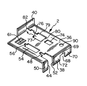
A cut-out 76 is provided in base member 36 and
extends to rear wall 40. Cut-out 76 includes a first
edge 80, side edges 77 and 7g, and rear edge 82. First
edge 80 is located behind slot 74 and parallel to front
downwardly extending front wall 38. Edge ~0 has a length
larger than the width of saw chain g so that either left
hand cutters 10 or right hand cutters 12 can be received
by cut-out 76~ Side edges 77 and 79 extend rearwardly
from front edge 80 to upwardly extending wall 40. Also,
side edges 77 and 79 are mirror images of each other and
have a plurality of sides so that cut-out 76 can receive
the cutter which is to be sharpened and a portion of saw
chain 9 located directly behind the cutter. Edge 82 is
located in upwardly extending wall 40 and is connected to
side edges 77 and 79.
In operation, as shown in Fig. 7, leg portions
70 and 72 straddle a portion of saw chain 9 behind cutter
12. The chain rests against upper edge 69 of notch 68.
Rectangular slot 74 receives triple raker assembly 33L.
Cut-out 76 receives cutter 10 exposing cutting edge 28L
above the top surface 66 of the base member 36 of guide
2. A portion of saw chain 9 behind the cutter is also
received by cut-out 76 so that wall 82 rests on saw chain
9. File guide 2 is angled by wall 82 and upper edge 69
to correspond to the top surface o~ the cutting edge 28L.
The cutting edge is then sharpened using a file.
Typically, a circular ~ile is used to sharpen
this type of cutting edge. The file must be the correct
- 8 -
,-
.
',
77515
diameter in order for the cutting edge to be properly
sharpened. For this reason, a hole 90 havinq a diameter
which corresponds to the proper circular file diameter
for sharpening the blade is provided in the base member
36 of the guide so that an operator may check to see that
he is using the proper size file.
It should be noted that each cutting edge and
corresponding depth gauge is filed independently of
adjacent cutting edges and depth gauges. Also, guides of
different sizes and configurations are required for saw
chains having cutting teeth with different pitches.
Having described the presently preferred
embodiment of the invention, it is to be understood that
it may otherwise be embodied within the scope of the
appended claims.
:
-
~.