Note: Descriptions are shown in the official language in which they were submitted.
DIspENsING AND MIXING APPARAT~S
FIELD OF TH~ INVENTION
This invention relates to dispensing devices and more
particularly to a combination of a dispensing device and a
disposable mixing device employing stationary mixing
elements for use therewith. Still more particularly, it
relates to the combination of a dispensing device and a
disposable mixer with means for both preserving the
integrity of and preventing contamination between two or
more fluids being dispensed, and for maximiziny the mixing
of the fluids with a minimum of pressure drop along the axis
of the mixing device.
BACKGRO~ND OF THE INVENTION
Dispensing devices of this general type, as is well
known in the art, are useful in the application of a variety
of pasty or highly viscous products such as adhesives, joint
filler agents, foams, sealants, molding compounds etc.,
whereas the products consist of two or more components to be
: stored separately, before use to be mixed however in order
to start a chemical reaction between them, usually causing a
solidification or hardening of the mass. ln using the
device, the content of the cartridge is pressed out of each
; (Keller-Chen)
",,: . ,~ ,
barrel by actuation of a delivery plunger, the components
flowing from the orifice into and through the attached mixer
unit where ~hey become closely intermixed. Usually the
content of a cartri~ge is dispensed intermittently in
several portions, whereas the components joined within the
mixer will steadily react during the idle intervals. If the
intervals are long enough. the mixer will become inoperable
and will have to be replaced. This is due to the fact that
the components will cure at the interface between the
cartridge and the mixer and, due ~o diffusion, this curing
will extend back in to the cartridge. This ~ay hinder the
detachment of the mixer (ordinarily left on the cartridge),
but even worse, solidified particles or ~clods" formed in
the mass will block the further dispensing of the cartridge
content and will cause defective application, such as
rippled surface on articles, faulty joints, etc.
is an object of the invention to eliminate these
drawbacks and to afford unimpeded delivery of the cartridge
content and faultless application thereof upon repeated
replacement of the mixer unit and after extended time
intervals between partial deliveries.
Dispensing and mixing combinations have been known in
which fluids to be mixed have been dispensed by double
barrelled syringe or caulking gun type dispensers (see e.g.
U.S. Patents nos. 3,30g,814~ 4,041,463, and 4,538,920).
These prior devices are included among those described above
and have several specific drawbacks. The '814 patent employs
(Keller-Chen) 2
a moving mixing element and it leaves the two fluids to be
mixed in close juxtaposition at the delivery point of the
syringe~ and hence subject to cross-contamination. In
addition, the mixer was not conveniently disposable, and
leaves the orifice of the dispenser subject to contamination
by admixture of the two fluids. The '463 patent discloses a
disposable mixing device for use with a two barrelled
dispenser and a baffle which extends into the mixer.
Contamination between the two fluids at the orifice of the
dispenser is avoided by a rubber seal. The '920 patent
discloses a disposable mixing tube secured to a double
barrelled syringe type dispenser in which a premix chamber
is used to split each of the separate streams prior to their
reaching the mixing elements. The disadvantages of this type
of premixing are that it introduces a substantial pressure
drop in the mixing line and does not cooperatively
contribute to the mixing action of the stationary mixing
elements further downstream.
The objects of this invention are to overcome some or
all of the disadvantages of the prior art. More
particularly, it is an object to provide a dispenser and
disposable mixer combination in which cross-contamination
between a plurality oi fluids is avoided at the orifice end
of a multibarrelled dispenser without substantial pressure
loss. Still another object is to accomplish the foregoing
objectives and at the same time direct the moving streams in
~Keller-Chen) 3
1~7~;4~
such a way as to enhance the mixing action of the stationary mixing
elements downstream.
In accordance with one aspect of the invention there is
provided in a device for the simultaneous delivery of a plurality
5 of separate fluids to a dispensing point downstream of which the
fluids are to be admixed, the combination comprising: a delivery
orifice for said device for delivering said fluids to said delivery
point; a baffle in said orifice for separating said fluids upstream
of said delivery point having a transverse radially extending
10 downstream end; a mixing tube having an inlet and an outlet end; a
plurality of each of first and second stationary mixing elements in
said tube; said mixing elements substantially in the form of
twisted ribbons spanning the interior diameter of said mixing tube
and having transverse radially extending entrance and exit ends;
15 said mixing elements further comprising means for directing the
flow of said fluids in helical paths around the axis of said tube,
said first elements directing it in one direction and said second
elements directing it in the opposite direction; means for fixing
said elements in said tube with the first and second elements
20 alternating along the axis of said tube and with the entrance of
r each downstream element set at approximately right angles to the
exit end of the next element upstream thereof; means at the inlet
end of said tube for releasably securing said tube to said orifice
circumferentially sealing said orifice; means for preventing cross
25 contamination of the fluids comprising ribbon-like separation means
affixed to said tube in the inlet end of said tube having a
transverse, radial].y extending inlet end in abutment with and
sealing the downstream end of said baffle when said tube is secured
~776~
. ~
- 4a -
to said orifice for maintaining the separation and integrity of
said fluids each to itself for a substantial distance within said
mixing tube downstream of the downstream end of said baffle; and
means in said tube for holding said separation means in abutment
with and at right angles to the antrance end of the next element
downstream.
BRIEF DESCRIPTION OF TH~ INVENTION
In the accomplishment of these and other objects of the
invention, in a preferred embodiment thereof, a two-component
dispensing device is employed comprising a twin-barreled dispensing
cartridge, with two dispensing channels separated by a partition
wall and each of the barrels leading into a common orifice in which
a baffle separates the two streams and terminates at its downstream
end with a transverse radially extending end, and further
comprising a static mixer unit releasably attached to said orifice,
said mixer unit having a plurality oE mixing vanes stacked in
succession with alternating right-hand and left-hand twist and
fixed in alternately offset rotary position within a mixing tube.
A feature of the invention is that a ribbon-like separating
element is used in the mixing tube with its upstream end in
abutment with the downstream end of the orifice baffle and its
downstream end in abutment and at right angles to the next mixing
element downstream.
A further feature is that the connection between the mixing
tube is arranged so that when it is fully connected to the
dispenser there is a substantial residual spring
.,
~7764~
compression between the separation element and the end o
the baffle~
Still another feature is that the separating means is
arranged to direct the fluids in a helical path, and the
mixing element next downstream is arranged at right angles
to the separation means and to reverse the direction of the
helical path to maximize the mixing ac~ion between the
separation element and the mixer.
Additional features are the simplicity and ease of
~nanllfacture .
DEs~RIplrIoN OF THE D~AWINGS
A preferred embodiment of the invention selected fox
purposed of illustration only, is shown in the accompanying
drawings in which:
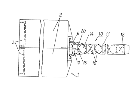
Fig. 1 is a side view of a two-component dispensing device.
consisting of a twin-barreled dispensing cartridge and a
static mixer unit, shown partly in section;
Fig. 2 is a view of the cartridge of Fig. 1 as seen from the
side of the orifice; and
Fig. 3 is an inlet end view of the mixer unit of Fig. 1.
(Keller-Chen) 5
7~641~
,~ ~
The illustrative embodiment of the invention herein
described comprises a dlspensing device 1 sho~n in Fig. 1
employing two cylindrical parallel barrels 2, each having a
delivery plunger or piston 3 for the delivery of the
cartridge contents. From the storage chamber in each barrel
2 a dispensing channel 5 communicates with a common orifice
6 of the catridge, the two channels being separated up to
and within the orifice by a baffle 4 the downstream end of
which is in the form of a line extending radially across the
orifice 6 which is surrounded by a base plate 7 for
detachably and fittingly moun~ing a static mixer unit 10
cornprising a mixing tube 11 to the orifice. Said base plate
7 is provided with two juxtapositioned claws 8 for mounting
the mixer unit 10 in the manner of a bayonet or quarter-turn
fastener. This makes it possible for the mixing tube 11 to
be releasably attached to and sealed around the orifice 6
which is provided with a flange 12 for this purpose. In
connecting the mixer unit to the cartridge, the flange is
put against the socket plate 7 between the claws 8 in a
~` rotary position 90o offset fronl that in Fig. 3, and then
rotated by a quarter turn whereby the flange grips under the
claws 8. By means of two stops 13 provided on the flange 12,
abutting against claws 8, the rotary position of the
connected mixer unit 10 is fixed in relation to the baffle.
Within the tube 11 of the static mixer unit 10 are
stacked longitudinally in succession, as known per se, a
plurality of stationary mixing vanes 14, 16 with alternating
(Keller-Chen) 6
. ..,~ .
right-hand and left~hand twi~t and fixed in the tu~e
alternately at right angles. In the present mixer design.
all of the ~1xing ele~ents 14,16 are preferably ormed in a
~i~gle molding 80 as to ~orm a ~ixing ele~ent a8sembly and
they are fixed as a ~ingle unlt in the tube 1. A subdivision
into two or more ~ectional elements is, however, pos~ible.
The first element 14 can be a ribbon-like separator
having a transverse, radially disposed end corresponding to
that of the downstream end of the baffle 4. Whatever its
form is, it is placed in the inlet end of the tube 11, with
its upstream end in tight abuttment with the end of the
baffle 4. This separator 14 may be contoured as one of the
mixing elements, or it can merely serve to maintain the
integrity and separation of ~he two streams ~ith varying
degrees of twist to flat.
It is necessary that the first element 14 (i.e. the
separation means) of the mixer unit be fixed relative to the
mixing tube 11 such that its inlet edge 15, after connecting
the mixer unit 10 to the twin cartridge 1, as described
befor~, is oriented parallel to and in abuttment with the
downstream end of baffle 4 in the orifice.
Accordingly the separation means 14 continues a
substantial distance into the mixing tube 11 beyond the
interface 20 (delivery point) between the end of the orifice
and the first point at which the two, usually reactive,
fluids actually contact each other. This distance is
selected to ensure that, even during lengthy idle periods
~Keller-Chen) 7
- ~ 277~
after dispensing has begun, no reaction or h~rdening of the
cartridge content can occur either at the delivery point 20
of the arifice or by diffusion back into the cartridge.
The neces~ary rela~ive po&ition of the ~eparator 14
(and, c~ons~quently, of the following vanes 16) within the
mixing tube 11 m~y be achieved preferably by means of a
tight fit, i~ e. by matching the diameters of the ~anes and
the bore of the tube. In the embodiment shown, however, the
separator 14 is somewhat extended at its inlet edge lS in
the direction of the tube diameter, the eXtensiOnfi resting
in corre~ponding notches 17 provided in the ~ube wall (Fig.
3). By this means, axial pressure is provided between the
inlet edge lS and the downstream end of baffle 4 to ensure
tight connection. The inlet end lS may preferably be formed
with a bevel. If all the elements 14, 16 are formed, as
usual, as as a single piece including both right and left
mixing elements ( of molded plastic~, it is possible to fix
the mixing elements as a united assembly in the tube 11 at
its exit end 18 axially and in rotary position with respect
to the tube 11 (e. g. as known per se, by means of cam-like
guide~ at the innerside of th~ tube) in order to ensure the
correct connection of the inlet edge lS; by suitably
dimensioning of the lengths of the mixing element assembly
and the tube, in that case, the inlet edge 15 may be urged
with residual spring compression against the end of baffle 4
by slightly compressing the mixing element assembly axially
when joining the mixer unit 10 with the cartridge 1.
(Keller-Chen) 8
~77g i4~
~ aving now described a prefered embodiment of the
invention, it will now be obvious to those skilled in the
art that modificAtions ~nd adaptation~ thereof ~an be ~ade
without depsrting from the ~plrit of the invention. Thus, it
i8 not necessary that it be limited to the di~pensing of two
fluids inasmuch as additional fluids can be delivered
simultaneou~ly. In this case, the separator ribbon element
14 needs only to keep the fluids separated. This can be
accomplished by forming it radially outwardly from the axis
of the tube, with as many vane portions 8S there are fluids.
Further modifications will be apparent to those ~killed in
the art and therefore it i5 not our intention to limit th.
invention ~o the precise form shown in the drawings by
rather to l~mit it only in the terms of the appended claims
... .. : :