Note: Descriptions are shown in the official language in which they were submitted.
~ C~778~7
GRANULATOR FOR CROSS-LINKA8LE PLASTIC
The present invention relates to a granulator device and
particularly, to a device for producing granules which are formed
out of a cross-linkable plastic compound.
More specifically, the present invention relates to a device
that is particularly suited for forming granules out of a cross-
linkable plastic compound which are intended for manufacturing
cross-linkable, extruded insulation, such as, for example, cable
insulation.
Cables with extruded, cross-linkable insulation are produced
by forming, by means of an extruder fed with cross-linkable
plastic granules, an insulation over the conductor.
Subsequently, the extruded insulation is cross-linked.
For realizing cross-linked insulations having high
dielectric strength, it is necessary for the insulation itself to
be perfectly uniform and to be without any discontinuity. This
requires that the granules, with which the extruder is fed, to
have uniform characteristics, and to not contain any small
agglomerations or lumps of cross-linked material which have
already become partially or totally cross-linked.
The known granulators for cross-linkable plastic compounds
do not differ from those used for linkable plastic compounds
which are not cross-linkable. Examples of granulators of this
type are those described in U.S. Patents Nos. 3,114,169 and
3,323,170. Such known granulators are unable to guarantee, in an
absolute manner, the absence of already partially cross-linked
agglomerations or lumps of the granules in the mass of granules
produced.
The known granulators comprise an extruder, in communication
with an extruder head, which is adapted to continuously draw a
plurality of filaments of a plastic compound. A rotating blade,
~.Z77817
connected to the extruder head, cuts these filaments as they are
gradually formed and in this way, provide the granules.
In particular, the extruder head of the known devices,
comprises a slab or die provided with a plurality of through-
holes which are parallel to one another and which are distributed
in an annular crown-shaped formation which is coaxial to the axis
of the slab itself. The compound, coming from the extruder,
enters the extruder head, and it is conveyed into the through-
holes by means of a funnel-shaped conduit which increases in
diameter in the direction of said slab.
In spite of every care taken when conveying the compound of
cross-linkable material toward the holes in the slab, the known
granulators have not succeeded in preventing static portions of
the compound inside the extruder head. The cross-linking which
is commenced at these portions gives rise to formations of lumps
and agglomerations of partially or completely cross-linked
material, at least in the granules.
Accordingly, the material of the granules produced is not
uniform which causes the formation of extruded cross-linked cable
insulation with a discontinuous and non-uniform structure and
hence, with a degradation of its dielectric strength. Therefore,
cables with such defects are subject to a great probability of
perforation or breakdown risks during operation.
One object of the present invention is to provide a compact
granulator for cross-linkable plastic compounds which does not
have the drawbacks found in the known granulators because the
granulator of the insulation is capable of producing granules
which are all substantially formed of an uncross-linked, cross-
linkable material and which all have uniform characteristics.
In accordance with the present invention, the granulator
comprises an extruder head which contains a filter and which is
provided with a slab having a plurality of through-holes which
1~:'77817
are parallel to one another and which are distributed in an
annular crown-shaped array coaxial to the slab. An annular,
funnel-shaped conduit, which increases in size in the direction
of the slab opens against one of the sides of the slab where the
through-holes are present, and a rotating blade is adjacent the
other side of the slab. The granulator has at least an annular
channel which communicates with the exterior of the granulator
and with the coupling zone between the funnel-shaped annular
conduit and the slab. Preferably, the annular channel comprises
a first annular channel at the radially outermost edge of the
funnel-shaped annular conduit at the slab, and a second annular
channel at the slab and at the radially innermost edge of the
funnel-shaped annular conduit, said first and second channels
communicating with the exterior of the granulator.
Other objects and advantages of the present invention will
be apparent from the following detailed description of the
presen~ly preferred embodiments thereof, which description should
be considered in conjunction with the accompanying drawings in
which:
Fig. 1 is a schematic cross-sectional side view of
the granulator of the invention;
Fig. 2 is a fragmentary, enlarged, cross-sectional view
of a portion of the slab having holes for the passage of the
compound being extruded;
Fig. 3 is a fragmentary, enlarged, end view of a
portion of a face of said slab; and
Fig. 4 is a fragmentary, enlarged, perspective view
of a portion of the cutting blade granulator in
association with said slab.
lZ778~7
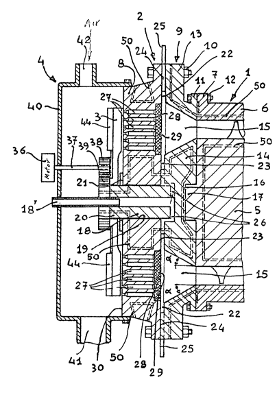
As can be seen in Fig. 1, the apparatus of the invention
comprises an extruder 1, an extruder head 2 provided with a
rotatable blade 3 and a collecting chamber 4 for the granules
produced.
The extruder 1 is a screw-type of extruder, and it includes
a screw 5 enclosed inside a casing 6 which is provided with a
flange 7 for connecting it to the extruder head 2.
The extruder head 2 comprises a die in the form of a slab 8
and a body 9 (both to be described in detail hereinafter) which
are secured together at their edges, for example, by means of
through-bolts 10.
The body 9 has a flange 11 which is secured to the flange 7
of the extruder casing 6 by through-bolts 12. Said body 9 is
formed by an annular element 13 and by a disc 14. The annular
element 13 which encircles and is coaxial to the disc 14, forms,
with the disc 14, a funnel-shaped, annular conduit 15 which
increases in size in the direction of the slab 8. In particular,
the walls of the conduit 15 have an angled~ of inclination with
respect to the axis of the slab 8, and this angle has a value in
the range from 0 to 35.
When the inclination of the walls of the conduit 15 is of an
angle ~ over 35, the plastic filaments formed at the radially
outermost zone of the extruder head have a lower rate of
formation than those formed in the radially innermost zone of the
extruder head.
Bearing in mind that the blade cuts all the filaments
substantially simultaneously to provide the granules, granules
having different lengths would be obtained. Therefore, granules
of non-uniform dimensions are obtained since the granules formed
in the radially innermost zone of the extruder head would have
1277817
greater lengths as compared to those which are formed in the
radially outermost zone of the extruder head.
The annular element 13 is interposed between the slab 8 and
the cylindrical casing 6 of the extruder and is also secured to
both. The disc 14 has, in a central position of the side facing
the extruder screw 5, a cavity 16 which receives a protuberance
17 extending from the head of the screw 5.
Also, at the other side of the disc 14, there is a tubular
member 18 which passes through a hole 19 made in the central
portion of the slab 8. The free end 20, of the tubular member 18,
extends from the slab 8, and the member 18 is secured to the slab
8 by means of a ring-nut 21.
As previously stated, the body 9 and the slab 8 of the
extruder head, are coupied together, and this coupling takes
place through the contact had between their reciprocally facing
surfaces. Such facing surfaces are such as to provide, in the
reciprocal coupling zone, at least one annular channel which
communicates with the exterior of the apparatus. Preferably, the
reciprocally facing surfaces of the body 9 and the slab 8 have
the characteristics described hereinafter.
The surface of the body 9 which faces the slab 8 has
circular channels22 and 23 at the larger end of the annular
conduit 15. The channel 22 is at the radially innermost edge of
the annular element 13 of the body 9, and the circular channel 23
is at the radially outermost edge of the disc 14.
Grooves 24, extending from the channel 22, are formed on the
surface of the annular element 13 which is in contact with the
slab 8. The grooves 24 extend to the outer edge of the annular
element 13 where they are connected to the tubes 25 by which
rejected plastic material may be conveyed elsewhere, such as to a
waste bin.
iZ77817
Channels 26 put the channel 23 of the disc 14 into
communication with the bore of the tubular member 18 which also
receives a tube 18' which traverses the collecting chamber 4, the
chamber 4 being described in further detail later herein. In
this way, in the coupling zone between the slab 8 and the body 9,
there are provided a first annular channel 22 which communicates
with the exterior of the extruder-head and which is at the
radially outermost edge of the funnel-shaped, annular conduit 15
and a second annular channel 23 which communicates with the
exterior and which is at the radially innermost edge of the
funnel-shaped annular conduit 15.
Although a particular embodiment of the first and the second
annular channels for putting the funnel-shaped annular conduit 15
into communication with the exterior has been described, it will
be apparent to those skilled in the art that such channels may be
otherwise provided.
What is of importance for the purpose of the invention, is
the presence of at least one annular channel which communicates
with the exterior, and preferably, of first and second annular
channels which communicate with the exterior and located,
respectively, at the radially innermost and radially outermost
edges of the funnel-shaped annular conduit 15, and disposed where
the conduit 15 meets the slab 8. As a consequence, any
configuration of the extruder head 2 which provides at least one
annular channel, and preferably, said first and second annular
channels, in communication with the exterior, will accomplish the
object of the invention.
The slab 8 has a plurality of through-holes 27 which are
parallel to one another. Said through-holes in the slab 8 are
disposed in such a way as to provide circular arrays thereof
which face the funnel-shaped, annular conduit 15. At the side of
the slab 8 which faces the body 9, the slab 8 has a circular
1277817
recess 28 which overlies the entire zone where the through-holes
27 are present.
Inside the recess 28, there is a filter 29 made, for
example, of a metallic netting having the form of an annulus with
its inner and outer radii being substantially the same as those
of the circular arrays of through-holes 27 in the slab 8.
The component parts of the extruder and of the extruder head
are temperature regulated, such as by means of circulating
pressurized water in the conduits 50 (shown in broken lines in
Fig. 1).
Figs. 2 and 3 illustrate, in enlarged scale, a portion of
the slab 8 which has the through-holes 27. As is seen in Fig. 2,
starting from the side ~0 of the slab 8 which is the side in
contact with the blade 3 (Fig. 1), the through-holes 27 have the
following configuration.
Each through-hole 27 has a cylindrical end portion 31, and a
cylindrical central portion 31' of greater diameter than the end
portion 31. These two cylindrical portions 31 and 31' are
connected to each other through a truncated cone portion 32.
The central portion 31' terminates at one end with a flared
portion 33 extending to the recess 28 at the other side of the
slab 8, i.e., the side against which the funnel-shaped annular
conduit 15 ends (Fig. 1).
As can be seen in Fig. 3, the flared portions 33 of adjacent
through-holes 27 are tangent to one another. Moreover, the
surfaces 34 between the flared portions 33 have a pyramid-form
with sharp corners 35 and curvilinear sides 36.
As previously described and is shown in Figs. 1 and 4, a
rotating blade 3 is connected to the extruder head 2. The
rotating blade 3 is rotated on an end portion 20 of the tubular
member 18 and is rotatable by a motor 36 through a shaft 37 and
the gears 38 and 39. The rotating blade 3 is enclosed inside a
~2778~7
casing 40 which provides a chamber 4 for collecting the granules
which are produced and which are removed from the chamber 4
pneumatically through the aperture 41 by means of an air stream
supplied through the aperture 42, the air stream also cooling the
granules.
Fig. 4 illustrates in enlarged scale detail one of said
blades 3 and a portion of the slab 8 of the device. As can be
seen in Fig. 4, the blade 3, which moves in the direction of the
arrow 43 and overlies the slab 8, carries a compressed air
reservoir 44. The reservoir 44 is connected, through a tube 45,
to a E~ se known compressed air device (not shown) which is
capable of providing such air to the reservoir 44 while said
reservoir moves with blade 3. Nozzles 46 extend from the
reservoir 44 and direct a flow of compressed air against the
blade surface 47 which is the upstream or trailing su~face with
respect to the direction of movement of the blade 3. In this
way, the edge 48 of the blade is kept clean thereby eliminating
the presence on it of residues of cross-linkable material.
The functioning of the granulator, according to the
invention, will now be described.
The extruder screw 5, which is rotated around its own axis
by a motor (not shown in the drawings), causes a cross-linkable
plastic compound to advance towards the funnel-shaped, annular
conduit 15 of the extruder head 2. The funnel-shaped, annular
conduit 15 directs the compound towards the plurality of through-
holes 27 in the slab 8.
That part of the compound which, during its passage into and
through the funnel-shaped, annular conduit 15, contacts the walls
of the conduit 15, does not pass into the through-holes 27, but
flows, instead, outside of the extruder head 2 and hence, of the
apparatus, by passing through the first and the second annular
channels 22 and 23 at the joining zone between the slab 8 and the
lZ778~7
body 9, of the extruder head. The part of the compound which
reaches the through-holes 27 issues forth from the holes 27 in
the form of cross-linkable plastic filaments.
The rotating blade 3 cuts the cross-linkable plastic
material filaments as they gradually form, thereby providing
granules which are collected in chamber 4. The granules are
removed from the chamber 4 pneumatically, by means of an air
flow.
Apart from providing for the pneumatic transportation of the
granules, the air flow also causes the granules to cool which
prevents conglomeration of the granules.
From the description of a specific embodiment of a
granulator of the invention and from the considerations set forth
hereinafter, it will be understood how the objects of the
invention are attained.
In a granulator according to the invention, the presence of
annular channels which communicate with the exterior of the
granulator and which surround the portion of the slab 8 having
the through-holes 27, prevents the formation of static portions
of cross-linkable plastic compound inside the extruder head 2.
Considering the fact that such static portions of cross-
linkable plastic materials in the compound are undesirable, since
at least the beginnings of cross-linking of the compound itself
takes place therein, the elimination of such static portions
means that the granulator of the invention produces
substantially only granules which are not cross-linked.
Therefore, the granules will have uniform characteristics in the
component material.
Hence, for avoiding any formation of said static portions,
the presence of at least one annular channel 22, and preferably,
of two annular channels 22 and 23, is essential.
1~,'77817
Other elements of the device also contribute to assuring the
complete achievement of these results.
One of these other elements is constituted by the compressed
air nozzles 46 which keep the blades 3 clean by preventing any
particles of cross-linkable material compound from forming and
remaining on the blades.
Another element is the particular configuration of the
surface of the slab 8 which faces the funnel-shaped, annular
channel at the portion thereof where the through-holes 27 are
present, as was previously described with reference to Fig 3.
In fact, the presence of the flared portions 33 of the
through-holes 27 and the fact that the surface of the slab 8
between such flared portions and adjacent through-holes 27 has
the shape of a pyramid provided with sharp corners and
curvilinear sides, eliminates the possibility of static portions
of the plastic material occurring when the compound passes
through the extruder head.
Thus, risks of alterations of the compound taking place,
through an incipient vulcanization of the compound, are
eliminated and hence, maximum uniformity of the material of the
produced granules is assured.
Finally, the presence of the filter 29 in a recess in the
slab 8 and in contact with the portion of the slab 8 where the
through-holes 27 are present permits the granulator of the
invention to have maximum compactness.
Although preferred embodiments of the present invention have
been described and illustrated, it will be apparent to those
skilled in the art that various modifications may be made without
departing from the principles of the invention.