Note: Descriptions are shown in the official language in which they were submitted.
Description
Load Responsive Control System Adapted to Use of
Neqative Load Pressure in O~eration of~ Controls
Technical Field
This invention relates generally to a load
responsi~e control system and more particularly to a
control system that selectively derives energy from a
negative type load for the operation of the system
controllers.
Back round of the Invention
In prior art the control components, like
for example direction and flow control valves, used in
control of fluid motors subjected to loads, respond to
manual, electrical or other remote control signals, at
a comparatively low energy level, by proportionally
amplifying such signals for transmittal to the control
elements of the system, though the use of fluid power
energy. Such fluid power energy can be derived from a
separate source of fluid power, or from the main
syskem pump, which powers the hydraulic system.
The use of a separate source of fluid power
to provide the energy for operation of the system
controls is very desirable, since it is completely
independent of the duty cycle of the primary hydraulic
power system. However, such an independent source of
pressure suPfers from several disadvantages, like for
example inefficient use of power, especially with the
hydraulic system in standby condition. Also in mobile
type systems, using internal combustion engines as the
prime mover, such a separate source of fluid power
needs a separate power takeoff, which is not only
~ ;, .
--2
expensive, but also utilizes a lot of space, which in
such applications is at a premium.
Many industrial and mobile type systems use
fluid flow at system pressure derived from the main
system pump. In such systems, especially during the
control of negative loads, the system pressure, which
is dictated by the magnitude of the load, may drop to
a pressure level below that required by the system
controls~ This disadvantage can be overcome by
preventing the discharge pressure of the system pump
dropping below a certain minimum pressure level, as
dictated by the characteristics of the system
controls. Some of those controls, especially of an
electro-hydraulic servo type, well known in the art,
require a relatively high pressure level, which
results in the loss of large amounts of fluid power in
the main fluid power system, especially when
controlling small positive loads, or negative type
loads~
Another disadvantage of this approach
results from the trend, well known to those skilled in
the art, of using in mobile systems maximum operating
~ system pressures, well in excess of say 5000 PSI. In
: such systems not only pressure reducing type devices
must be interposed between the main system pump and
system controls, but the use of say 5000 PSI pressure,
at substantially high flow levels, to supply fluid
power to system controls, at say 1000 PSI pressure
level, results in large amounts of fluid power being
converted to heat by throttling, loss in system
efficiency and loss of power derived from the system
pump to perform the work at the tool.
3~
- ~ ~L27~
Summarv of the Invention
In one aspect of the present invention a
load responsive control system is provided comprising
at least one actuator operable to control a positive
and a negative load, exhaust means and a source of
pressure fluid, first valve means operable to
selectively interconnect said actuator with said
exhaust means and said source of pressure fluid and to
control fluid flow to and from said actuator, control
means operable to control fluid flow to and from said
actuator, and second energizing means operable to use
energy from said negative load while said actuator
controls a negative load. The control means also has
first energizing means operable to use energy from
said source of pressure fluid while said actuator
controls a positive load.
It is therefore a principal object of this
invention to use the energy of the negative load being
controlled by the hydraulic system to either fully
supply the energy required by the system controls, or
at least to supplement and therefore decrease the
amount of energy extracted from the main power
circuit, during control of such negative loads.
It is another object of this invention to
use the flow at negative load pressure, to supply the
fluid power demand of the system controls, during
control of negative load, in such a way that the flow
extracted at negative load pressure does not affect in
any way whatsoever the accuracy and response of the
controls used in positioning, or in control of the
velocity o~ the negative load.
It is still another object of this
invention, in a system simultaneously controlling
multiple positive loads and at least one negative
load, to use the flow at negative load pressure to
supply fluid power demand of the system controls, for
control of ~oth positive and nagative loads.
It is still another object of this invention
to increase the level of the negative load pressure by
the energy derived from the system pump to a certain
minimum predetermined negative load pressure level,
required for operation of the system controls.
Briefly the foregoing and other objects of
this invention axe accomplished by using the energy of
the negative load, which is supported by the negative
load pressure developed in the fluid motor, and which
must be converted into heat by throttling, during
control of such a load, to per~orm useful work not
only in providing ~luid power to the system controls
u~ed in control of fluid motors subjected to negative
and positive loads, but also for the use of other
system controls and to perform other useful work.
Additional objects of this invention will
become apparent when referring to the preferred
embodiments o~ this invention as shown in the
accompanying drawings and described in the following
detailed description.
Description of the Drawinas
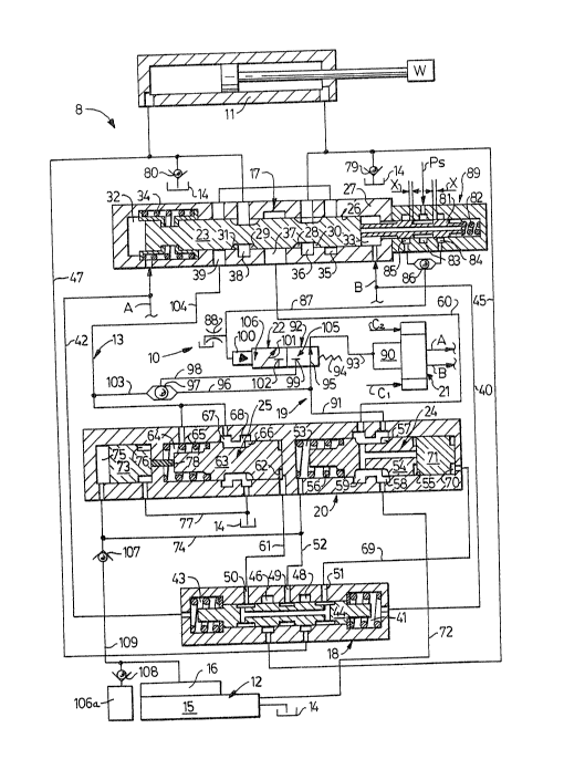
Fig. 1 shows a sectional view of a direction
control valve together with a sectional view of the
system throttling controls, including positive and
negative load compensators, a sectional view of an
external logic module and system actuakor, with system
pump, system reservoir and spool positioning controls
shown diagrammakically, all connected into a working
circuit by schematically shown fluid conducting lines;
and
Fig. 2 shows a sectional view of a direction
and flow cvntrol valve, throttling controls including
-5-
positive and negative load compensators and an
external logic module, with fluid motor, system pump,
system reservoir, fluid power diverting valve~ spool
positioning controls, other fluid motors and
corresponding control valves, and negative load
pressuxe shuttle logic system shown diagrammatically,
all connected into a working circuit by schematically
shown fluid conducting lines.
Descri~tion of the Preferred Embodiments
Referring now to the drawings and for the
present to Fig. 1, a load responsive control system 8
is provided and includes a load responsive valve
assembly, generally designated as 10, interposed
between an actuator 11 operably connected to a load W
and a fluid conducting system including a source of
pressure fluid, generally designated as 12, and
exhaust means 13 which includes a reservoir 14. The
source of pressure fluid 12 includes a pump 15,
~o provided with an output fl~w control 16, which may be
of a bypass type, or of a variable displacement type,
well known in the art, and which may respond, in a
well knswn manner, to the maximum load signal pressure
of the load responsive fluid power and control system
of Fi~. 1.
The load responsive valve assembly 10
comprises first valve means, generally designated as
17, shown in Fig. 1 in khe form of a spool type
direction and flow control valve, well known in the
art, load pressure identifying means, generally
designated as 18, and control means, generally
designated as 19, which may include load pressure
compensating means, generally designated as 20, flow
control means, generally designated as 21, and
interconnecting means, generally desiqnated as 22.
First valve means 17 is provided with spool means,
such as a direction control spool 23, while load
pressure compensating means 20 is provided with
positive load compensating means~ generally designated
as 24, and negative load compensating means, generally
designated as 25, which are of a single stage type.
The functional relationship between load pressure
compensating means 20, which are used in control of
both positive and negative loads and first valve means
17, including the direction control spool 23, are
similar to those described in detail in my U.S~ patent
4,222~409, issued September 16, 1980. Briefly, fixst
valve means 17 comprises the direction control spool
23, slidably guided in a bore 26 in a housing 27. The
direction control spool 23 is provided with inflow
variable metering ori~ice means, such as positive load
or inflow metering slot~ 28 and 29 and outflow
variable metering orifice means, such as negative load
or outflow metering slots 30 and 31. One end of the
~o direction control spool 23 projects into control space
32, subjected to pressure or control signal A, while
the other end projects into control space 33,
subjected to pressure of control signal B. In a well
kn~wn manner the direction control spool 23 may be
maintained in neutral position, as shown in Fig. 1, by
centering spring 34, well known in the art. Bore 26
intersects first exhaust chamber 35, first load
chamber 36, a supply chamber 37, second load chamber
38 and second exhaust chamber 39. One end of the
direction control spool 23, protruding into control
space 32 and subjected to the pressure of control
signal A is subjected to a force equal to the product
of the pressure of control signal A and
cro s-sectional area of the direction control spool
23. The other end of the direction control spool 23,
~Z7~
--7--
protruding into control space 33 and subjected to
pressure of the control signal B, is subjected to a
force equal to the product of the pressure of control
signal B and cross-sectional area of direction control
spool 23. Control space 33, of first valve means 17,
is connected by line 40 to a first control chamber 41
of the load pressure identifying means 18. In a
similar manner control space 32 is connected by line
42 to a second control chamber 43. First load chamber
36 is connected by line 45 with a chamber 26, while
second load chamber 38 is connected by line. 47 with
chamber 48. First and second con-trol chambers 41 and
43 and chambers 46 and 48 are included in load
pressure means 18, which is provided with load
pressure identifying logic shuttle. 44. Load pressure
identifying means 18 can be of any type operable to
identify load pressure signals, for example a check
valve logic, shuttle valve logic, or electrical logic,
which are all capable o~ identifying load pressure
signals as positive or negative. Both the
construction and operation of the load pressure
identi~ying means 18, as shown in Fig. l, were
described in great detail in my U.S. patent 4,610,194,
issued September 9, 1986. Briefly, depending on
whether the load W is positive or negative, in respect
to the intended correction in its position, full
displacement of the logic shuttle 44 in either
direction, either connects positive load pressure to a
port 49, or connects negative load pressure to ports
50 and 51.
The positive load pressure port 49 is
connected by line 52 to space 53 of positive load
compensating means 24, which is provided with a
throt-tling spool 54. The throttling spool 54 is
subjected to positive load pressure in space 53,
~æ~ t
--8--
pressure in space 55 and to the biasing force of a
spring 56. The throttling spool 54 by the throttling
action of throttling ports 57 controls the fluid flow
from an inlet chamber 58 to an outlet chamber 29,
which is connected by line 60 with the supply chamber
37 of the first valve means 17. When controlling a
positive load, in a manner well known to those skilled
in the art, the throttling spool 54, will
automatically establish a modulating position,
throttling by throttli.ng port ~7 the fluid flow from
the inlet chamber 58 to the outlet chamber 59, to
maintain a relatively constant pressure differential
across an orifice created by displacement of the
positive load metering slots 28 or 29.
The port 50 subjected to negative load
pressure is connected by a line 61 to a control
chamber 62 of a negative load compensating means 25,
which is provided with a throttling spool 63. The
throttling spool 63 is subjected to the negative load
pressure in the control chamber 62, pressure in space
64 and to the biasing force of a spring 65. The
throttling spool 63 by the throttling action of
throttling port 66, controls the fluid flow from an
outlet chamber 67 to an exhaust chamber 68, which is
connected to the reservoir 14. When controlling a
negative load, in a manner well known to those skilled
in the artl the throttling spool 63 will automatically
establish a modulating position, throttling by
throttling port 66 the fluid flow from the outlet
chamber 67 to the exhaust chamber 68, to maintain a
relatively constant pressure differential across an
orifice created by displacement of the negative load
or outflow metering slots 30 or 31.
The port 51, subjected to negative load
pressure, may be connected, as shown in Fig. 1, by
- 9 -
line y9 to space 70 in communication with a free
floating piston 71. During control of positive load
with negative load pressure in space 70 at a very low
level the free floating piston 71 is automatically
maintained in the position as shown in Fig. 1, not
affecting in any way whatsoever the control action of
the throttling spool 54. During control of negative
load, once the negative load pressure, acting on the
cross-sectional area of the free floating piston 71,
rises to a certain predetermined level, at which it
will balance the preload of the spring 56, the free
floating piston 71, together with the throttling spool
54 will move from right to left to a position in which
the inlet chamber 58, connscted by a line 72 to the
pump 15, becomes isolated ~rom the outlet chamber 59,
which is connected by line 60 with the supply chamber
37. Therefore, during control of negative load, above
a certain minimum negative load pressure level, as
d~termined by the preload in the spring 56, with the
use of the ~ree floating piston 71 the condition of
so-called negative load regeneration is achieved,
which provides a synchronizing action between positive
load compensating means 24 and negative load
compensating means 25.
In the absence of the synchronizing feature
of negative load regeneration, a free floating piston
73 can be used, which may be subjected to positive
load pressure transmitted through line 74 to space 75
and to pressure in space 76, connected by line 77 to
the reservoir 14. Therefore the free floating piston
73 is subjected to a force e~ual to the product of the
positive load pressure in space 75 and its
cross-sectional area. This force is transmitted
through a free floating pin 78 to the throttling spool
63 and during control of positive load forcibly
.. ..
~34~
--10--
maintains the throttling spool 63 in fully open
position, as shown in Fig~ 1. During control of
negative load, the positive load pressure signal in
spaces 75 and 53 will be equivalent to the pressure at
the inlet of the actuator 11. Under those conditions,
through the action of the free floating piston 73, the
throttling spool 63 is subjected to the force feedback
related to the inlet pressure of the actuator 11,
providing a synchronizing effect between the
compensating action of the positive load compensating
means 24 and negative load compensating means 25 and
preventing development of excessive pressures in the
actuator 11 through ~nergy derived from the pump 15
during control o~ negative load.
With use of both free floating pistons 71
and 73, as shown in the embodiment of Fig. 1, during
control of negative load the condition of negative
load regeneration is achieved, automatically providing
synchronization between positive load compensating
means 24 and negative load compensating means 25 with
the pu~p 15 isolated from the actuator 11 and inlet
flow to the actuator 11 provided through the makeup
valves 79 and 80 from the reservoir 14. During
control of positive load the free floating piston 71
remains in position as shown in Fig. 1, while the free
floating piston 73, subjected to positive load
pressure transfers a force through the free floating
pin 78, which maintains the throttling spool 63 in
fully open position as shown.
The end of the direction control spool 23,
which protrudes into control space 33, is maintained
in contact with a shuttle 81, subjected to the biasing
force of a spring 82. The shuttle 81 therefore moves
with the displacement of the spool 23 and, in a manner
well known to those skilled in the art, sequentially
- ~2~
connects a chamber 83, subjected to Ps pressure, with
the chamber 84 or 85, while also s~quentially
connecting those chambers to the pressure of the
control signal B, existing in rontrol spare 33.
Therefore, with the displacement of the direction
control spool 23 and the shuttle 81 through a distance
X in either direction, either chamber 84 or 85 will be
connected to Ps pressure. Therefore with the
displacement of the shuttle 81 through distance X in
either direction, through the action of a shuttle 86,
well known in the art, Ps pressure will be transmitted
through line 87 to interconnecting means 22. With the
shuttle 81 in neutral position, as shown in Fig. 1,
through the action of a leakage orifice 88, the line
87 will be subjected to atmospheric pressure. The
action of the shuttle 81, combined with the action of
the shuttle 8~, constitutes a signal generator and
provides means responsive to position of spool 23,
generally designated as 89.
Flow control means 21, in response to the
command signals Cl and C2, generates A and B pressure
signals, which are respectively transmitted to spaces
32 and 33 and, in a manner as described above,
generate forces, which establish the displacement of
the direction control spool 23, which in turn, due to
the compensating action of the load pressure
compensating means 20, establish, in a well known
manner, the proportional fluid flow to and from ths
actuator 11. As is well known to those skilled in the
art, the flow control means 21, for generation of A
and B control pressure signals, can take many forms,
the specific form being determined usually by whether
the control signal Cl or C2 is electrical or hydraulic
and by the degree of amplification of those command
signals energywise to produce and A and B control
pressure signals. In any event, the energy to amplify
Cl and C2 command signals is usually supplied from a
source of pressure which can be either an independent
pump, or the system pump 15. Especially if the system
pump 15 is used as a source of pressure, a~ shown n
Fig. 1, it is customary to introduce a pressure
reducing control 90 in order to prevent subjecting the
flow control means 21 to excessive pressures.
The inlet chamber 58, connected by line 72
to the pump 15 in the embodiment of Fig. 1, is
connected through line 91, a connectinq means, such as
a 3-way valve, generally designated as 92, and line 93
to the pressure reducing control 90. Under those
conditions the flow control means ~1 is provided with
*luid power energy derived from the pump 15 and
therefore the fluid power generated hy the pump 15 is
used in amplification of C1 and C2 signals to produce
A and B pressure signals~
The 3-way valve 92, schematically ~hown in
Fig. 1, is of a form well known in the art and is
biased towards position as shown by a spring 94. In
this position the segment of 3-way valve 92 by passage
95, connects lines 91 and 93, which in turn are
connected by line 96 to a shuttle valve means, such as
a shuttle 97, while the output of the shuttle 97
transmitted through line g8, is blocked by a StGp 99.
With the pressure in the line 87 exceeding a level as
determined by the preload in the spring 94, in a well
known manner, the 3-way valve 92, through the action
of an actuating means, such as an actuator 100, will
be shifted into a position in which passage 101 will
connect the line 98 with the line 93, while the line
91 is effectively blocked by an isolating maans, such
as a stop 102. The shuttle 97 is connected by a line
-~3-
103 and a line 104 with the first and ~econd exhaust
chambers 35 and 39.
Positive load pressure signals from the
valve assembly 10 and another schematically shown
system 106a are connected through the check valve
logic system of check valves 107 and 108, well known
in the art, in such a way ~hat only the maximum
positive load pressure of the loads heing controlled
is transmitted through line lO9 to the output flow
control 16 of the pump 15.
First energizing means, generally designated
as 105, is operable to interconnect the pump 15 with
flow control means 21 and includes the 3-way valve 92
provided with passage 95 connecting lines 91 and 92.
Second energizing means, genPrally
designated as 106, is operable to interconnect the
first and second exhaust chambers 35 and 39, sub~ected
to negative load pressure, to flow control means 21,
permitting the use of negative load pressure for
amplification of Cl or C2 command signals into A and B
control pressure signals and includes 3-way valve 92
provided with passage 101~ which connects, in response
to the pressure in line 87, the line 98 with line 93.
Interconnecting means 22 includes 3-way
valve 92, the shuttle 97, fluid conducting lines
connecting the shuttle 97 with the source of negative
load pressure and means 89 responsive to the position
of the valve spool 23.
Referring now to Fig. 2, like components of
30 Figs. 1 and 2 are designated by ].ike numerals. All of
the basic aomponents of valve assembly 10 of ~ig. 2,
namely first valve means 17, load pressure
compensating means 20, flow control means 21 and load
pressure identifying means 18 are identical to those
3 5 of Fig. 1, although first valve means 17 of Fig. 2 is
-14-
not provided with means 89 responsive to position of
spool 23. Tha main differences between the embodiment
of Figs. 1 and 2 are that in Fig. 2 the other system
106a is shown composed of multiple loads W connected
to multiple actuators lla~ llb and llc, controlled
respectively by schematically shown flow control means
2la, 2lb and 21c, which in turn are operably connected
to first valve means 17a, 17b and 17c, which in turn
may be functionally interconnected to individual load
pressure compensating means 20. The outlet chambers
of first valve means 17a, 17b and 17c are connected by
lines 104a, 104b and 104c with a negative load
pressure shuttle logic system, generally designated as
110, which includes shuttle valves 111, 112 and 113,
which, in a manner well known to those skilled in the
art, will transmit the maximum negative load pressure
signal of the negative loads being controlled to ~ine
114, connected to the actuator 100 and the stop 99 of
the 3-way valve 92.
Interconnecting means 22 of Fig. 2 includes
3-way valve 92, the negative load pressure shuttle
logic 110, fluid conducting line 114 and line 91
connected to the system pump 15. Interconnecting
means 22 supplies either positive or negative load
pressure to the presRure reducing control 90, which
supplies fluid power energy at Pc pressure to the flow
control means 2la, 2lb and 21c.
Referring now back to Fig. 1, the presence
of pressure in line 87 develops a force in the
actuator 100 of the 3-way valve 92, which is opposed
by the biasing force of the spring 94. Once the force
developed in the actuator 100 becomes greater than the
biasing force of the spring 94, in a well known
manner, the 3-way valve 92 is moved into a position,
in which the system pump 15 becomes isolated from the
-15-
pressure reducing control 90 by the stop 102 and the
outlet of the actuator 11, subjected to the negative
load, is simultaneously connected by passage 101 to
the pressure reducing control 90 of flow control means
21. In this way the fluid power for control signal
amplification is supplied to the flow control means 21
from the stored energy in the negative load. Any
diversion of fluid power at negative load pressure
during control of negative load would normally result
in a change of position of such a negative load and
therefore would adversely affect the stability,
proportionality and transient response of the negative
load control. However, in the embodiment of Fig. 1,
the velocity of the negative load, due to the
compensating action of negative load compensator means
25, is directly proportional to the flow area of the
negative load, or outflow metering slots 30 or 31,
caused by the displacement of the direction control
spool 23. Since the fluid power at negative load
pressure is supplied from downstream of the outflow
metering slots 30 or 31, and from upstream of negative
load compensating means 25, any diversion of fluid
flow at negative load pressure will be automatically
compensated through the amount of flow being throttled
by the throttlin~ port 66 of negative load
compensating means 25. In this way the negative load
energy can be diverted from the negative load control
circuit, within the total amount of available energy,
to perform other work, without affecting in any way
whatsoaver the quality of control of the negative
load. In this way, since during control of negative
load, the energy used by the negative load control is
directly derived from the negative load and not from
the system pump, not only the negative load energy,
which during the negative load control must be
16-
converted into h~at by throttling in the negative load
controls, is used for a useful purpose, thus
increasing the system efficiency, but also by not
utilizing the fluid power from the pump circuit for
negative load controls, the capability of the system
pump to perform useful work is increased.
Once negative load compensating means 25 is
used in control of a load, the presence of pressure in
exhaust means 13, which includes first and second
exhaust chambers 35 and 38, and which is positioned
upstream of the throttling port 66, automatically
signifies that the controlled loa~ is of a negative
type and that the system controls use the outflow ~rom
the actuator 11, in control of such a negative load.
The shuttle 97 interconnects exhaust means 13 and the
system pump 15 and, in a well known manner, only the
higher pressure input of the two will be transmitted
to line 98. There~ore if the pump pressure is higher
than the negative load pressure, the line 98 will be
subjected to pump pressure. If the negative load
pressure is higher than the pump pressure, through the
action of the shuttle 97, the line 98 will be
subjected to negative lsad pressure. If the minimum
pump pressure is so selected that it will meet the
requirement of the flow control means 21, ensuring
that no negative load pressure can be transmitted
below this preselected level, the line 98 can be
directly connected to the pressure reducing control
90, completely eliminating the need for the 3-way
valve 92, or means 89 responsive to position of the
spool 23. Under those conditions, through the use of
the simple shuttle 97, the energy of the negative load
can be used to supply fluid power to flow control
means 21.
- ~2~ 4
-17-
Under certain conditions, for maximum system
efficiency, it is an advantage to completely unload
the system pump 15, through the action of the output
flow control 16, if the negative load pressure is high
enough to supply the requirements of flow control
means 21. The spring biased 3-way valve 92 ensures
that the energy of the negative load can only be
diverted to flow control means 21 above a certain
minimum negative load pressure level. With this
approach the output line 98 from the shuttle 97 can be
connected to and supply the control signal to the
actuator 100. In this way the preload of the spring
94 will dictate the pressure level, at which the fluid
power from the negative load is connected to flow
control means 21. With such an arrangement this
negative load pressure level, in certain specific load
responsive systems, can be made to unload the system
pump 15, through its output flow control 16.
In the embodiment of Fig. 1, the presence of
control pressure in line 87 leading to the 3-way valve
92 determines whether or not to divert the negative
load energy to the flow control means 21. This is
determined by the action of means 89, responsive to
the position of spool 23. Within the range of
displacement of the direction control spool 23 equal
to X, irrespective of the magnitude of the negative
load the energy to operate flow control means 21 is
directly derived from the system pump, through the
passage 95. Once the direction control spool 23 is
displaced through a distance greater than X, in either
direction, the Ps pressure signal is transmitted from
means 89, through the shuttle 86 to the actuator 100.
Ps pressure can be supplied in response to any
specific parameter of the system, or can be the actual
pressure of the negative load and therefore can be
-18-
directly supplied from the port 50 or 51 of load
pressure identifying means 18. If the Ps pressure is
the negative load pressure then, in a manner as
described above, the 3-way valve 92 wili only connect
the energy from the negative load to the flow control
means 21, above a certain minimum negative load
pressure level, as determined by the preload of the
spring 94. The displacement of the direction control
spool 23, within the distance X, signifies that the
energy requirement o~ the flow control means 21 is
small and therefore it might be preferable to use for
control purposes the energy derived from the system
pump. For large displacement of the direction control
spool 23 large flows are required to displace it,
requiring a higher use of energy. Under those
conditions it is an advantage to use the energy of the
negative load and conserve the energy from the pumpO
The embodiment of Fig. 1 shows the
synchronization of positive load compensating means 24
and negative load compensating means 25 using both
negative load regeneration, through the action o* the
free floating piston 71 and through variation in the
control pressure differential of the negative load
compensating means 25, by the action of the free
floating piston 73. The use of those two
synchronizing methods results in the functional
system, as described above. It should be noted
however that the principal of variable pressure
differential, using the free floating piston 73 to
synchronize positive and negative load compensation,
would normally be used in the control systems
characterized by high frequency xesponse, while the
use of ne.gative load regeneration, through the action
of free floating piston 71, would be used in systems
49~
--19--
where system efficiency is of greater importance than
the accuracy of the control.
Referring now back to Fig. 2, the control
systems of Figs. 1 and 2 are very similar and result
in very similar control characteristîcsO The
embodiment of Fig. 2 is of great advantage in a system
in which a multiplicity of positive and negative loads
are simultaneously controlled. The shuttle valve
logic o~ Fig. 2 automatically supplies the energy from
the negative load, at the negative load pressure to
flow control means 21, ensuring that the source of
negative load energy can only be connected to flow
control means 21, above a certain predetermined
negative load pressure level, as dictated by the
characteristics of the flow control means 21. Since
this energy, derived ~rom the negative load, can be
used simultaneously for operation of flow control
means 21, 2la, 2lb and 21c, irrespective of whether
they control po~itive or negative load, great savings
in energy can be achieved greatly increasing system
efficiency, while also preserving the energy of the
pump for control of positive loads.
The direction control spools 23 of Figs. 1
and 2 are shown spring centered towards their neutral
position by springs 34. As is well known to those
skilled in the art, the direction control spools 23,
in a well known manner, can be connected to spool
position transducers, liXe for example LVDTs and the
feedback signal from such transducers, together with
the command signals C1 and C2, can be used in
positioning of the direction control spools 23, usiny
differential type amplifiers well known in the art.
The embodiments of Figs. 1 and 2 show the
use of fluid power, generated by a negative load on a
selective basis, to provide the energy for use in flow
~378q~
-20-
control means 21. It should be noted that this
selective use of the energy of the negative load, to
supplement the energy derived from the system pump,
especially in the embodiment of Fig. 2, can be used
for other purposes than amplification of the control
signals and can be used to operate other system
components. Therefore, the fluid flow at Pc pressure
can be used not only in amplification of the control
signals, but to provide the energy to perform useful
work in other components of the system. In this way
the energy of negative loads, during control of such
loads, can be used on a selective basis to supplement
the energy derived from the system pump, not only
increasing system efficiency, but also increasing the
capacity of the system pump to perform useful work.
Although the preferred embodiments of this
invention have been shown and described in detail it
is recognizPd that the invention is not limited to the
precise form and structure shown and various
modifications and rearrangements as will occur to
those skilled in the art upon full comprehension of
this invention may be resorted to without departing
from the scope of the invention as defined in the
claims.