Language selection

Search

Patent 1279229 Summary

Third-party information liability

Some of the information on this Web page has been provided by external sources. The Government of Canada is not responsible for the accuracy, reliability or currency of the information supplied by external sources. Users wishing to rely upon this information should consult directly with the source of the information. Content provided by external sources is not subject to official languages, privacy and accessibility requirements.

Claims and Abstract availability

Any discrepancies in the text and image of the Claims and Abstract are due to differing posting times. Text of the Claims and Abstract are posted:

  • At the time the application is open to public inspection;
  • At the time of issue of the patent (grant).
(12) Patent: (11) CA 1279229
(21) Application Number: 526087
(54) English Title: REINFORCED PLASTIC RETAINER RINGS FOR SHEET METAL FORMING
(54) French Title: BAGUE DE RETENUE EN MATIERE PLASTIQUE ARMEE POUR LA MISE EN FORME DES TOLES
Status: Deemed expired
Bibliographic Data
(52) Canadian Patent Classification (CPC):
  • 113/57
(51) International Patent Classification (IPC):
  • B21D 11/02 (2006.01)
  • B21D 37/10 (2006.01)
  • B29C 33/12 (2006.01)
  • B29C 39/10 (2006.01)
(72) Inventors :
  • MARTELL, WILLIAM A. (United States of America)
(73) Owners :
  • GENERAL MOTORS CORPORATION (United States of America)
(71) Applicants :
(74) Agent: GOWLING WLG (CANADA) LLP
(74) Associate agent:
(45) Issued: 1991-01-22
(22) Filed Date: 1986-12-22
Availability of licence: N/A
(25) Language of filing: English

Patent Cooperation Treaty (PCT): No

(30) Application Priority Data:
Application No. Country/Territory Date
864,317 United States of America 1986-05-19

Abstracts

English Abstract


REINFORCED PLASTIC RETAINER RINGS
FOR SHEET METAL FORMING

Abstract of the Disclosure
A reinforced plastic retainer ring for use in
a sheet metal stretch forming process. The ring is
reinforced with a plurality of metal brackets embedded
in the rim portion generally radially aligned toward
the center of the ring.


Claims

Note: Claims are shown in the official language in which they were submitted.


The embodiments of the invention in which an
exclusive property or privilege is claimed are defined
as follows:

1. A plastic retainer ring, used to secure a
workpiece in a sheet metal stretch forming process,
said ring having a body portion with an opening therein
for receiving a forming die, said body being formed of
a polymeric material and including a rim portion
defining said opening, said rim portion being subject
to large substantially radially inward stresses during
said stretch forming process, said rim comprising a
plurality of spaced apart, generally radially aligned
reinforcing members having a projected finger portion
extended into and embedded within said rim portion and
an elongated portion extended from said finger portion
into said body portion of the retainer ring, a working
surface containing a beaded, curved section for
securing said sheet metal workpiece, whereby said large
substantially radially inward stresses acting on said
rim portion during said stretch forming process are
alleviated by the stress distribution from said rim
portion to said body portion through the reinforcing
members.


2. A plastic retainer ring, used to secure a
workpiece in a sheet metal stretch forming process,
said ring having a body portion with an opening therein
for receiving a forming die, said body being formed of
a polymeric material and including a rim portion
defining said opening, said rim portion being subject
to substantially radially inward stresses during said


stretch forming process, said rim comprising a
plurality of spaced apart, generally radially aligned
reinforcing members having a projected finger portion
extended into and embedded within said rim portion and
an elongated portion extended from said finger portion
into said body portion of the retainer ring having
locking means for preventing relative movement between
said reinforcing member and said retainer ring, a
working surface containing a beaded, curved section for
securing said sheet metal workpiece, whereby said
substantially radially inward stresses acting on said
rim portion during said stretch forming operation are
alleviated by the stress distribution from said rim
portion to said body portion through the reinforcing
members.


3. A plastic retainer ring, used to secure a
workpiece in a sheet metal stretch forming process,
said ring having a body portion with an opening therein
for receiving a forming die, said body being formed of
a polymeric material and including a rim portion
defining said opening, said rim portion being subject
to substantially radially inward stresses during said
stretch forming process, said rim comprising a
plurality of spaced apart, generally radially aligned
reinforcing members having a projected finger portion
extended into and embedded within said rim portion and
an elongated portion extended from said finger portion
into said body portion of the retainer ring having
locking means including apertures, tabs and corrugated
sections for preventing relative movement between said
reinforcing member and said retainer ring, a working


surface containing a beaded, curved section for
securing said sheet metal workpiece, whereby said
substantially radially inward stresses acting on said
rim portion during said stretch forming operation are
alleviated by the stress distribution from said rim
portion to said body portion through the reinforcing
members.

4. A plastic retainer ring, used to secure a
workpiece in a sheet metal stretch forming process,
said ring having a body portion with an opening therein
for receiving a forming die, said body being formed of
a polymeric material and including a rim portion
defining said opening, said rim portion being subject
to substantially radially inward stresses during said
stretch forming process, said rim comprising a
plurality of spaced apart, generally radially aligned
reinforcing members having a projected finger portion
extended into and embedded within said rim portion and
an elongated portion extended from said finger portion
into said body portion of the retainer ring, a working
surface containing a beaded, curved section for
securing said sheet metal workpiece, said reinforcing
members having locking means including apertures, tabs
and corrugated sections for preventing relative
movement between said reinforcing member and said
retainer ring, and a wire member linking said
reinforcing members through said apertures whereby
said substantially radially inward stresses acting on
said rim portion during said stretch forming operation
are alleviated by the stress distribution from said


11

rim portion to said body portion through the reinforcing
members.

5. A method of casting a reinforced plastic
retainer ring for use in securing a workpiece in sheet
metal stretch forming process including the steps of
providing a pattern of a die having an exterior surface
defining the interior surface of said retainer ring;
orienting said pattern in a pattern box the interior
surface of which defines the exterior surfaces of said
retainer ring; applying a release coating to the surfaces
of the pattern and the box; assembling and placing a
plurality of spaced apart, generally radially aligned
reinforcing members into said pattern box along the
periphery of said pattern, said reinforcing members
having projected fingerportions equipped with apertures
which are positioned adjacent to the pattern; connecting
said reinforcing members through said apertures with a
flexible wire member; pouring a polymeric casting
compound into said pattern box and demolding said
retainer ring after fully cured.

11

Description

Note: Descriptions are shown in the official language in which they were submitted.


~2792Z9


D-9229 C-3826
REINFORCED PLASTIC RETAINER RINGS
FOR SHEET METAL FORMING

Field of_the Invention
The present invention generally relates to a
reinforced plastic retainer ring for use in a sheet
metal stretch forming process and, more particularly,
is concerned with a plastic retainer ring reinforced
with a plurality of reinforcing brackets for use in a
sheet metal stretch forming process.
Background of the Invention
In a sheet metal stretch forming process, a
set of forming tools normally consists of four major
pieces. They are a die, a punch, an upper retainer
ring, and a lower retainer ring. The retainer rings
are also known as binder rings. The upper and lower
retainer rings are used in holding a sheet metal
workpiece in place such that a die and a punch could
work jointly to deform the workpiece into a desired
shape. In a usual setup, the upper and lower retainer
rings and the punch are movable while the die is
stationary.
Traditionally, the retainer rings are machined
of high strength tool steel. While the strength and
durability of tool steel are adequate for sheet metal
forming use, extensive machining is required to obtain
the desired shape. As a consequence, it is very
expensive to make a retainer ring with tool steel
material. This machining cost becomes even more
prohibitive when prototype low volume tools are made.
In a prototype tool, many changes from the original
design are made before a final design is reached. In

12792~9


the case of low volume tools such as that used in a
limited production of a concept car, the tools must
also be made inexpensively.
To save time and expenses involved in
machining retainer rings in tool steel, attempts have
been made to make retainer rings by casting a polymeric
material. High strength polymeric materials such as
thermoset epoxies have been used for this purpose. The
major benefit realized in using cast epoxy retainer
rings is that they may be cast to size saving the
expenses of machining. However, while epoxy materials
have good mechanical properties, we found that epoxies
used alone without other reinforcement produced
retainer rings that are easily failed after a few
forming cycles. We have observed that most of the
failures occurred at the rim portion, i.e., material
immediately adjacent to the brim of the opening of the
retainer ring. This is because in a sheet metal
stretch forming process, the rim portion of the
retainer ring which grips the edges of the metal sheet
preventing it from slipping into the die cavity is
subjected to very large radially inward stresses. As a
consequence, chunks of epoxy material at the rim
portion frequently broke away from the body portion of
the retainer ring.
It is therefore an object of the present
invention to provide a mechanically reinforced plastic
retainer ring that can be used in a sheet metal stretch
forming process without failure.


1279229


It is another object of the present invention
to provide a metal bracket reinforced plastic retainer
ring to be used in a sheet metal stretch forming
process which can be made at low cost.
Summary of the Invention
In accordance with a preferred practice of my
invention, a reinforced plastic retainer ring can be
made which is durable for thousands of cycles. My
novel invention comprises a plurality of spaced apart
reinforcing members each having a projected finger
portion extended into and embedded within the rim
portion of the retainer ring and an elongated portion
extended from the finger portion into the body portion
of the retainer ring. This plurality of spaced apart
reinforcing members enable the distribution of the
large substantially radially inward stresses acting on
the rim portion to the body portion of the retainer
ring during a sheet metal stretch forming process.
This stress distribution alleviates the large stress
concentration in the rim portion which would otherwise
occur and cause failure without such reinforcing
members. A reinforced plastic retainer ring made in
accordance with my novel invention can be used in a
sheet metal stretch forming process up to several
thousands of cycles without failure.
Other objects, features and advantages of the
present invention will become apparent upon
consideration of the drawings and specification that
follows:


~Z79Z;~9


Brief Description of the Drawings
FIG 1 is a perspective view of a tooling
arrangement used in sheet metal stretch forming
processes showin~ a punch, an upper retainer ring and a
lower retainer ring.
FIG 2 is a perspective view of a pattern box
containing a pattern and a plurality of reinforcing
members connected by a flexible wire prior to the
casting of epoxy.
FIG 3 is a perspective view of a finished
lower retainer ring containing the reinforcing members.
FIG 4 is a sectional view 4-4 taken from FIG 3
showing the reinforcing members embedded in the
retainer rings.
FIG 5 is an isometric view of a reinforcing
member having tabs, apertures, and corrugated sections.
Detailed DescriDtion of the Preferred Embodiment
Referring initially to FIG 1, a tooling setup
for a sheet metal stretch forming process is shown. An
upper retaining ring 10 is mounted on hydraulic
cylinders 12 for vertical movement. Anchors 14 are
located at the four corners for alignment purpose into
seats 22 in lower retainer ring 20. Punch 30 is
partially shown in FIG 1 located inside the upper
retainer ring 10. Upper retainer ring 10 has a working
surface 16 which mates with working surface 24 on the
lower retainer ring 20. It should be noted that a die
member is not shown in FIG 1 which is normally located
inside the opening of the lower retainer ring 20.
FIG 2 shows pattern 30 having the shape and
contour of a die positioned in pattern box 40 prior to
casting. The walls 42 of pattern box 40 define the

lZ7~2~9


exterior surfaces of the lower retainer ring 20 after
casting. A plurality of reinforcing members 50 which
are typically stamped cold rolled steel are placed on
base 44 of pattern box 40 and radially aligned toward
the center of pattern 30. The reinforcing brackets 50
are placed at a distance of approximately between 1 and
2 inches apart with the finger portion adjacent to the
pattern. In my preferred embodiment, the brackets are
connected through an aperture at the finger portion of
the bracket by a flexible wire. After the reinforcing
brackets are positioned in place, other reinforcing
means such assteel rods, steel mesh, and particulate
reinforcement such as rocks are also placed in the box
before an epoxy casting compound is poured into the
box. A detailed description of a method to reinforce a
plastic die with steel rods, steel meshes, and
particulate fillers is given in U.S. Patent 4,601,867,
issued July 22, 1986 assigned to the assignee of this
invention. Any suitable high strength epoxy casting
composition may be used in the casting of retainer
rings. A release coating is normally applied to the
surface of the pattern and the box so that the retainer
ring may be easily separated from the pattern and the
box after casting. While my reinforcing brackets 50
function mainly as reinforcement for the rim portion of
the retainer ring, other reinforcements such as steel
rods, steel meshes, and particulate fillers are used
for two reasons. First, they reinforce the body
portion of the retainer ring for structural strength.

~Z792~9


Secondly, the addition of these reinforcements enable
minimal shrinkage of the epoxy casting compound such
that a cast-to-size epoxy retainer ring may be made.
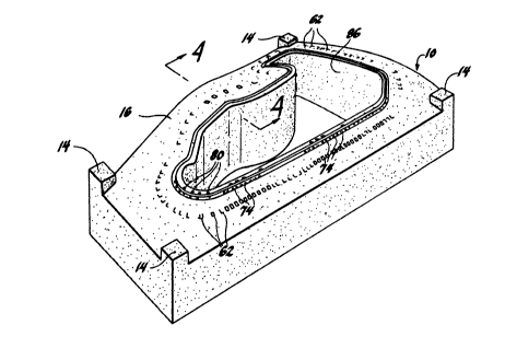
A completed upper retainer ring 10 is shown in
FIG 3. Section 4-4 in FIG 3 is shown in FIG 4. Note
that area 90 enclosed by the dashed line which is the
area immediately adjacent to brim 92 is defined as the
rim portion of the retainer ring. An isometric view of
the reinforcing bracket is shown in FIG 5. Note that
in FIG 5, reinforcing bracket 60 contains two tab
sections 62, two corrugated sections 64, and five
apertures 66 and 68. These are locking means for
preventing relative movement between the reinforcing
brackets and the epoxy medium of the retainer ring
after casting. The reinforcing bracket 60 further
contains a projected finger section 70 and an extended
body section 72.
Referring now to FIG 3, profiles of the
embedded reinforcing brackets are shown at the tabs 62
and the projected fingers 74. A beaded, curved section
80 (FIG 3 and FIG 4) which surrounds the opening of
retainer ring 10 works in cooperation with the beaded,
curved section 84 (FIG 4) in the mating retainer ring
20 for the gripping of a metal sheet workpiece. Punch
30 (FIG 1) slides against the inner surface 86 (FIG 3)
during a stretch forming process.
In my preferred embodiment, a flexible metal
wire is used to loosely link the reinforcing brackets
through aperture 66 (FIG 5) in a shish kebab
configuration for easier maneuverability. After the
retainer ring is cast, the metal wire is fixed to each
reinforcing bracket by the epoxy and acts as means for

1279Z29


stress transmission such that the stresses acting on
one reinforcing bracket may be distributed to its
adjacent brackets. Furthermore, the radially inward
stresses exerted on the rim portion of the retainer
S ring by the sheet metal workpiece is distributed to the
body portion of retainer ring by stress transfer from
the finger portion 70 to the body portion 72. This
stress distribution and transfer alleviate the stress
concentrations which would otherwise occur at the rim
portion of the retainer ring without such reinforcing
brackets. As a consequence, the possibility of
breakage or failure of the retainer ring at its rim
portions is eliminated.
While my invention has been described in terms
of one preferred embodiment thereof, other forms could
be readily adapted by one skilled in the art to achieve
the same results.


Representative Drawing
A single figure which represents the drawing illustrating the invention.
Administrative Status

For a clearer understanding of the status of the application/patent presented on this page, the site Disclaimer , as well as the definitions for Patent , Administrative Status , Maintenance Fee  and Payment History  should be consulted.

Administrative Status

Title Date
Forecasted Issue Date 1991-01-22
(22) Filed 1986-12-22
(45) Issued 1991-01-22
Deemed Expired 2002-01-22

Abandonment History

There is no abandonment history.

Payment History

Fee Type Anniversary Year Due Date Amount Paid Paid Date
Application Fee $0.00 1986-12-22
Registration of a document - section 124 $0.00 1987-03-10
Maintenance Fee - Patent - Old Act 2 1993-01-22 $100.00 1993-01-08
Maintenance Fee - Patent - Old Act 3 1994-01-24 $100.00 1994-01-07
Maintenance Fee - Patent - Old Act 4 1995-01-23 $100.00 1995-01-06
Maintenance Fee - Patent - Old Act 5 1996-01-22 $150.00 1996-01-08
Maintenance Fee - Patent - Old Act 6 1997-01-22 $150.00 1997-01-08
Maintenance Fee - Patent - Old Act 7 1998-01-22 $150.00 1998-01-08
Maintenance Fee - Patent - Old Act 8 1999-01-22 $150.00 1999-01-08
Maintenance Fee - Patent - Old Act 9 2000-01-24 $150.00 2000-01-07
Owners on Record

Note: Records showing the ownership history in alphabetical order.

Current Owners on Record
GENERAL MOTORS CORPORATION
Past Owners on Record
MARTELL, WILLIAM A.
Past Owners that do not appear in the "Owners on Record" listing will appear in other documentation within the application.
Documents

To view selected files, please enter reCAPTCHA code :


To view images, click a link in the Document Description column. To download the documents, select one or more checkboxes in the first column and then click the "Download Selected in PDF format (Zip Archive)" or the "Download Selected as Single PDF" button.

List of published and non-published patent-specific documents on the CPD .

If you have any difficulty accessing content, you can call the Client Service Centre at 1-866-997-1936 or send them an e-mail at CIPO Client Service Centre.


Document
Description 
Date
(yyyy-mm-dd) 
Number of pages   Size of Image (KB) 
Representative Drawing 2000-07-19 1 16
Drawings 1993-10-18 2 76
Claims 1993-10-18 4 134
Abstract 1993-10-18 1 9
Cover Page 1993-10-18 1 12
Description 1993-10-18 7 223
Fees 2000-01-07 1 28
Fees 1998-01-08 1 37
Fees 1999-01-08 1 21
Fees 1997-01-08 1 23
Fees 1996-01-08 1 29
Fees 1995-01-06 1 39
Fees 1994-01-07 1 32
Fees 1993-01-08 1 30