Note: Descriptions are shown in the official language in which they were submitted.
1279299
Pack for cigarettes or the like
Description:
~O
The invention relates to a cuboid pack for cigar-
ettes or the like, with an inner wrapping, especially made
of tin foil, which receives the pack contents, and with an
outer wrapping made of paper, cardboard or the like,
especial~y a soft-cuP pack, the inner ~rapping surrounding
the pack content to constitute a longitudinal overlap
extending in the longitudinal direction, and forming an
(upper) end wa~l composed of end tabs partially covering
one another.
The most common types of cigarette pack are con-
` structed so that the pack contents, in particular a
.
- cigarette group, surrounded by an inner wrapping are
accommodated in the actual pack. This pack can be a hinge- ¦
lid pack made of thin cardboard or a soft cup pack made
of paper. An outer wrapping consisting of cellulose or
polyethylene film is intended to ensure additional sealing
r of the pack contents against aroma and moisture losses.
however, since none of these wrappings guarantee leak-
proofing because of their construction, the aroma preser-
vation of these conventional cigarette packs is unsatis-
factory.
The object on which the invention is based is to
develop further and imProve a pack of the type mentioned
in the introduction, so that, whilst the conventional design
of the pack is largely maintained, a higher degree of pre-
servation of the pack contents against aroma and moisture
losses is guaranteed.
~o achieve this object, the pack according to the
''..':~. I
~ ' - '
' , ': .
~79299
-- 2
invention is char3cteri~ed in that the longitudinal over-
~ap of the inner wrapping is made leak-proof by means o~
adhesive bonding or welding.
The invention is preferably used with the "soft-cup"
type of pack. The cigarette group is surrounded by a
conventional inner wrapping, especially made of tin foil.
This is folded so that at least one longitudinal overlap
extending in the longitudinal direction of the cigarettes
is obtained and there are folds at least in the region of
one end wall. Preferably, the inner wrapping (tin foil
blank) is folded in such a way that the longitudinal over-
lap extends in the region of a front wa(l and, in addition
to the end wall, a bottom wall is also formed from bottom
tabs.
According to the teaching of the ;nvention, selected
regions of the overlaps and folds of the inner wrapping
are sealed off by means of adhesive bonding or welding.
In the simplest version, a considerable increase in leak-
proofing is achieved merely by means of a (continuous)
adhesive bonding of the longitudinal over(ap.
~; Further developments of the invention relate to a
modified design or folding of bottom tabs to form the
bottom wall, in such a way that an outer bottom - covering
tab, which essentially covers the surface of the bottom
wall, is bonded or welded to the remaining bottom tabs
along bonding strips located at the edges. As a result,
increased leak-proofing in comparison with conventional
designs of the inner wrapping is obtained (even) in the
region of the bottom wall.
3û According to a further proposal of the invention,
the end wall is also reshaped in terms of the design of
the end tabs, in such a way that a part region of the end
wall is sealed off by bonding strips of an outer end
covering tab. Only a region serving for opening the inner
wrapping, conventionally located next to a revenue or
closing stamp extending transversely over the end wall, is
designed in a customary way, that is to say with trapezoidal
longitudinal end tabs which are not bonded to one another
and which therefore allow the inner wrapping to be torn
.
1~7~3~9~3
-- 3
ODer or opened in this region in he usual way
Further features of the invention reiate to the
design of the end w2ll and bottom wall and to blanks for
inner wrappings of this type.
S Exemplary embodiments of the invention are
explained in detail below with reference to the drawings.
In the drawings:
Figure 1 shows a perspective view of a (sGft-cup)
pack for cigarettes,
Figure 2 shows the uPper end-wall region of the
pack according to Figure 1 during the opening of the iatter,
Figure 3 shows a front view of a cigarette group
with an inner wrapping (tin foil block),
Figure 4 shows a side view of the tin foil block
according to Figure 3,
Figure 5 shows a bottom view of the tin foil block
according to Figures 3 and 4,
Figure 6 shows a plan view of the tin foil block
according to Figures 3 and 4,
Figure 7 shows a (tin foil) blank for an inner
wrapping according to Figures 3, 4 and 5,
Figure 8 shows a (tin foil) blank for an inner
wrapping according to Figures 2 to 6.
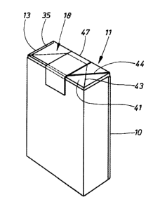
In the drawings, a cigarette pack is shown as a
preferred exemplary embodiment or practical example,
specifically, according to Figures 1 and 2, a soft-cup
pack. This consists of a soft cup 10 made of paper or the
like which is open at the top. The soft cup 10 is formed,
especially folded, in the customary way. A cigarette block,
in particular a tin foil block 11, is accommodated in this
actual pack. The dimensions are selected so that the tin
foil block 11 projects slightly from the soft cup 10. The
tin foil block 11 is formed from a cigarette group 12 as
the pack contents and an inner wrapping surrounding them,
in particular a tin foil blank 13. The latter consists in
the usual way of a preferably inner paper layer and an
aluminium layer.
The tin foil block 11 is cuboid, with a front wall
14, a rear wall 15, side walls 16 and 17, and an upper end
1~79Z99
-- 4
wal ~ 18 and a lower b;,ttom wal~ 19.
The inner wrapping, that is to say the tin foil
blank 13, surrounds the cigarette group 12, in such a way
that a longitudinal overlap 20 extending over the entire
length of the tin foil blank 13 is obtained in the region
of the front wal l 14 or rear wall 15, in the present case
in .the region of the front walL 14. The end wall 18 and
bottom wall 19 are formed by end tabs and bottom tabs which
likewise partially cover one another and which are yet to
be described in detail.
In the present tin foil block 11, the longitudinal
overlap 20 is hermetically sealed, specifically by means
of a bonding strip 23 connecting to one another edge strips
21 and 22 of the tin foil blank 13 which are provided in
the region of the overlap. This bonding strip 23 consists
of a suitable material, for example a glue strip provided
directly during the Production of the inner wrapping, or
an activatable hot-melt adhesive strip already previously
- coated on a sheet of material for producing the t;n foil
2û blanks 13. After folding has been carried out, the hot-
melt glue is activated by means of pressure and heat,
thus resulting in the sealed bonding of the edge strips
21 and 22. The longitudinal overlap 20 formed in this way
also extends into the region of the end wall 18 and bottom
wall 19.
During the production of the inner wrapping with
a hermetically sealed longitudinal overlap 20, the edge
strips 21 and 22 are connected to one another while they
are in a tubular intermediate folding position. The end
wall 18 and bottom wall 19 can then be formed in the
usual way by folding in end tabs and bottom tabs, without
these being connected to one another.
A further increase in the leak-proofing of the inner
wrapping can be achieved if (additionally) the bottom wall 19
is made (relatively) leak-proof. For this purpose, a spe-
cial fold is provided here. As can be seen particularly in
figures 7 and 8, a bottom covering tab 24 adjoining the area
of the rear wall 15 is divided off from the adjacent cuts
regions of the bottom tabs by means of lateral severing
.,-
- ' .
1279299
25 and 26 It is thereby possible to fold in such a
way that bottom side tabs 27 and 28 are first fo(ded onto
the pack content and then a longitudinal bottom tab 29 is
folded onto the pack content or onto the bottom side tabs
S 27, 28. The longitudinal bottom tab 29 assumes a trapez-
oidal shape, sPecifically because triangular folding
gussets 30 and 31 are folded in or between the bottom side
tabs 27 and 28, on the one hand, and the longitudinal
bottom tab 29 on the other hand
As an outer covering, the rectangular bottom
covering tab 24 is folded onto the above-described bottom
tabs and covers virtually the entire surface of the bottom
wall 19. As a result of an appropriate arrangement and
size of the lateral severing cuts 25 and 26, the bottom
covering tab 24 has a smaller length and smaller width
than the surface of the bottom wall 19. Corner seals 32
- and 33 are thus obtained at the corners facing the rear
wall 15.
The bottom covering tab 24 is connected in a leak-
proof manner to the remaining bottom tabs by means ofadhesive bonding or welding. In the exemplary embodiment
illustrated, there is attached to the inner face (paper
layer) a U-shaped bonding strip 34 which extends along the
free edges of the bottom covering tab 24 and which ensures
a substantially leak-proof closure of the bottom wall 19
as a result of adhesive bonding or welding to the longi-
tudinal bottom tab 29 and the bottom side tabs 27 and 28.
In this exemplary embodiment (Figure 7), the end
wall 18 can be folded in tbe conventional way in the form
of two trapezoidal longitudinal tabs partially covering
one another.
Alternatively, according to a further development,
the end wall 18 can also be designed with increased leak-
proofing. For this purpose an end c vering tab 35 like-
wise adjoining the rear wall 15lis divided off on ones;de from adjacent end tabs by means of a lateral severing
cut 36. Consequently, this region is of rectangular shape
and results in a covering of a part region of the end wall
18. The opposite region of the end covering tab 35 remains
1;~79299
connected .o an adja ent end side tab 37. When this end
side tab 37 and the second opposite end side tab 38 are
folded in, triangular folding gussets 39 and 40 are
obtained as a connection to an inner trapezoidal longi-
tudinal end tab 41 ~ecause of the lack of a severing cut,the outer end covering tab 35 is connected to the asso-
ciated end side tab 37 via a triangular folding gusset 42
likewise folded inwards, so that, on this side, both the
longitudinal end tab 41 and the end covering tab 35 form
ob(ique folding edges 43 and 44. These are intended to
make it possible to open the inner wrapping (tin foil
blank 13) when the cigarette pack is used, the folding
edge 44 being grasped in the usual way and a portion of the
end tabs being detached from the tin foil blank 13 in this
region.
The region of the end covering tab 35 outside the
folding edge 44 is connected to the end-tab regions
located underneath it by means of adhesive bonding or
welding. For this purpose, an L-shaped bonding strip 45
` 20 is arranged along the free edge of the rectangular part
of the end covering tab 35, with a transversely directed
leg 46. Substantial sealing of the end wall 18 is
thereby achieved even in this region, without the handling
of the cigarette pack or its external appearance being
impaired or altered. The size of the leg 46 of the
bonding strip is such that the end covering tab 35 is
connected in this region to the longitudinal end tab 41
located underneath.
A conventional closing strip or revenue stamp 47
is laid transversely over the end wall 18 of the tin foil
block 11 in the usual way and extends into the region of
the front wall and rear wall of the soft cup 1û. This
revenue stamP 47 covers the middle region of the end tabs
or end wall, but, even in the exemplary embodiment of
` 35 Figures 6 and 8, leaves free the non-bonded part of the
; end covering tab 35 and of the longitudinal end tab 41
(with the oblique folding edges 43 and 44). As a result,
this version of the inner wrapping or pack can also be
opened in the customary way, that is to say by grasping the
... . .
127~299
up~er oblique folding edge 44 of the end ruvering tab 35
and tearing off the latter along a side edge of the revenue
stamp 47 (Figure 2).
As can be seen, for examp(e, in Figures 7 and 8,
all the bonding strips can be attached to the spread-out
blank by being pressed on, especially where hot-melt strips
are concerned. Expediently, as regards tin foil blanks,
the bonding strips are only attached on the side of the
paDer layer.
'-'..','' ," '' - ' ''` ,' ~ ~ ' ,'
-
' - , ' ,