Note: Descriptions are shown in the official language in which they were submitted.
FIELD OF THE INVENTION
This invention relates to a hook useful in connecting
two cables or portions of the same cable.
DESCRIPTION OF PRIOR ART
_
In coastal waters, it is a common practice in the logging
industry to dump truck loads of logs into waterways for transport-
ation by towing to processing plants. Preferably, it is desired
to keep the logs in bundles for ease of handling and to minimize
loss during towing. A common method of retaining the logs in
bundles is to place two 5/8 inch wire rope cables around each
bundle of logs, the ends of the cables being joined together by a
fastener or hook (sometimes also called a bell, or a clamp, or a
thimble). A suitable type of hook is disclosed in Canadian patent
No. 629,905 to Binstead et al. However, a difficulty with a device
such as the Eoregoing, is that the wire rope cable as a result of
use, tends to become kinked or its ends may become frayed, thereby
making its insertion or removal Erom the device of -the foregoing
patent impossible withou-t cutting the cable. Not only is such
wasteful of wire rope cable, but in addition necessitates the pro-
visions of a suitable pair of cutters at any site where the logs
are being bundled or unbundled.
The above described problem is present not only in hooks
of the type described in Canadian patent No. 629,905, but also in
hooks which are used to interconnect orthogonal wires of a log
bundle. If a cable must be aut in such a situation, it particu- :
larly results in loss of a substantial amount of cable, since the
relatively shor-t cut pieces (for example perhaps about 20 feet in
length), are not sufficiently long to tie a bundle of logs.
, . -- 1 --
: . . . , .:
, : ,' ' ~ ' ' ..
.
:~ ;
'' : ''
63
SUMMARY OF THE INV~NTION
The present invention provides a cable thimble for
securing a cable means comprising a frame having a cable receiving
hole extending longi-tudinally therethrough, the hole being tapered
and of greater size at one end than at the other, a cable insert-
ing slot extending longitudinally of the frame at one side thereof
in communication with the hole throughout its length; a wedge
lengthwise insertable into the hole from its greater sized end,
the wedge being substantially correspondingly tapered with the
hole and being dimensioned such that a first cable means can be
passed through the slot into the hole by relative movement of the
thimble and the first cable means laterally and be frictionally
retained in the hole between cable re-taining surfaces on the
wedge and hole; and means formed in said frame to receive second
cable means.
The means to receive a second cable means conveniently
may be a second cable receiving hole which has a center spaced
apart from the Eirst hole, the second hole transversely intersect-
ing the first hole through the cable retaining surface thereof.
According to another feature of the invention, the
second hole may be substantially parallel to and spaced apart
from the first hole and conveniently may be provided with a
shoulder to permit abutment of a collar attached to a free cable
end of the second cable means. In one preferred embodiment the
first and second cable means is the same cable.
According to a preferred embodiment a cable thimble
; for securing a cable means comprises a frame having a first cable
'' "' , , . . ' ,', ' '
79~63
receiving hole extending longitudinally therethrough, the hole
being tapered and of greater size at one end than at the other, a
first cable inserting slot extending longitudinally of the frame
at one side thereof ln communication with the first hole through-
ou-t its length; a wedge lengthwise insertable into the hole from
its greater sized end, the wedge being substantially correspond-
ingly tapered with the hole and being dimensioned such that a
first cable can be passed through the slot into the first hole by
relative movement of the thimble and the first cable laterally and
be frictionally retained in the first hole between cable retaining
surfaces on the wedge and first hole; a second cable receiving
hole, the second hole having a center spaced apart from the first
hole and extending at an angle thereto to transversely intersect
the first hole through the cable retaining surface thereoE; and
a second cable inserting slot extending longitudinally of the
second cable receiving hole transversely of the frame and being
dimensioned such that a second cable can be passed through the
second slot into the second hole by relative movement of the
thimble and the second cable laterally of the second cable and be
frictionally retained in the second hole by pressure exerted by
the first cable through the intersection of the first and second
holes.
DRAWINGS
Embodiments of the invention will now be described
by way of example with reference to the drawings, in which:
FIGURE la is a perspective view of the embodiment of
the invention in a bundling hook or thimble, where a loop of
-- 3
` `~
. - '
.~ ." "' ' ' '. '' ' ~ '
: .- :. ' '
~L~7~3~6~
cable embraces a bundle of logs;
FIGURE lb is a perspective view of the embodiment of
the invention in a guppy hook or thimble;
FIGURE 2 is a perspective view of a thimble;
EIGURE 3 is a side elevation of the thimble of FIGURE 2;
FIGURE 4 is a cross-section along the line 4-4 of
FIGURE 3;
FIGURE 5 is a perspective view of another thimble of the
present invention;
FIGURE 6 is a side ellevation view of the thimble in
FIGURE 5;
FIGURE 7 is a cross-section along the line 7-7 of
FIGURE 6; and
FIGURE 8 is a perspective view of a wedge as used in the
thimble of FIGURES 2 through 4 and FIGURES 5 through 7.
DET~ILED DESCRIPTION OF THE EMBODIMENTS OF THE INVENTION
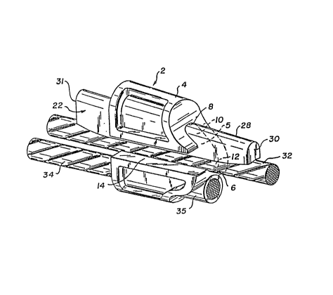
Referring first to FIGURES la, 2 to 4, a hook,
or thimble, 2, of a structure which may be referred to as a
bundling hook or thimble, is shown, which has a frame 4. First
and second parallel and adjacent holes, 5 and 16 respectively,
pass through frame 4. First hole 5 has a transverse shape shown
most clearly in FIGURE 4, and has a cable retaining surface 6 as
weIl as a surface 8 opposed to cable retaining surface 6. Within
an upper half 10 of first hole 5 is provided a wedge 22 slidably
mounted therein by means of a pin 20 extending from the frame 4
and slidably engaging in guideway 24 in wedge 22. A first slot
14 is also provided in the frame 4, the first slot 14 bèing of
a width such that a cable 32 can be passed transversely there-
..~
~J - 4 -
`' ' , '
:'.'.. .. ' ` . ~ :.,
.. . . . . .
9463
through, and into a lower section 12 of the first hole 5 with
its surface abutting the cable retaining surface 6 of first
hole 5. The wedge 22 has a forward end 30 as well as a wedging
surface 28 disposed lengthwise at an angle opposite a cable
retaining surface 26 of the wedge 22~ Both the cable re-
- -, ; , ' ' :
- . .
': ;
~79~6~
taining surface 6 of the first hole 6 and the cable retaining
surface 26 of wedge 22 are concave with a radius of curvature
equal to that of the cable 32 which is to be retained there-
between. In a typical application, cable 32 is about 5/8 inch
diameter. The cable retai.ning surface 26 of wedge 22 though is
provided with ridges 29 which extend laterally and lengthwise
thereon, so as to assist in retaining the cable 32 in a manner
which will later be described. The ridges 29 on cable retaining
surface 26 of wedge 22 are most clearly seen in FIGURE 8.
The wedge 22 and the first hole 5 are dimensioned such
that when the cable 32 is positioned between the cable retaining
surface 26 of wedge 22 and the cable retaining surface 6 of first
hole 5, the wedge 22 can be firmly inserted into first hole 5 such
that it mates with, or abuts the top and side surfaces thereof
while the cable retaining surace 26 abuts cable 32 so that cable
32 is retained in first hole 5.
Second hole 16 is provided with'an i.nternal shoulder 18,
and is dimensioned such that cable 32, or a second cable 34, again
5/8 inch diameter and normally the same type of cable as cable 32,
can pass therethrough. Collar 35 is firmly affixed to a free end
of the cable 32 (as seen in FIGURE 1a~ or the second cable 34, and
when the device is in use collar 35 abuts internal shoulder 18 of
second hole 16.
When the hook 2 is to be employed in the more conven-
tional form of bundling hook (see FIGURE 1a), cable 32 with a
collar 35 affixed thereto, is passed through second hole 16 until
collar 35 abuts internal shoulder 18 of second hole 16 as pre-
viously described and shown most clearly in FIGU~E 3. With the
wedge 22 pulled rearward a sufficient distance, cable 32 can be
5 -
.
'. . ' : : ~ .~ . . -
: - ', ' ' ' , . : ' ` ' -
:' ' '' ' ' :
9~63
looped aro~nd the bundle of logs and readily transversely inserted
through ~irst slot 14. When the hook 2 and cable 32 is being used
to retain a bundle of logs, then ~ollowing the preceding step hook
2 would be moved in a forward direction until the cable tightened
about the bundle o~ logs. At this point, wedge 22 is slid for-
wardly, being firmly inserted into the first hole 5 so as to re-
tain cable 32, by tapping a rear end 31 of wedge 22 with a hammer.
Due to the shaping of the cable retaining surfaces 26 and 6, cable
32 will be firmly retained, in effect wedged, within first hole 5.
Ridges 2~ on wedge 22, will assist in such firm retention of cable
32. In addition, in a use such as in FIGURE 1a, the logs 42, will
tend to pull the cable away from the bundling hook. Such an
action, at cable 32, will tend to force wedge 22 more firmly into
first hole 5. Thus, the greater the forces tending to pull the
cable retained by the hook apart, the greater will be the effect-
iveness of the hook in retaining such cable because of the fore-
going increased wedging action. When it is desired to unbundle
the logs, the first end 30 of wedge 22 can be tapped with a hammer
such that wedge 22 will slide rearward. When wedge 22 has been
moved sufficiently rearward, cable 32 can be passed transversely
through first slot 14.
Referring now to the embodiments of FIGURES 1b, and 5
through 7, a hook, typically referred to as a guppy hook 3 is
shown. ~nalogous parts have been numbered the same as in the hook
of the embodiment of FIGURES 1a and 2 through 4. Cable 34 is
retained in the first hole 5 in the same manner as cable 32 is
retained in the ~irst hole 5 of hook 2. A second hole 16 is pro-
vided in hook 3, which hole 16 has its centre (which is used
throughout this application to refer to lengthwise centre) spaced
- 6 -
~.. ~ ,. ,
., - .
.
: ' " ," , : . '
, '' :..
,' ' ' ` .
94~i~
apart from the centre of first hole 5. Second hole 16 extends at
an angle of approximately 90~ to first hole 5, and transversely
intersects the cab]e retaining surface 6 of first hole 5 resulting
in intersection ho]e 37. It will be seen from the drawings that
second hole 16 is dimensioned to snugly retain cable 32. By this
i~s meant that second hole 16 is not of such a great diameter that
cable 32 would ~ove e~tensively transversely within second hole
16. However, limited transverse movement within second hole 16 is
possible, the limiting consideration being that cables 32 and 34
must abut one another when in the positions shown in FIGURES 5 to
7, and the wedge 22 firmly inserted in the first hole 5 as shown
therein.
Frame 4 of hook 3 also has a second slot 38 in length-
wise communication with second hole 16. The second slot as seen
most clearly in FIGURE 6, transversely extends at an angle away
from the first hole 5 and is sufficiently wide such that cable 32
can be passed transversely therethrough.
A typica] application of hook 3 is shown in FIGURE 1b
where it is used to fasten together cables 32 and 34 extending
orthogonal to one another. Again, cables 32 and 3~ are the same
type and diameter of cable, again typically 5/8 inch diameter. In
using hook 3 for the purpose as shown in FIGURE 1b, cable 32 can
be first passed transversely through second slot 38 so as to rest
within second hole 16. Wedge 22 is drawn rearward so that cable
34 can be passed transversely through first slot 14 to rest upon
cable retaining surface 6 of first slot 5. At this point, it will -~
be seen that a portion of the cable 34 will abut a portion of
- 7 -
. ' . ' . " , ,
~ ' ~
~794~i3
cable 32 through intersecting hole 37. Wedge 22 can then be firm-
ly inserted into first hole 5 in a manner previously described in
connection with hook 2 such that cable 34 is retained in first
hole 5. ~t this point, the abutting portions 40 of the two cables
will be pressed firmly together such that cable 32 will be unable
to move transversely out o~ second hole 16 through second slot 38.
Thus, cables 32 and 34 are held firmly in position with respect to
one another, wedge 22 acting upon cable 34 such that again in-
creased force on cable 34 in the direction of the arrow of
FIGURE 1b, will serve to more firmly retain cable 34 in position
as a result of wedging action of wedge 22. When it is desired to
move cable 34 and/or 32 from hook 3, the front end of wedge 22 is
tapped with a hammer such that wedge 22 s].ides rearward a suffi-
cient distance so that cable 34 can be passed transversely through
~irst slot 14. At this point, cable 32 can also be removed from
second hole 16 by passing through second slot 38. If one wished
though after wedge 22 has been slid rearward a sufficient distance
to no longer wedge cable 34 firmly a~ainst retaining surface 6 of
first hole 5, cable 34 could be left passing through first hole 5
with cable 32 then being removed in the manner described.
It will be noted that in connection with hook 2, first
hole 5 and second hole 16 should be adjacent one another such that
there is only a thin wall of material separating them. If this is
not the situation, then as a result of opposite forces upon cables
32 and 34, an undesirable tor~ue would be applied to hook 2 which
may result in buckling of cables 32 and 34. Of course, hook 2 ~ay
not have a second hole, if desired cable 3~ could be permanently
fixed to frame 4 adjacent and parallel to first hole 5. However,
. . . - , .
' '' . ' ' . ' ' ' " '
63
such would be a disadvantageous construction since the cable may
even-tually wear requiring replacement of the entire cable and hook.
A possible modifica-tion to hook 3 is to have second hole
16 extending at an angle to first hole 5 which is o-ther than 90
should such be desired for a particular situation. Alternatively,
second hole 16 could even be parallel to first hole 5 if one wanted
to use -the construc-tion described in connection with hook 3 as a
bundling hook in a similar manner as hook 2. Such a construction
would have an advantage over hook 2 in that both ends of the cable
can be readily removed passing through respective slots. However,
such a construction is not particularly preferred since such a mod-
ified hook would have to have an intersection "hole" of the para-
llel first hole and second hole (in fact a slot in such situation)
of sufficient width so that frictional contact between cables 34
and 32 would hold the cable passing through second hole 16 in posi-
tion. In order to have sufficient frictional contact for the fore-
going, undue transverse strain may have to be applied to the
cables (i.e. there may be too much compression of the cables a-t -the
point of intersection). Whether such compression would be too
much of course would depend upon the particular use of the hook and
cables. In this regard, it is to be understood that both hooks 2
and 3 can be dimensioned to be used for purposes other than bund-
ling logs, although they are primarily intended for such.
As will be apparent to those skilled in the art in light
of the foregoing disclosure, many alterations and modifications
are possible in the practice of this invention without departing
g _
-.
,' , `
: ' ~ :: ; . . ' ' .
.
'
1~79463
from the spirit or scope thereof. Accordingly, the scope of the
invention is to be construed in accordance with the substance
defined by the following claims.
'.` -- 10
. ~ . .
.