Language selection

Search

Patent 1279587 Summary

Third-party information liability

Some of the information on this Web page has been provided by external sources. The Government of Canada is not responsible for the accuracy, reliability or currency of the information supplied by external sources. Users wishing to rely upon this information should consult directly with the source of the information. Content provided by external sources is not subject to official languages, privacy and accessibility requirements.

Claims and Abstract availability

Any discrepancies in the text and image of the Claims and Abstract are due to differing posting times. Text of the Claims and Abstract are posted:

  • At the time the application is open to public inspection;
  • At the time of issue of the patent (grant).
(12) Patent: (11) CA 1279587
(21) Application Number: 1279587
(54) English Title: PIPE AND ITS RETAINER IN A TANK
(54) French Title: TUYAU, ET SON ORGANE D'IMMOBILISATION DANS UNE CITERNE
Status: Expired and beyond the Period of Reversal
Bibliographic Data
(51) International Patent Classification (IPC):
  • B65D 90/00 (2006.01)
  • B65D 88/76 (2006.01)
  • E03F 11/00 (2006.01)
  • F16L 05/10 (2006.01)
(72) Inventors :
  • GUIBAULT, DENIS (Canada)
(73) Owners :
  • UNION CARBIDE CHEMICALS AND PLASTICS CANADA INC, DIVISION WEDCO MOLDED PRODUCTS
  • 3014593 NOVA SCOTIA COMPANY
(71) Applicants :
  • UNION CARBIDE CHEMICALS AND PLASTICS CANADA INC, DIVISION WEDCO MOLDED PRODUCTS (Canada)
  • 3014593 NOVA SCOTIA COMPANY (Canada)
(74) Agent: FRANCOIS MARTINEAUMARTINEAU, FRANCOIS
(74) Associate agent:
(45) Issued: 1991-01-29
(22) Filed Date: 1987-07-23
Availability of licence: N/A
Dedicated to the Public: N/A
(25) Language of filing: English

Patent Cooperation Treaty (PCT): No

(30) Application Priority Data: None

Abstracts

English Abstract


ABSTRACT OF THE DISCLOSURE
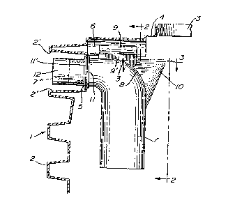
A mounting means for an elbow pipe in a septic
tank consisting of a keyway made in the top wall of the tank
and longitudinally aligned with a circular opening formed in
an end wall adjacent the top wall of the tank. The elbow
pipe has a key adapted for outward sliding engagement in the
keyway. The elbow pipe fits within a sealing gasket adapted
to snap into the circular opening of the end wall and its end
portion is threaded. A connector sleeve is screwed on the
end of the elbow to secure the elbow within the gasket and to
receive a drain pipe glued within the sleeve.


Claims

Note: Claims are shown in the official language in which they were submitted.

THE EMBODIMENTS OF THE INVENTION IN WHICH AN EXCLUSIVE
PROPERTY OR PRIVILEGE IS CLAIMED, ARE DEFINED AS FOLLOWS:
1. The combination of a tank with a pipe and
mounting means for mounting said pipe within said tank; said
tank comprising side walls, at least one end wall and a top
wall; an access orifice formed in said top wall; a circular
opening made in said end wall adjacent said top wall; a pipe
mounting means formed in said top wall exposed within said
tank and extending inwardly from said end wall and longi-
tudinally aligned with said circular opening; said pipe having
an outer end; said pipe being provided with a sealing means
at its outer end adapted to engage said circular opening; said
pipe further having a pipe mounting member complementary
said pipe mounting means.
2. The combination as defined in claim 1, wherein
said pipe mounting means is an elongated keyway open at its
inner end and said mounting member is a key adapted to slide
in said keyway.
3. The combination as defined in claim 2, wherein
said keyway is cross-sectionally T-shaped and said key is
also cross-sectionally T-shaped but in smaller dimensions.
4. The combination as defined in claim 3, wherein
said sealing means is an annular gasket having a central,
annular external groove adapted to receive the circumferential
edge of said circular opening.
5. The combination as defined in claim 4, wherein
said pipe is an elbow pipe having a fin projecting
from its bend and forming a funnel communicating with the
inside of said elbow pipe and in register with said access
orifice when said elbow pipe is operatively positioned
within said tank.

6. The method of mounting an elbow pipe within
a tank; the latter having an end wall, a top wall with an
access orifice, a circular opening made in said end wall
adjacent said top wall and an elbow pipe mounting means
provided in said top wall; said elbow pipe having a mounting
member complementary to said mounting means; a sealing
means at said outer end; said method comprising the steps of:
a) lowering said elbow pipe into said tank through
said access orifice; and
b) sliding said elbow pipe outwardly with said
mounting member engaging said mounting means while
inserting the outer end of said pipe through said circular
opening.

Description

Note: Descriptions are shown in the official language in which they were submitted.


FIELD OF THE INVENTlON iZ~95~
The present invention relates to septic tanks
and fixtures therefor, more particularly to an improved novel
way of mounting a pipe in a septic tank.
BACKGROUND OF THE INVENTION
Till now, connecting pipes and elbows for septic
tanks have been mounted either loose or with gaskets in holes
of the tank. The elbows were difficult to install within the
tank and the joints between the septic tank, the connecting
pipes and the elbows are often not leakproof.
OBJECTS OF THE INVENTION
In view of the above, it is a first object of the
pxesent invention to provide a pipe connector and elbow assembly
which is easily and quickly fittable to the wall and ceiling
of a septic tank in a completely leakproof manner.
It is another object of the invention to provide
an assembly of the above type, which is non-costly to produce.
Another object of the invention is to provide an
elbow which can be easily cleaned when plugged.
S~MMARY OF THE INVENTION
The above and other objects and advantages of the
present invention are realized according to a preferred
embodiment comprising a septic tank and a hollow elbow. The
septic tank has end walls, side wa]ls and a top wall having an
orifice and cover provided therein. One or both end walls
are formed with a circular opening immediately below the top wall.
The latter has, formed therewith, an elbow mounting means extend-
ing inwardly away from and lonsitudinally aligned with the
circular opening of the end wall.
0 The elbow has an outer end which is adapted to
engage the circular opening of the septic tank. The other sur-
face of the elbow adjacent its opening is provided with seal~ing
~/.~jr
, - 2 -

12795~3'7
means arranged to make a leakproof connection when the elbow
is in place
The upper surface of the elbow inwardly of the seal-
ing means is provided with an elbow mounting member which is
complementary to the elbow mounting means.
~ In order to secure the elbow to the septic tank,
a worker has simply to lower the pipe through the orifice
capped by the cover and, then, by sliding the mounting member
into the elbow mounting means, push the pipe until it engages
the septic tank end wall opening. The sealing means can be
installed in said opening either prior or after elbow insertion.
BRIEF DESCRIPTION OF THE DRAWINGS
The above will be clearly understood by having
referral to the preferred embodiment of the invention, illus-
trated by way of the accompanying drawings, in which:
Figure 1 is a side elevation of the invention,
the septic tank being vertically sectioned and partly shown;
Figures 2 and 3 are sectional views taken along
lines 2-2 and 3-3, respectively/ of Figure l; and
Figure 4 is an enlarged vertical section of the
connector and gasket in position on the tank, the latter
and a connecting pipe partially shown in dotted lines.
Like reference numerals indicate like elements
throughout the drawings.
DETAILED DESCRIPTION OF THE PREFERRED EMBODIMENT
Septic tank 1 has an end wall 2 which is horizon-
tally and/or vertically corru~ated and which merges with
both side walls (not shown) and a transversely-convex top wall
4 having an orifice 3 and a cover (not shown). The uppermost
two corrugations 2' have between them a circular opening
5 made in each end wall 2.
Outwardly of top wall 4 the upper part of tank

1;~97~iS~3~
1 is formed with the elbow mounting means disclosed above.
The means consists of forming top wall with an elongated
longitudinal keyway 6, which is cross-sectionally in the
general shape of a T and has a slot 6'.
A pipe elbow with a curved part 8 is adapted to
be supported under keyway 6 by a complementary T-shape key
9. The latter has a leg portion 9' slidable in slot 6' and
is rigidly secured to or integrally made with elbow 7. The
latter, as well as tank l, are preferably made of a thermo-
pl~asticr tank l preferably by rotary molding, and elbow 7
preferably by blow molding.
Inwardly of member 9, elbow 7 is provided witha fin lO, which may be used to displace the pipe elbow. As
shown in Figure 3, fin lO forms a funnel opened at the top and
communicating with the inside of elbow 7 through elbow side
opening 7'.
secause funnel-forming fin lO registers with tank
access opening 3, it is easy to clean elbow 7 through fin lO
and opening 3 by the use of a suitable tool, whenever elbow 7
becomes clogged.
The tank end wall opening 5 is provided with the
sealing means, consisting of an annular sealing gasket 11,
made of elastomeric material and which has a central annular
groove ll'. This annular groove is intended to receive the
circumferential edge of the circular opening 5 of end wall
2. Gasket 11 has inner spaced lips 11''.
Elbow pipe 7 has an outwardly-facing step 7'
followed by a tapered portion 7'', in turn followed by a smaller
diameter extension 7'" , the-latter being externally threaded
An inwardly-threaded connector sleeve 12 is screwed on
extension 7''' and secures elbow 7 in position with gasket 11
sandwiched between step 7' and sleeve 12. A drain pipe P is
-- 4

l~7ssa~
fitted and glued within sleeve 12. sOth ends of the tank
can be arranged with the system of the invention, one pipe
serving as an inlet and the other as an outlet.
This invention is applicable, inter alia, to the
septic tank described in applicant's Canadian patent No.
1l080,862,dated July 1, 1980, and also to holding tanks.

Representative Drawing
A single figure which represents the drawing illustrating the invention.
Administrative Status

2024-08-01:As part of the Next Generation Patents (NGP) transition, the Canadian Patents Database (CPD) now contains a more detailed Event History, which replicates the Event Log of our new back-office solution.

Please note that "Inactive:" events refers to events no longer in use in our new back-office solution.

For a clearer understanding of the status of the application/patent presented on this page, the site Disclaimer , as well as the definitions for Patent , Event History , Maintenance Fee  and Payment History  should be consulted.

Event History

Description Date
Inactive: IPC from MCD 2006-03-11
Time Limit for Reversal Expired 2003-01-29
Letter Sent 2002-01-29
Inactive: Late MF processed 2001-04-17
Letter Sent 2001-01-29
Letter Sent 1999-07-02
Grant by Issuance 1991-01-29

Abandonment History

There is no abandonment history.

Fee History

Fee Type Anniversary Year Due Date Paid Date
MF (category 1, 7th anniv.) - standard 1998-01-29 1997-09-25
Registration of a document 1998-02-27
MF (category 1, 8th anniv.) - standard 1999-01-29 1999-01-29
MF (category 1, 9th anniv.) - standard 2000-01-31 2000-01-27
MF (category 1, 10th anniv.) - standard 2001-01-29 2001-04-17
Reversal of deemed expiry 2001-01-29 2001-04-17
Owners on Record

Note: Records showing the ownership history in alphabetical order.

Current Owners on Record
UNION CARBIDE CHEMICALS AND PLASTICS CANADA INC, DIVISION WEDCO MOLDED PRODUCTS
3014593 NOVA SCOTIA COMPANY
Past Owners on Record
DENIS GUIBAULT
Past Owners that do not appear in the "Owners on Record" listing will appear in other documentation within the application.
Documents

To view selected files, please enter reCAPTCHA code :


To view images, click a link in the Document Description column. To download the documents, select one or more checkboxes in the first column and then click the "Download Selected in PDF format (Zip Archive)" or the "Download Selected as Single PDF" button.

List of published and non-published patent-specific documents on the CPD .

If you have any difficulty accessing content, you can call the Client Service Centre at 1-866-997-1936 or send them an e-mail at CIPO Client Service Centre.


Document
Description 
Date
(yyyy-mm-dd) 
Number of pages   Size of Image (KB) 
Claims 1993-10-18 2 54
Abstract 1993-10-18 1 14
Drawings 1993-10-18 2 45
Descriptions 1993-10-18 4 125
Representative drawing 2001-11-01 1 12
Maintenance Fee Notice 2001-02-25 1 176
Late Payment Acknowledgement 2001-04-19 1 171
Maintenance Fee Notice 2002-02-25 1 179
Fees 2000-01-26 1 27
Fees 2001-04-16 2 105
Fees 1997-09-24 1 39
Fees 1999-01-28 1 32
Fees 1997-01-23 1 28
Fees 1995-12-13 1 32
Fees 1995-01-18 1 33
Fees 1993-10-19 1 28
Fees 1992-12-01 1 23