Note: Descriptions are shown in the official language in which they were submitted.
798~3
HOIST FOR USE AT A MANHOLE
BACKGROUND OF THE INVENTION
This invention relates to a hoist for use
at a manhole of the type which can be used for raising
and lowering the person entering the hole.
Recent safety legislation has mandated
that it is necessary for persons entering manholes to be
attached to a suitable hoist so that they can be
recovered in the event of any difficulties being
encountered, for example poisonous fumes which can
accumulate in underground locations of this type.
A tripod hoist is available which includes
three legs which stand at angularly spaced locations
around the hole and converge to a central apex from
which a cable descends into the manhole. This device
however is generally unsatisfactory for a number of
reasons, including the high initial cost, the
unsatisfactory balancing condition and the obstruction
of the manhole by the aquipment which can interfere with
the person or other equipment being passed through the
hole. It is one object of the present invention,
therefore, to provide an improved hoist of this general
type. In addition various hoist type equipment is
available for use in various different circumstances.
- 2 - ~79863
Thus devices are proposed for use with lifting patients from
a wheelchair and in lifting engines from an engine
compartment of an automobile. However none of these devices
is suitable for use at a manhole and it has been necessary
for the present inventor to design a device which is
specifically suited and adapted for the particular purpose of
use as a hoist at a manhole.
SUMMARY OF THE INVENTION
According to an aspect of the invention there is
provided a hoist for use with a manhole comprising a
substantially planar horizontal base member and a swivel arm
member, the base member consisting of a pair of tubular side
struts, each side strut haing ground engaging means thereon
consisting solely of a pair of vertical ground engaging legs
arranged at respective ends of the strut extending downwardly
therefrom and mounted thereon for vertical adjustment, each
leg having a flat horizontal plate on its lower end, a cross
member interconnecting the side struts at a position offset
to one side of a center line of the side struts such that a
shorter portion of each side strut e~tends rearwardly of the
cross member and a longer portion of each side strut extends
forwardly thereform, the side struts and the cross member
lying in a common horizontal plane, and a vertically
uspstanding member welded on the cross member; the swivel arm
member consisting solely of a vertical tubular post portion
having means at an lower end thereof such that it can be
~'i
- 3 ~ ~798~-3
releasably mounted on said upstanding member for pivotal
movement about a vertical axis, a tubular jib portion welded
to the post portion so as to extend outwardly to one side of
the post portion such that an outer end of the jib portion is
a fixed distance from the upstanding member, a hand-operated
cable winch mounted on the post portion and a pulley mounted
on the end of the jib portion remote from the post portion
over which a cable from the winch passes to extend downwardly
from the end of the jib portion through the base member and
into the manhole, the upstanding member and the post portion
having cooperating means mounted thereon arranged to restrict
the pivotal movement of the post portion to an arc
substantially lying forwardly of the cross member.
Pceferably the base member is generally H-shaped
consisting simply of the side struts and the cross member
which is offset from the center line of the rectangle but is
positioned forwardly of the adjacent legs so that in use with
the legs sitting at the angularly spaced positions around the
manhole, the cross member is offset from the central axis of
the manhole but overlies a portion of the manhole adjacent
the side thereof. The simple H-shaped base member allows
full clearance between the side members and the cross member
to allow e~uipment and the person to pass through the large
area on the side of the cross member and between the side
members into the hole.
Preferably the swivel arm comprises simply a fixed
~;
- 4 ~ 986~
angle between the upwardly extending post portion and the jib
portion which is inclined thereto at an angle of the order of
60 so as to extend upwardly and outwardly therefrom to a
height sufficient to hold the winched man fully out of the
hole. It will of course be appreciated that the man will be
wearing a conventional harness which will be attached to the
cable so that when the cable is fully winched the man is held
supported from the end of the jib portion at a position which
he can be removed from the cable to one side of the manhole
even if he is incapacitated by an accident or the like. The
swivel arm is preferably formed of simple pipe construction
with a supporting brace at the angle between the post portion
and a jib portion.
Preferably the receiving portion at the cross
member is formed as a short length of pipe into which the
post portion can be inserted for simple swiveling movement
about the axis of the pipe. This swiveling movement can be
restricted to 180 in which the jib portion can rotate to
either side to lie parallel to the cross member and between
those extremes extends outwardly over the major portion of
the manhole.
~1
_ 5 _ ~7~3
With the foregoing in view, and other advantages as
will become apparent to those skilled in the art to which
this invention relates as this specfication proceeds, the
invention is herein described by reference to the
accompanying drawings forming a part hereof, which includes a
description of the best mode known to the applicant and of
the preferred typical embodiment of the principles of the
present invention, in which:
DESCRIPTION OF THE DRAWINGS
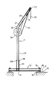
Figure 1 is a side elevational view of the hoist
according to the invention.
Figure 2 is a cross sectional view on an enlarged
scale of a portion oE the base member and receiving member.
Figure 3 is a top plan view of the hoist of Figure
1,
Figure 4 is an elevational view on an enlarged
scale of the end of the jib portion showing the pulley.
e~
8~.3
Figure 5 is a side elevational view of the end of
the jib portion showing an additional attachment in place of
the simple pulley of Figure 4.
~79~363
-- 7 --
DETAILED DESCRIPTION
The basic invention comprises a base
member 10 and a swivel arm 11 which are formed as two
separate pieces which can be disconnected and carried
separately for ease of transportion of the hoist device.
The base member 10 comprises a pair of
side struts 12 and 13 and a cross member 14 which
interconnects the side struts in the form of a H shape.
Each of the side struts has at each end thereof a
respective one of four legs 15 of a type comprising a
flat pad 15 which can sit on the ground and a screw
shaft 17 joining the pad to the side strut. The screw
17 passes through a female screw thread 18 in the side
struts with a suitable cranking mechanism indicated at a
head 19 on the top of the screw 17 to allow vertical
adjustment of the height of the pad 16 relative to the
end of the respective side strut.
Thus the four legs 15 are arranged at the
corners of a rectangle. The side struts 12 and 13 do
not extend straight along the side of the rectangle but
are cranked slightly inwardly at the junction with the
cross member 14 so as to reduce the unsupported length
of the cross member 14. The cross member 14 is offset
from a centre line of the rectangle thus defining a
3863
-- 8
larger area 20 on one side of the cross member than on
~he other side as indicated a~, 21 to define a working
area between the side struts 12 and 13 and forwardly of
the cross member 14 which is sufficient in size to
receive equipment to be passed through the hole and also
the person who can simply pass between the three parts
defining the area 20.
The offset of the cross member 14 is not,
however, sufficient to take the cross member beyond the
edge of the manhole so that any weight applied to the
swivel arm 11 is applied forwardly of the rearward most
legs as shown in Figure 3 to maintain the device
properly in balance over the hole which is indicated at
22.
Welded to an upper surface of the cross
member 14 is a pipe 23 which extends vertically upwardly
to define a vertical swivel axis for the swivel arm 11.
The swivel arm 11 comprises a vertical
post portion 24 and a jib portion 25 which is rigidly
connected to the post portion and extends upwardly and
outwardly therefrom at an angle of the order of 60 to
the horizontal. Both the post portion 24 and the jib
portion 25 are formed from pipe welded at the elbow
indicated at 26 and supported by a cross brace 27 in the
363
form of a web along the inside of the angle.
Turning to the enlarged view shown in
Figure 2, it will be noted that the inside diameter o~
the upstanding receiving pipe 23 is lightly greater
than the outside diameter of the pipe forming the
proposed portion 24 so that the latter is a slidin~ fit
inside the receiving portion and is maintained in the
required upright position but is rotatable about a
vertical axis defined by the pipe 23. The outside upper
end of the pipe 23 is cut down over 180 of its
periphery to form a step 23A at the rear of the portion
which cooperates with a lug 28 welded to the front of
the post portion 24 to restrict rotation of the post
portion to an angle of the order of 180. The swivel
arm can thus rotate as indicated at the arrow 29 through
180 from the position spacing sidewardly parallel to
the cross member 14 on either side of the receiving pipe
23 that is to a retracted position allowing full access
to the area 20 and in between those positions it lies in
the operative position overlying the manhole 22. A
winch 29 of conventional construction is mounted on the
post portion 24 for paying out and recovering a cable 30
which extends through an opening 31 in the underside of
the pipe forming the jib portion 25 to a pulley 32
63
-- 10 --
inside the end of the jib portion. The pulley i9
suitably mounted on a cross bolt 33 and is exposed at a
slot 34 so that the cable 30 can extend downwardly as
indicated at 35 for attachment to the harness of the
operative.
In the arrangement shown in Figure 5, the
pulley 32 is removed and an adaption device 36 attached
onto the pin 33 in its place. The adaption device 36
carries additional pulley 37 which can be used in place
of the pulley 32 together with a payout device 38 which
is attached to the device 36 by a pin 39. The payout
device is commercially available and is of a type which
pays out a cable 40 under tension and has an automatic
spring return biasing the cable 40 back into its
retracted position. The device 38 also acts to lock the
cable 40 when its speed of withdrawal exceeds a
predetermined maximum for example when the operative
falls. Thus the operative can be attached both to the
cable 40 and to the cable 30.
The two parts of the device comprising the
base member and the swivel arm are both formed from
aluminum material to provide sufficient strength at
lightweight so the device is readily removable and
transportable.
7~3863
-- 11 --
Since various modifications can be made in
my invention as hereinabove described, and many
apparently widely different embodiments of same made
within the spirit and scope of the claims without
departing from such spirit and scope, it is intended
that all matter contained in the accompanying
specification shall be interpreted as illustrative only
and not in a limiting sense.