Note: Descriptions are shown in the official language in which they were submitted.
~'~80130
This invention relates to trenching apparatus and to
the ~ormation of inground retaining walls.
In the erection of above-ground structures it is often
necessary to form inground retaining walls for use as a load
bearing foundation or about a site to be excavated, as a means
of retaining the earth about the excavation. Where such
e~xcavations are adjacent an existing structure the retaining
wall or walls along the excavation line adjacent the existing
building must be formed to resist soil pressures established
beneath the adjoining structure. In particular, such retaining
walls must be put in place so that the soil beneath the
adjoining structure will not collapse outwardly into the
excavation as the latter progresses. Walls of this type may
also be constructed to cut off ground water movement.
Various methods have been employed to form such walls
including ~rivlng 5heet plling along the excavation line to ~orm
a xetaining wall, and boring a closely ~paced row of holes and
casting reinforced concrete piles in the respective holes to
form the desired wall. If the latter process is used for
retaining walls, it is necessary to add substantial horizontal
strengthening to the row of piles to maintain their alignment.
It is also dif~icult to form such walls as watertight cutoff
walls. Continuous reinforced concrete walls provided excellent
supporting, retaining and/or cutoff walls. However to date, it
is generally not possible to form inground reinforced concrete
walls economically.
Techniques for the continuous excavation of trenches
of cross-section suitable for such retaining and/or cutoff walls
are available. A typical machine is the subject of Australian
Patent Application No. 41139/85 published on October 11, 1985
in the name of Foundation Technology (Aust) Pty. Ltd. Such
machines can continuously excavate a relatively deep trench
along an excavation line. However, their trenching capacity is
limited by flexural and machine weight considerations.
,y
,
lX8~130
Accordingly, while it may be posQible to construct trenching
apparatus which would excavate any desired trench, the size
of the machine neces~ary for normal inground retaining wall
trenching operations would render it impractical.
Furthermore, such trenching machines may incorporate an
arm supporting an endless chain carrying cutting teeth for
their trenching tools. The teeth generally project a
significant distance outward from the pivots of the chain, 80
that cuttin~ forces acting at a cutting tooth in a direction
along the line of the chain impose bending moments which tend
to flex the cutting chain in such a way a~ to increase the
cutting depth of the cutting tooth uncontrollably, resulting
in excessive loading on the cutting tooth, the chain and the
trenching machine. The problem could be alleviated by u~in~
a chain of much lon8er pit¢h, but thi~ approaoh would re~uire
the use of correspondin~ly lar~er chain sprocket~.
Such trenchin~ arms must be ~oroed ~orward in the
excavatiorl by advancing the machine to which the cuttinB arm
is attached. As the depth of excavation becomes greater,
this technique places large bending ~oments on the cutting
arm and its support structure, due to the increasing vertical
off~et between the centroid of the normal forces on the
cutting teeth and the line of action of the advance force at
ground level. This problem can be alleviated by u~ine an
advance system placed within tbe trenching ar~ below ground
level to force the trenching arm forward by engagin~ plates
with the sides of the excavation and ~orciny the trenchine
arm forward by pushing the plates rearward relative to the
arm.
It i8 an object of the present invention to alleviate
the above and other disadvantages and to provide iDproved
trenchin8 apparatus and methods of formin8 in8round retaininB
walls which will be reliable and e~icient in operation
Other objects and advantages of this invention will
~Z80130
he;reinafter become apparent.
With the foregoing and other objects in view, this
inwention resides broadly in trenching apparatus comprising:
a ~upporting base supported for longitudinal movement along an
excavation line; a carriage; mounting means for mounting the
carriage on the supporting base, the carriage being restrained
by the mounting means for longitudinal movement along the
supporting base; and a trenching arm assembly supported by the
carriage and operable to excavate a section of trench along the
lo excavation line as the carriage moves longitudinally along the
supporting base, the trenching arm assembly including a
trenching arm frame, the trenching arm frame supporting opposed
trench-engaging members which may be forced outwardly into
engagement with the opposed side walls of a trench, and
advancing means associated with the members ~or advancing the
trenching arm frame.
The supporting base may include skids whereby the
trenching apparatus may be moved along the excavation line or
it may include wheels moveable along rails alongside the
excavation line. Preferably however, the supporting base is in
the form of a crawler assembly and there are provided means for
driving the crawler assembly. It i8 al~o preferred that the
mounting means along which the carriage is moveable is in the
form of a platform having captive rails thereon for supporting
the carriage for longitudinal movement in the desired direction
whereby tilting said carriage will cause a corresponding tilt
in said trenching arm assembly. Of course the carriage could
be slidably mounted on the mounting means if desired and
separate retaining means could be utilized to secure the
carriage to the mounting means.
, ~
12~3013~
~ ref'erably, the trenching arm assembly i~ pivotally
connected to the carriage 80 that it may pivot about a
tlanQVer~e sub~tantially horizontal axi~ to enable it to be
rotated to a horizontal attitude for transport. If desired
hydraulic rams or the like may be u~ed to pivot the arm or it
may be lifted by a crane, either separate or mounted on the
trenching apparatus. Suitably, locking means are provided to
secure the arm in selected po~itions.
The pivotal connection between the trenching arm
assembly and the carriage may also include a slide mounting
whereby the vertical position of the operatively disposed
trenching arm relative to the pivot assembly may be adjusted
to enable the depth of cut of the trenching arm to be varied.
The carriage may be providet with drive means for
advancing it alorl~ the platform, Further advan¢ing means may
be as~ociated with a lower portion of the trenching arm
remote ~rom its pivotal connection to the carriage and
adapted for engagement with the side walls of the trench and
operable to advance the lower portion of the trenching arm
along the excavation line.
It is also preferred that the trenching apparatus be
provided with shield means trailed from said trenchin8 arm
a~sembly and engageable with the opposed walls of the trench
to prevent the latter from collapsing, said shield means
providing a clear space within the trench into whioh
reinforcement may be fed. The shield means may also support
concrete di~charge means through which concrete may be
discharged into the trench behind ~aid shield means.
Preferably the trenchin8 apparatus is constructed with
an elongate trenching arm which is movable between a raised
travelling position wherein the trenching arm iB aliened
generally horizontally alongside the supporting base to
enable its movement between sites and a lowered di~ing
position. The tren¢hing arm may be mounted B0 that it may be
~280~30
moved down~ardly into the earth to its desired excavation
depth at which it may be advanced forwardly along said
mountir.g means to form a ~ection of a trench. Generally, the
desired trench wall~ will be sub~tantially vertical within
preset tolerances and to this end, the trenching arm may be
mounted upon a platform which may tilt and be continuously
adjustable ~o as to retain the trenching arm vertical within
the desired tolerance~. Laser beam~ may be employed so as to
control the direction of the apparatus. The support platform
may be mounted over crawler track~ on adjustable rams 80 as
to maintain the platform level and thus hold the trenching
arm vertical
With the above deQcribed apparatus it is po~sible to
excavate a trench in a way which allows steel reinforcin8 to
be installed and ¢oncrete to be poured into the excavated
trench about the reinforcing exposed beyond a clear space
provided beyond the trenching arm, Thus an in8round
reinforced concrete wall may be ~ormed which can be excavated
on one xide to produce a permanent load bearing wall about
the excavation. Typical uses for this type of machine i~ in
high rise and low rise building, where a retaining wall is
de~ired during the construction ph~se as the basement is
excavated and then as a permanent load bearing wall when the
building is conRtructed to take the loads induced by the
building and surrounding ground pre~sure~. Other
applications are in bridge abutments, wharf and canal walls.
So that the trenching arm may exert a forward thrust on
the material to be excavated, a suitable mechanism may be
located inside the frame of the arm and enyagable with the
side or bottom walls of the trench to provide a forward
thrust. This may consist of a hydrsulic cylinder attached to
a linkage cechanism connected to side plates adapted, when
the hydraulic cylinder is activated, to force the side plates
into the side of the walls of the trench, and ~ub~equently
~Z80130
produce a force to thrust the trenching arm forwardly into
the 80i 1 to be excavated.
The trenching arm may be located at the top by a
mechani~m which allows the digger arm to be lowered into the
ground and removed from the ground. This may be done by a
rack and pinion mechanism. This mechanism may allow the
digger arm to be lowered to any predetermined point and held
there if desired. The mechanism may also be connected to a
la~er beam control to ensure that the trenching arm maintains
a consistent excavation level. The mechanism which support~
the trenching arm may also be capable of rotating with the
trenching arm to allow the trenching arm to lay horizontally
in order that it may be transported. In this respect a
curved rack and pinion arranBement msy be u~ed. This allows
the trenchine arm to be withdrawn from the ground and then
rotated and locked into the horizontal position ~or
transportstion. The same mechanism may also allow the
trenching arm to remain vertical when in operation
irre~pective of the attitude o~ the mountin~ base. The
mounting base may be in the form of a pneumatic-tyred
chassis,
The deck of the machine may be hinged around the
supporting base on the side adjacent the trenching arm and
the other side of the deck may be mounted on hydraulic
cylinders, such that the deck of the machine may be
maintained level. Adjustment of the hydraulics could be
automatic. The deok of the machine may house the engine,
cooling sy~tem, hydraulic sy~tem and any micro-processor
equipment to control the machine, such that as far as
possible it operate~ automatically.
In another aspect, this invention reside broadly in a
method of forming a reinforced concrete retaining wall
including:- continuously formin~ a trench snd si~ultaneously
maintainin8 the trench wallQ sgainst ¢ollapse over a section
~Z80~30
thereof behind the leading end wall of the trench with a
clear space therein into which reinforcement may be in~erted;
inserting reinforcement into said clear space, and pumping
concrete into the trench rearwardly of the clear space to
fill the trench as said clear space advances along the trench
being formed.
The above method may be performed by excavating the
trench into bedrock 80 that a footing of the retaining wall
is keyed therein and thereby retained in place.
In order that thi~ invention may be more readily
understood and put into practical effect, reference will now
be made to the accompanying drawings, wherein:-
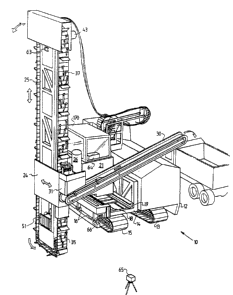
FIG 1 is a perspective view of a preferred form of
trenching apparatus;
FIG 2 i~ an end view of the trenching apparatus;
FIG 3 is a plan view of the trenching apparatus;
FIG 4 is a part-sectional view taken along the line 4-4
of FIG 3;
FIG 5 i8 a broken aw y side view of the trenching arm;
FIG 6 is a ~ide view of portion of the trenching chain
showing the arrangement of the cutting teeth;
FIG 7 is a plan view corresponding to FIG 6;
FIG 8 i8 a transverse section through a trenching arm
illustrating one form of the advancing mechanism;
FIG 9 illustrates one form of dirt conveying flap for
the trenching chain and the associated cleanin8
apparatus;
FIG 10 iB a diagrammatic plan view illustratin~ one
method of introducing concrete and reinforoing into the
trench;
FIGS 11 and 12 illustrate a further form of advancin~
mechanism;
FIGS 13 and 14 illustrate yet another form of advancin8
mechanism, and
lZ8~13~
FICS 15 and 16 illu~trate a further form of advancing
mechanism.
The trenching apparatus 10 include~ a crawler base
a~embly ll which supports a power-pack 12 above one crawler
track 13 for supplying power to the various hydraulic rams
and motors incorporated in the apparatus, and a carrier
assembly 14 above the other crawler track 15. The carrier
assembly i~ pivotally connected at 16 to the crawler base
assembly for pivotal movement about a longitudinal tilt axis
outwardly of the crawler track 15 and hydraulic rams 17 are
provided to selectively tilt carrier a~sembly 14. The latter
ha~ a pair of captive longitudinally extending rails 18 and
l9 which have upper and lower rail surfaces which engage
about wheels 20 mounted on a ¢arria~e 21 which is re~trained
by the rail~ 18 and 19 for lonyitudinal motion therealone
above the crawler track l5.
The carriage 2l is provided with a central bearing
assembly 22 which supports a transversely extending pivot
tube 23 which extends outwardly beyond the crawler base
assembly ll and connects fixedly to a mounting sleeve
assembly 24 through which the trenching arm 25 is
reciprocable. The bearing assembly 22 retains the pivot tube
23 for rotation about a transverse horizontal axis and it
permits limited free axial movement of the pivot tube and
thus the trenching arm, 80 that in use the latter may veer
slightly away from the de~ired excavation line as a result of
a side force exerted by an obstruction iD the excnvation and
thus prevent the impo~ition of excessive forces on the
apparatus.
Hydraulic rams 26 connected between the carriage 21 and
the mountin~ sleeve assembly 24 may be actuated for pivotin~
the lstter 80 that the trenching arm assembly may be pivoted
between itB substantially vertical operative trenchin~
po~ition, as illustrsted, and a horizontal position at which
iZ80~30
it lies alongside the carrier assembly for transport
purpose~. A~ can be seen in FIG 4, the pivot tube 23 i8
provided with a notched collar 27 in which pawls 28 may
engage to hold the trenching arm 25 in either its operative
trenching position or its raised travelling position.
A dirt conveyor 30 i8 supported on the carriage 21. The
conveyor 30 extend~ from a lower po~ition, adjacent an outlet
chute 31 provided on the mounting sleeve assembly 24 and
through which dirt may ~pill from the trenching chain 3~,
upwardly across the power pack ~or di~charging dirt to one
side of the excavated trench.
Referring to FIGS 5 and 6 it will be seen that the
trenching arm 25 includes a trenching arm frame 32 which
support~ upper and lower pairs of sprockets 33 and 34
respectively, about whioh the ~eBmented trenchin8 chain 36
extends. Intermediate rollers 3B are provided for ~upporting
the chain between the pairs of eprockets 33 and 34 and
outting teeth 37 are mounted in staggered relationship on
regularly spaced segments of the chain 35. The lower
sprocket~ 34 are arranged 80 that bottom run of the trenching
chain extends upwardly and rearwardly from the front lower
sprocket to the rear lower sprocket. The upper ~prockets 33
are driven by independent hydraulic motors 43 and 44. The
trenching arm frame 32 is provided with a spaced pair of
guide rollers 38 and 39 which engage tracks 47 on the
outermo~t face of the trenching arm frame and driven 8ears 40
and 41 which engage racks 42 on the inner ~ace o~ the
trenching arm frame 32 whereby the latter msy be moved
through the mounting sleeve assembly 24 80 as to adjust the
depth of excavation.
The carriaee 21 is connected to the carrier assembly 14
by a chain drive assembly 45 having a chain 48 which extends
from the carriage about a leading sprocket driven by the
motor 46 mounted on the carrier assembly 14 adjacent the
~280130
front of the machine and an idler sprocket 49 mounted on the
carrier as~embly adjacent the rear. The hydraulic motor 46
i 8 adapted to be actuated to advance the carriaee 21 alon8
the rails 18 and 19 ~o a~3 to advance the trenching arm for
6 excavati on purposes.
The trenchin8 arm as~3embly 25 i~ also provided with
advancing mechanism 50 and 51 at spaced positions
intermediate its length which may be engaged with the side
walls of an excavated trench 80 as to push the lower portion
10 of the trenching arm 25 forwardly into cutting arrangement
with the face of the excavation. As shown in FIG 8, each
advancing mechanism 50 and 51 includes a pair of side plates
53 and 54 supported by a linkage 55 actuated by a hydraulic
ram 56 whereby the side plates 53 and 54 may be forced
15 outwardly into enga8emen'c with the side of the trench.
The side plates are provided with barbs 57 to facilitate
positive enga8ement with the ~ide walls of the trench and the
arrangement of the interconnected trailin~z links 58 is such
that initial extension of the hydraulic ram ~orces the side
20 plates apart until they engage the side wall~ of the trench
whereafter further extension of the ram 56 will ¢ause
relative longitudinal movement between the side plates 53 and
54 and the trenching arm frame 32 80 as to push the trenching
arm into cutting relationE~hip with the advancing ~ace o~ the
2~ excavation. The side plates 53 and 54 are interconnected by
a sprin~ 59 such that a preload is applied between the ide
plates 53 and 54 and the side walls o~ the trench.
Retraction of the ram 56 will draw the side plates 53 and 54
away from the side walls of the trench and move them to their
30 forward po~ition.
As shown in FIG 2 the front end wall of the ~ountinR
sleeve assembly 24 is apertured at 61 to peroit exoavated
dirt to pa88 thereto into the ohute 31 for di~char~te at the
opposite side of the trenching apparatus along the conveyor
1280~30
a~em~ly 30.
~ irt removed from the advancing face of the trench falls
into the gap between the trench walls and the trenching chain
3~. It falls onto dirt conveying flaps 60 which are attached
to the trenching chain at intervals. The upward movement of
the front run of the trenching chain 35 raises these dirt
conveying flap~ 60 and the dirt upon them out of the
excavation. Formed guide~ in and below the mounting sleeve
a~embly 24 act as a continuation of the trench to contain
the dirt re3ting on the dirt conveying flaps 60 until it
reaches a discharge port 61 in the mounting sleeve 24 above
the discharge conveyor 30 from whence it fall~ onto the
discharge conveyor 30 through the chute 31. Dirt which
remain~ on the dirt conveying flap~ or the trenchin~ chain is
1~ removed by rows of cleaning sprinys 62 attached to the
mountin~ sleeve 24. These cleanin~ springs 62 are adapted to
scrape along the trenching chain 35 in their normal operating
position and to spring away from the trenching chain 35 when
contact is made with a diggin~ tooth 37 or a dirt conveying
~lap 60.
The transverse inclination of the trenching arm i~
monitored by means of an electronic level sensor 63 ~ounted
in the trenching arm frame 32. The output from this sensor
is fed to a control computer 64, which compares the measured
inclination with the desired inclination and if neoessary
actuates the platform tilt cylinders 17 to bring the
trenching arm back to the desired inolination. A similar
system is employed to control the inclination of the
trenching arm about the axis of the pivot tu~e 23. The
output of the computer control~ the relative speed of the
carriage drive and the trencher arm sdvancing mechanism to
maintain the trenching arm at the desired inolination. The
ali~nment of the trenching apparatus with re~pect to the
desired line of the trench i8 onitored by settin8 up a laser
1280130
beam transmitter 65 on a line parallel to the excavation line
of the trench and monitoring the points of inter~ection of
the beam and two laser beam detectors 66 and 67 mounted near
the front and rear of the machine. The drive motors 68 for
the crawler tracks 13 and 15 are also controlled by the
computer 64 to correct any errors that are detected by the
system. This may be achieved after the carriage 21 has
travelled the full len~th of the carrier and before the
commencement of excavation of the next section of trench.
Accordingly, the trenching apparatu~ 10 may excavate a zig-
zag path which approximates a straight line. Alternatively,
the drive motors 68 may be operated as required during the
excavation process to produce frequent small corrections to
the direction of the excavation.
As shown in FIGS 6 and 7, the trenching ohain assembly
70 consi~ts of an endless chain 71 to which a plate 72 i8
attached. The plate 72 carries a toolholder 73 in whioh a
detachable cutting tool 74 i8 mounted. A braoing bar 76 is
ri~idly attached to the plate 72 carrying the toolholder 73
and extends in a direction along the endless chain 71
rearward from the cutting tool to contact a trailing plate 76
which i8 attached to the endless chain 71 behind the plate 72
when the chain is flat. The shape of the bracing bar 75 is
such that it passes around the chain ~uide sprookets at a
smaller radius than the tip of the cutting tool 74, 80 that
it doe~ not contact the trench face. The side o~ the bracing
bar 75 facing the trailing plate 76 is relieved to ensure
that contact between the bracing bar 75 and the trailing
plate 76 occurs towards the rear of the trailing plate 76.
~e side of the bracing bar 75 facing the trailing plate 76
i~ also chamfered to reduce the possibility of excavated
material lodging between the bracin~ bar 75 snd the trailin~
plate 76. Idler wheels 77 run a8ainst the back of the ohain
71 to force the cutting tool 74 aRainst the face of the
128~13~
excavation 78,
FIC 10 illu~trates one method of introducing reinforcing
and concrete into the trench rearwardly of the trenching arm
25, For this purpose the latter i~ provided with trailine
connector~ 160 for connecting shields 161 and 162 thereto,
whereby the shields eng~ge opposite walls of the trench and
provide a clear space therebetween into which rein~orcments
163 and 164 may be dropped. The reinforcements are fed
through the gaps between rollers 165 and 166 and guides 167
snd 168 on the trailing ends of the shields. As
reinforcement is fed into the trench between the rollers and
~uide, new sections may be dropped into place between the
~hield. A concrete discharge chute 169 fed by a Auitable
¢oncrete pump i8 used to continuQusly dischar8e oonorete into
the trench about the rein~orcment~. The rollers 165 and 166
and the 8uides 167 and 168 de~ine a ~mall gap therebetween
through whioh little ooncrete seeps 80 that the spaoe into
which reinforcements are fed is kept largely clear.
In u~e, the trenohing apparatus is driven to the site
and the trenching arm 25 i~ aligned with the excsvation line.
It is then actuated and moved vertically into engagement with
the earth to be excavated until it has reached the required
depth which may be up to eight metres. The carriage 2~ is
initially arranged in its rearmost position on the rails 18
and the trenching apparatus 10 is positioned 80 that movement
o~ the carriage 21 along the rails 18 and 19 will carry the
trenching arm 25 along the excavation line, A portion of the
tre~h i8 excavated by forcing the carria8e 21 alone the
rails to its forward most position and by simultaneously
actuating the advancing means 50 and 51 provided in the
frames of the trenching arm 25. The crawler traoks 13 and 15
are then actuated and the crawler base assembly i8 moved
forwarl alongside the excavation line 80 that the carriage is
again po~itioned at the trailing ends of the rails 18 and 19.
~Z80130
Thi~ proc~ is continued until the de~ired trench ha~ been
formed, Of course at each move of the supporting base, the
latter may be aligned to correct runoffs of the portion of
the trench Just excavated. Furthermore, the hydraulic rams
17 may be actuated to vary the tilt of the excavation arm
relative to the supporting base 80 that the excavation arm
can be maintained vertical or at a selected inclined
position. Automatic control apparatus may be provided to
maintain the desired control over the trenching arm and
suitably an operator's cab 170 is supported above the
carriage 21 80 that an operator can maintain a olose visual
inspection of the trench being excavated.
When the apparatus is excavating, the chain 71 is driven
parallel to the face 78 to be cut, and forced into the face
78 by the idler wheels 7~. Thi~ impose~ foroe8 on the
outting tool 74 which produce a moment tending to rotate the
tool holder 73 backwards by flexing the chain 71. This
moment is resisted and the rotation of the chain link is
limited by contact between the bracing bar 7~ and the
trailing plate 76. As shown in FIGS 9 and 10, the
reciprocating plate advance assembly 90 comprises plates 91
attached to pivot blocks 92 which are pivotally attached to
slide blocks 93 by pivot pins 94. The slide blooks 93 are
free to slide transversely in the slots 95 in the traverse
blocks 96. The traverse blocks 96 are free to slide
longitudinally in guides 97 attached to the trenching arm
frame 98. The traverse blocks 96 are connected to the
trenching arm frame 98 through the upper $1uid actuator 99
and the lower fluid actuator 100. One pipe 101 of the fluid
supply system i~ connected to the full pi~ton area ~ide of
the upper fluid actuator 99 and the second pipe 102 i8
connected to the rod side of the lower fluid actuator 100,
The rod side of the upper fluid f~,ctuator 99 and the full
piston are~ side of the lower fluid actuator 100 are
i28~130
intercorlnected by a pipe 103. The relative sizes of the
upper fluid actuator 99 and the lower fluid actuator 100 are
such that the fluid displaced from the rod side of the upper
fluid actuator 99 by a certain extension of the upper fluid
actuator 99 causes an equal extension in the lower fluid
actuator 100 when applied to the full piston area side of the
lower fluid actuator 100. The pusher plates 91 are extended
and retracted laterally by fluid actuators 104 which are
attached to the pusher plates~ 91 through brackets 105 and
clevis pins 106.
The soft-soil advance system 110, which is shown in FIGS
13 and 14, carries within a frame 111, fixed within the
trenching arm, ~ carriage 112 slidable longitudinally within
the frame 111 on slides 113. Plates 114 are slidable
16 laterally within the ¢arria8e 112 and con~trained to move
longitudinally with the carriage 112. The plates 114 are
attached to lateral aotuators 115 to extend and retract them.
The carriage 112 is attached by longitudinal actuators 116 to
the frame 111. The plates 114 are restrained from excessive
lateral travel by limit pins 117 fixed in the carriage 112
and engaging with slots in the plates 114.
The endless-chain advance system 130 illustrated in FIGS
15 and 16 comprises a frame 131 fixed within the trenching
arm, with l~teral actuators 132 connected between the frame
131 and the carriers 133. The carriers 133 support bearings
134 in which shafts 135 may rotate. The shafts 135 carry
sprockets 136 which engage with endless chains 137. ~lats
138 are attached to -the endless chains 137. Pressure plate
13g i8 attached to carriers 133 and disposed on the inner
side of the outer run of the endless chains 137. Drive is
provided by one or more rotary actuators 140 mounted to the
carriers 133 by brackets 141 and couple~ to the shaft8 135 by
couplin8s 142.
To advance a trenching arm to which it is fitted, the
1280130
reciprocating plate advance system is utilised by energiqing
the lateral actuator~ 104 to retract the plates 91 away from
the cideq of the excavation 107 while the longitudinal
actuators 99 and 100 draw the carriage 96 together with the
slide~ 93 and the plates 91 forward relative to the frame 97.
The lateral actuator~3 104 are then extended to bring the
plates 91 into contact with the walls of the excavation 107
and the longitudinal actuators 99 and 100 are e~nployed to
force the trenching arm forward relative to the plates 91
which remain ~3tationary in the excavation. The series
arrangement of the longitudinal actuatorx 99 and 10û and
their relative piston area~ ensure that the extension of both
cylinderE3 i~ the same 80 that the carriage 96 will not tilt
and bind the slides 97.
In order to advance a tren¢hing arm in which it is
installed, the soft-soil advance ~ystem iB utilised by
employin~ the lon8itudinal actuators 116 to pull the carriage
112 forward in the frame 111 with the lateral aotuators 115
retracted to withdraw the plates 114 within the profile of
the frame 111. The lateral actuators 115 are then extended
to force the plates 114 into the side of the excavation 118.
When the plates 114 have penetrated a suffi¢ient distance
into the 8i de of the excavation 118 to provide resistance to
lonS~itudinal movement of the plates 114 relative to the side
of the excavation 118, the longitudinal actuators 116 are
energised to force the frame 1~1, and thus the trenching arm,
forward in the excavation. When the lon8itudinal a¢tuators
116 are extended, the lateral actuators 115 are retracted to
withdraw the plates 114 from the side of the excavation 118
and the cycle is repeated.
To advance a trenchinR arlD in which it is installed, the
endless chain advance system is extended from the trenchin~
arm frame 131 by the lateral actuators 132 until the outer
run of slats 138 is forced a8ainst the side of the excavation
13~
143 by the pressure plate 139. The rotary actuator 140 is
then energi~ed to rotate the sprockets 136 and move the outer
run of the chains 137 and slats 138 backwards with respect to
the frame 131, propelling the trenching arm forwards.
It will of course be realised that whi1e the above has
been given by way of illustrative example of this invention,
all such and other modifications and variations thereto as
would be apparent to persons skilled in the art are deemed to
fall within the broad scope and ambit of this invention a8 i8
defined in the appended claims.