Note: Descriptions are shown in the official language in which they were submitted.
lZ8~)2;28
20104-80g6
The invention relates to a digital radio transmission
system comprising a plurality of base stations and mobile stations
arranged in a cellular network and wherein messages to be
communicated between each base station and the respective mobile
stations assigned thareto are transmitted over respective
communication channels.
There are three known basic methods for sending messages
over a transmission medium (e.g. transmission line, radio
channel): these are code-division multiplexing, frecfuency-division
multiplexing and time-division multiplexing.
In the code-multiplexing method the different messages
sent over a common transmission medium ara imposed by, for
example, baseband modulation on a carrier and the resultant
narrow-band signal (narrow in relation to the bandwidth of the
channel) is spectrally spread over the channel bandwidth by
multiplex modulation using a codeword that characterises the
receiver.
Recognition of the signal takes place not by time-
division or frequency-division selection but on the basis of the
spectral coding. The multiply stacked spectrally-coded messages
in the code-division multiplex channel are selected in the
receiver on the basis of this allocated codeword.
In the frequency-division multiplexing method the whole
bandwidth available for message transmission is divided into
narrow frequency bands, each o~ which corresponds to one message
transmlssion channel. This narrow frequency band is at the
disposal of th0 user for the duration of the message transmission.
z2a
2010~ ~0~6
In the time-division multiplexing method each user has
available to him the whole bandwidth of a single transmission
channel but only for short intervals of time. The oharacters or
sequences of characters of various users are interleaved and are
sent out with a correspondingly higher bit rate, the time channel
allocated to each user being periodically repeated with the
duration of the frame period.
From DE-OS 2S 37 683 a radio transmission system with
base stations and mobile stations is known, in which different
channel access methods are used with asynchronous tlme-division
multiplex, code-division multiplex and frequency-division
multiplex.
For codeword synchronization incoherent carrier
demodulation is used. ~ code generator consecutively generates
one of the nine differenk codes which characterize the base
stations. After this code has been synchronized with the
reception signal, the intermediate-frequency signal is multiplied
by it, thereby transforming the broad spectrum into the message
bandwidth. The received message can then be recovered by means
of, for example, a DPSK demodulator. For the synchronization the
message is prefixed by a characteristic code pattern with a length
of for example 15 bits.
Also known are combinations of the aforesaid methods and
their application in a digital radio transmission system. For
example, in "Nachrichtentechnik, Elektronik + Telematic 38 (1984),
Vol. 7, pages 264 to 268" a digital radio transmission system is
described in whlch the time-division multiplex method is used in
~28~2~:8
20104-~096
combination with spectral coding, but in which the various users
are not separated by means of the code-division multiple~ methocl.
In the time channels for speech and/or data ~ransmission (TCH
communication channel) a bit sequence for establishing the
synchronism, a frame-synchronization word and the bit sequence oE
the message itself are transmittecl one after the other. The time
channels for message transmission (3 x 20 TCH) are arranged with
organization channels (3 CCH) to form a time-d.ivision multiplex
frame with a duration of 31.5 msec. If the messaye to be
transmitted is a speech signal, adaptive delta modulation can be
used for analog/digital conversion. ~ code is superimposed on the
resultant message characters (bits) in the sender. It has proved
advantageous to group the individual message bits into blocks of
four bits each and to spread the resultant blocks with an
orthogonal alphabet. The spreading factor used is a compromise
designed to combine the advantages of band spreading with the
requirement to use the frequencies economically.
A message transmission method has also been proposed
tsee U.S. Patent 4,697,360) whereby a different modulation system
is used for the forward and reverse directions of the message
transmission channel. For message transmission the mobile
stations use one of a multiplicity of communication channels. In
the direction from the base station to its satellite mobile
stations each communication channel is separated by bandspread
modulation.
The spread communication channels are superimposed on
each other and the resultant broadband sum signal is transmitted
1.28~ 8
2010~ ~096
in a common frequency band. In the direction from the mobile
stations to the base station the messages are transmitted in
separate narrowband frequency channels.
For speech transmission from the base station to the
mobile stations the bandspread moclulation used is selected by the
base station and communicated to the mobile station when building
up the communication link. For the transmission of signalling to
the mobile stations allo~ted to the base station, a common
bandspread modulation is used for all mobile stations in the
direction from the base station to the mobile stations.
To distinguish between base stations configurated in
neighbouring transmitting cells, these stations transmit to the
mobile stations in different frequency bands. The base stations
are provided with narrowband receivers which, during operation,
can be switched to several different frequency channels. The
number of switchable transmitting frequencies in the mobile
stations is smaller than thè number of switchable receiving
frequencies in the base station. For example, in the base station
it is possible to switchover to 1,000 frequencies, whereas in the
mobile station it is possible to switchover to 40 frequencies.
In each base station the receiving frequencies used are
organized in order to optimize the interference situation. In the
event of reception disturbances the relevant connection from the
mobile station to the base station is switched to another
undisturbed frequency channel to which both the base station and
the mobile station can changeover. The receiving connection in
the base station to the public telephone system continues to take
. ,
~:8(~228
2010~-8096
part in the connection.
The object of the invention is to form communication
channels in a digital radio transmission system in such a way that
it is possible to adapt to inhomogeneous traffic densities and to
cut costs for the transmitter in the base station and in the
receiver in the mobile station.
This object is achieved in accordance with the invention
which provides in a digital radio transmission system comprising a
plurali-ty of base stations and mobile stations arranged in a
cellular network and wherein messages to be communicated between
each base station and the respective mobile stations assigned
thereto are transmitted over respective communication channels,
the improvement characterized in that each base station comprises
multiplexing means for multiplexing messages to be transmitted
from such base station to the mobile stations assigned thereto by
a combination of three different modes of multiplexing, such modes
including time-division multiplexing of respective time slots in
successive time frames, code-division multiplexin~ of such time
frames in accordance with respective codewords~ and frequency-
division multiplexing of such code division multiplexed timeframes at respective carrier frequencies, the respec~ive base
stations being identified by employing respective combinations of
said codewords and said carrier frequencies; and each mobile
station comprises multiplexing means for multiplexing messages to
be transmitted from such mobile station to the base station
assigned thereto by at least one of said modes of multiplexing.
By the use of bandspread modulation in the transmission
3b
~,:
Z~8
PHD 85337 4 10.07.1986
direction from the base station to the mobile stations multi-paths can
be resolved and evaluated and interferences largely avoided. When
different codes and the same frequency band are used in the various
cells of the digital radio transmission system (separation of
communication channels in the cells of a cluster by code multiplexing)
the same frequency can be repeated more often in the cell structure than
in a straight-forward frequency-division multiplex system. In this way
the transmission procedure maXes more economical use of available
frequencies.
Through the use of different codes in the cells of a
cluster (separation of the communication channels of mobile stations
within the same cell by code multiplexing) additional communication
channels are made available within a cell.
Through the use of different frequency bands with a
bandwidth of suitable flexibility for the radio network planning, it is
possible in neighbouring cells and also within a particular cell of a
digital radio transmission system in accordance with the invention to
adapt effectively to inhomogeneous traffic densities. This is done in
the first place by forming large radio cells for low traffic densities
and small radio cells for high traffic densities, and on the other hand
by employing several frequency bands within a high-density cell. The
use of this frequency-division multiplex method (channel sets) makes it
easier to switch from large to small cells. In cells with very high
traffic density several channel sets can be operated with the frequency-
division multiplex method (communication channels with the same codeset) so that the formation of very small cells can be avoided.
By using the time-division multiplex method additional
communication channels can be created in each code level, so that the
transmission capacity in the digital radio transmission system can be
further increased. In this way fewer transmitting devices are needed in
the base station than in the case of a pure frequency-division multiplex
system.
In both transmission directions of the digital radio
transmission system different combinations of multiplexing methods are
used for the grouping of communication channels . The message to be
transmitted can also be included in the communication channels by using
a combination of code multiplexing, time-division multiplexing and
~8~Z28
PHD 85337 5 10.07.1986
frequency-division multiplexing, in a transmission system in which
transmission takes place in only one direction. By applying the code-
multiplexing method a transmission system that makes economical use of
frequencies is then obtained when the signals all arrive at the receiver
in synchronization and with the same power, which can be done in
transmission from a stationary base station to each individual mobile
station.
The formation of the communication channels in a digital
radio transmission system is described in more detail in the following
with reference to the Figures, in which :
Figure 1 shows the multiplexing within one radio cell,
Figure 2 shows the frequency repetition in the cell
structure for the three different code sets,
Figure 3 shows the frequency repetition in the cell
structure for four different code sets,
Figure 4 shows a block diagram of the transmitting part
of the base station and
Figure 5 shows a block diagram of the receiving part in
the mobile station.
In a digital radio transmission system permanent base
stations BS are arranqed in a cellular configuration. To each base
station BS a number of radio communication channels are allocated, over
which messages are transmitted to mobile radio stations MS.
In the two transmission directions different combinations
of multiplexing methods are used for grouping the communication
channels. In the direction of transmission from the base station BS to
the mobile stations MS the message to be transmitted (speech or data) is
introduced into the communication channels using code-division
multiplexing, time-division multiplexing and frequency-division
multiplexing methods. For this purpose the base station BS is provided
inter alia with a TDM multiplexer 3, a codeword generator 5 and a
synthesizer 9 (see Figure 4). In the mobile station MS the
communication channels of the received digital signal are separated
using the code-division multiplexing, time-division multiplexing and
frequency-division multiplexing methods. For this purpose the mobile
station ~S is provided inter alia with a synthesizer 19, correlators 24
and 25 and a TDM demultiplexer 31 (see Figure 5). For the direction of
~8B22~3
PHD 85337 6 10.07.1986
transmission from the mobile stations MS to the base station BS the
transmission takes place in separated narrowband frequency channels. In
the following a description will be given of the multiplexing performed
for the direction of transmission from the base station BS to the mobile
stations MS.
A base station BS has for example at least one set of
channels consisting of 32 communication channels. The indi~idual
communication channels for the different mobile stations MS in a set of
channels are separated from each other by different bandspread codewords
(CDMA) and/or different time slots (TDMA). Figure 1 shows three of such
sets of channels, and in the example shown the channel sets 1 and 2
belong to the same cell and channel set 3 belongs to a neighbouring
cell. The characterization of the individual communication channels
(channel identification) is illustrated in Figure 1 by the sequence of
three-digit numbers. The first digit represents the number of the
relevant time slot, the second digit the codeword used, and the third
digit the number of the relevant carrier frequency. The grouping of the
communication channels in the direction of transmission from the base
station BS to the mobile stations MS is effectuated by the consecutive
methods of time-division, code-division and frequency-division
multiplexing. This preferred sequence facilitates the implementation of
the sending and receiving devices in the digital radio transmission
system.
A channel set is built up for example by grouping
together several time slots, each of which contains the information for
one particular user, to form a time-division multiplex frame. In Figure
1 the time-division multiplex frame comprises four time slots, e.g.
communication channel 1.1.1 to 4.1.1.
Next the information of such a time-division multiplex
frame is spread with suitably chosen codewords, which make it possible
to transmit simultaneously several time-division multiplex frames with
the same carrier frequency. The spreading of each of these time-
division multiplex frames is done with a codeword which in this set of
channels is allocated to this special time-division multiplex frame
only. This means on the one hand that within a channel set each time-
division multiplex frame contains for the spreading operation a specific
codeword that differs from those of the other time-division multiplex
2~8
PHD 85337 7 10.07.1986
frames, and on the other hand that the information in the time slots of
a time-division multiplex frame is spread with the same codeword.
In the embodiment shown in Figure 1 eight different
codewords per channel set are used, that is to say a channel set
contains eight different time-division multiplex frames each with four
time channels, together totalling 32 communication channels per channel
set.
By providing selected code symbols for the spreading
operation, as for example pseudo-rando~n, orthogonal or quasi-orthogonal
codewords, it is possible at the same time to transmit messages in code-
division multiplex. The eight individual spreading codes show a spread
of 31, that it to say a length of 31 chips. All code-division multiplex
channels are thereby transmitted from the sender of the base station BS
with the same power and synchronously in time. By using four symbols in
each code-division multiplex channel (the four symbols can for example
be represented by two antipodal codewords) it is possible to combine two
bits of the useful signal to form one symbol. This has the effect of
halving the symbol rate as compared with the bit rate of the baseband.
For the coding of the baseband signal and for synchronization there are
six different symbols available, two of which are used exclusively for
the synchronization. If eight individual spreading code levels are
formed with four time-set channels, 32 communication channels of for
example 16 kbit/s can be transmitted, which, after code-division
spreading, are modulated on a common RF carrier. When four-phase
modulation is used, the transmission of 32 communication channels takes
e.g. a bandwidth of 1.25 MHz. The time-stacking and hence the number of
communication channels per spreading code level depends on the bit rate
needed for each message transmission channel.
I'he grouping of the communication channels in the digital
radio transmission system in accordance with the invention offers
several advantages. These are :
- reduction of Rayleigh fading effect,
- avoidance of intersymbol interferences,
- economic use of frequencies,
- flexible and easy adaptation to different traffic densities,
- simple extensibility of the system,
- flexibility in re-use planning,
~2.80;;!.28
PHD 85337 8 10.07.1986
- simple frequency coordination with other countries or systems.
Due to the combination of every two bits to form one of
four possible symbols, the symbol duration of 25 ~s remains sufficiently
long to avoid intersymbol interference caused by multipath reception,
while on the other hand the outlay on the receiving hardware for the
correlator system is low. The 16 spreading codes used within one base
station BS to separate the code levels are for example orthogonal pairs,
while the different synchronization symbols in several base stations BS
with the same carrier should show minimum cross-correlation products for
any given time shift.
The spreading can be performed for example with Gold
codes. A change in the spreading code has little influence on the
receiving equipment, since it contains programmable correlators which
can be reset from one connection to another upon instruction from the
base station BS. An organization channel can be provided for the
transmission of such resetting information and for the separation of the
individual time channels (communication channels) into time-division
multiplex frames.
As already described, the time-division multiplex frames
of a channel set are superimposed on one another in the transmitter of
the base station BS, given the same amplification and transmitted on an
RF carrier via an antenna. In the receiver of the mobile station MS the
received digital signal is mixed in baseband. In the time slot
allocated to this mobile station when building up the connection the
information is then recovered by correlation with the codeword used for
this communication channel, which codeword is communicated at the same
time to the mobile station. In the receiver of the mobile station MS
the separation of the communication channels of the received digital
signal thus takes place in reverse order, that is to say demultiplexing
in terms of frequency, code and time, as in the grouping of the
communication channels in the base station BS. Given a frame length of
e.g. 20 ms for the time-division multiplex frame, a symbol duration in
the spreading codeword of 25 ~s and a spread of 31, the chi~ duration
lies at 0.806 ns and the chip rate at 1.24 Mcps. The chip duration is
thus short enough to allow sufficient resolution and utilization of
multipaths and to largely eliminate fading effects.
As remarked, at least one organization channel is
1281)~
PHD 85337 9 10.07.1986
provided per set of channels, which is used by the mobile station MS for
building up a connection and for the performance of certain special
services. The mobile stations MS know the frequency status of the
possible channel sets, the relevant time channel and the codewords for
the organization channels provided within the digital radio transmission
system. ~ith this knowledge a mobile station MS can look for the
suitable organization channel for its purposes and they receive all
necessary information for operation (e.g. frequency of the narrowband
communication from the mobile station MS to the base station BS in the
relevant organization channel) and for building up the connection (e.g.
time channel and codeword for communication from the base station BS
to the mobile station MS, and the frequency for the narrowband
communication from the mobile station MS to the base station BS).
If more than 32 communication channels are needed in a
base station BS, then several channel sets can be superimposed on each
other by frequency-division multiplexing. The different channel sets
are transmitted with different RF carrier frequencies. In Figure 1 the
channel sets 1 and 2 are allocated to the base station BS1. For both
channel sets allocated to the base station BS1 the same codewords can be
used because they are transmitted at different carrier frequencies.
Separation of the communication channels of neighbouring
base stations BS is performed either by frequency-division multiplexing
tdifferent RF carriers for the channel sets used in these base stations
BS), using coae-division multiplexing (different codeword sets for the
channel sets used) or by combinations of both multiplexing methods. In
the embodiment illustrated in Figure 1 channel set 3 of base station BS2
differs from the two channel sets 1 and 2 of base station BS1 both in
codeword set (second digit of channel identification) and in the RF
carrier frequency used (third digit in channel identification). With
sufficiently large spatial intervals (determined by interchannel
interferences) from one cell to another, a channel set (RF carrier
and/or codeword set) in this cell can be repeated (see Figure 2 and
Figure 3). The possibility of using the same RF carrier frequency in
the remote cell and/or to use different codeword sets results in
additional flexibility and freedom in re-use planning and facilitates
the introduction of small-cell structures.
In the radio transmission system according to the
~Z~ 28
PHD B5337 10 10.07.1986
invention no fixed duplex distance is required between outgoing and
incoming channel, so that the method of dynamic, flexible channel
allocation can be adopted, permitting a smaller "effective" common
channel repetition distance and hence a larger network capacity.
Figures 2 and 3 show the frequency allocation in homogeneous networks
(or homogeneous sub-networks) where the radio cells are combined to form
clusters of several cells. In the different cells of a cluster
different channel sets are used. Within one cell several channel sets
of the base station BS can be allocated. The distribution of the
channel sets in a cluster of cells is periodically repeated at spatial
intervals. Connected with the size of the cell cluster is a specific
common channel repetition distance, so that in the design of the network
the common channel repetition distance and hence the size of the cell
cluster should be chosen in such a way as to fulfil certain requirements
as regards freedom from interference in the network. For example, if
the radio transmission system has an overall bandwidth of 25 MHz
available, 20 channel sets (each width 32 communication channels) with a
transmission bandwidth of about 1.25 MHz can be formed. If neighbouring
radio cells are separated by different carrier frequencies and channel
cells by different codewords, it is then possible in the broadband
direction, i.e. in the direction of the base station BS to the mobile
stations MS, to form cell clusters with for example three or four cells
per cluster (see Figure 2 and Figure 3). In Figures 2 and 3 the digits
1, 2 and 3 denote different carrier frequencies and the letters A to D
denote different code sets. In a cluster of three cells having the same
carrier frequency, and using three different code sets, a frequency and
code set repetition takes place in each ninth cell. If, as illustrated
in Figure 3, four different code sets are used, a repetition of the same
frequency-code combination occurs after each twelfth cell.
For the direction of transmission from the mobile
stations MS to the base station BS provision can be made, for example,
for narrowband transmission with frequency channels in the 25 kHz
raster. In the cells themselves the frequency distribution is not fixed
but is left to the decision of the base station BS.
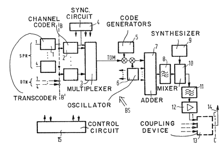
Figure 4 shows a block diagram of the sending part of the
base station BS. The data/speech signals transmitted in baseband are
composed as follows. The digitized speech in each channel is first
PHD 85337 11 10 . 07 .1986
recoded in a transcoder 1 from PCM to the transmission system required
for the transmission, with a correspondingly smaller bit rate. At the
intersection B-B a data source can be connected. In a channel coder 2
connected to the data source or transcoder 1 special channel coding is
added to protect significant bits against transmission errors in the
transmission channel. This channel coding may differ, depending on the
transmitting service. In a multiplexer 3 connected to the channel coder
2 the signalling accompanying the data flow is added, together with the
synchronization information from a sync circuit 4. The TDM signal
(Time Division Multiplex signal) at the output of the TDM
multiplexer 3 thus contains, in the embodiment illustrated in Eigure 4,
four speechtdata channels, one signalling channel accompanYing the
connection (for a TDM cluster of channels) and the synchronization bits
required for synchronization in the mobile stations MS. The
15 ~ n~ bits are merged with the TDM signal, as proposed in
The TDM signal at the output of multiplexer 3 is
multiplied by the codewords from the relevant code generators 5, whereby
two bits are combined to form one symbol and are spread with the desired
code. The spread signal is modulated by a method adapted to the
properties of the transmission channels, whereby for example the spread
signal is keyed so as to shift the phase of a carrier signal from an
oscillator 6, resulting in a signal carrying the information and the
codeword and which is modulated with a lower intermediate frequency
(Binary Phase Shift Keying, BPSK). The modulated CDM signal is fed to
an adder 7 whose output is connected to a bandpass filter 8. Eight of
these modulated CDM signals, after addition and bandpass filtering, form
a multistage-amplitude composite signal which is finally converted to
the end frequency.
For this purpose a mixer oscillator is provided as a
synthesizer 9, which can be switched in corresponding stages within the
frequency range of the digital radio transmission system. The
synthesizer 9 is designed only for the few possible frequencies of the
FDM stage (Frequency Division Multiplex stage). Mixing of the CDM
signals with the frequency delivered by the corresponding synthesizer 9
is performed in a circuit 10 which is connected to a bandpass filter
11. The output of the bandpass filter 11 is connected to a power
~a~228
PHD 85337 12 10.07.1986
amplifier 12, from which the filtered and amplified transmission signal
goes via a coupling device 13 to the antenna 14. In smaller base
stations BS with up to 32 message transmission channels the antenna
coupling device 13 is not required.
A control circuit 15 in the base station ~S takes care of
the setting of channel and code generators, the correct choice of
channel coding and the addition of announcements in the organization
data flow. The transmission channel selected~ for this purpose may be a
~: v. ~ ,4, 6
TDM channel in a CDM plane (see ~ 13~.J4-).
Figure 5 shows a block diagram of the receiving part of a
mobile station MS. The signal received from a common
transmitting/receiving antenna 16 passes through the reception filter of
a duplexer 17 to the input stage 18 of the receiver. The requirements
to be met by the reception filter of the duplexer 17 are not very
stringent, so that mobile stations MS with simple service functions,
e.g. simple data signalling, can be relatively inexpensive. In the
input stage 18 the signal is amplified and then mixed with a frequency
from the synthesizer 19 to form an intermediate-frequency signal.
The intermediate frequency signal is fed to an IF stage
20, where it is further amplified and filtered. As in the case of the
synthesizer 19 in the base station ~S, a simpler type can be used for
the synthesizer 9 in the mobile station MS, which can be produced more
cheaply. The IF stage 20 contains filters which serve to delimit
neighbouring channel selection against neighbouring broadband channels
and to suppress mixing products on it. The actual noise filtering takes
place in correlators 23, 24 and 25. Connected to the IF stage 20 is an
amplitude control circuit 21 which raises the output signal of the IF
stage 20 to a level sufficient to drive the subsequent stages and
prevents possible overloading of these circuits. The amplitude control
circuit 21 uses estimates to equalize variations in field strength and
level fluctuations, thus permitting linear processing of the signals in
the subsequent circuits of the mobile station MS. The control time-
constant of the amplitude control circuit 21 depends essentially on
these estimates.
The power-controlled IF signal at the output of the
amplitude control circuit 21 is converted into baseband in a demodulator
22 connected to 21. Using ~PSK modulation for example, this can be done
~Z8~2~3
PHD 85337 13 10.07.1986
in accordance with the Costas loop principle, which applies to both
frequency and phase. From the po~a~ity of the received synchronization
words it it possible (see ~ to recognize and equalize
ambiguities of integral multiples of 180.
Connected to the demodulator 22 are three correlators 23,
24 and 25 which, by means of a control device 26, can be set for the
applicable codes 1 and 2 and for a sync code applicable to the whole set
of channels in the transmission zone. The control device 26 also serves
for evaluating the organization data signals received, producing a read-
out of the data for the services required by users and the data for the
transmission channels provided for particular types of equipment, for
the selection of switchable transmission channels freely available to
the mobile station in the organization data flow, and an access signal
for transmission to the base station BS on this selected transmission
channel.
The output signal of the correlators 23, 24 and 25 is
used on the one hand for deriving the symbol, frame and bit
synchronization, and on the other hand for evaluating the instantaneous
multipath profile. Since a standard synchronization code of appropriate
level s sent out at the same instant in the combined group of channels
tsee ~ synchronization identification and evaluation of the
multipath profile are ensured.
The outpu~s of the correlators 23, 24 and 25 are
connected to scanning circuits 27, 28, which scan the output signals of
the correlators 23 to 25 and feed the result to a decision stage 29.
The results of the scans performed in the decision stage 29,
synchronously with the echoes of the multipath evaluations, are weighted
in proportion to the amplitude of the echoes (by a device 30). The
decision stage 29 has the task of estimating the transmitted code and
the polarity of the code. The estimated value makes it possible to
select the symbol that has most probably been transmitted. After the
symbol-bit conversion in the decision stage 29, the output signal is fed
to a TDM demultiplexer 31 connected to the decision stage 29. The
demultiplexer 31 is connected to a channel decoder 32 at the output of
which the transmitted data flow is again available. In digital speech
transmission the digital speech signal is decoded in a speech decoder
33, in a D/A converter and fed to a connected loudspeaker.
If a mobile station MS has been equipped for example for
2~8
PHD 85337 14 10.07.1986
a data service, the data appearing at the output of the channel decoder
32 can immediately be displayed or printed out.