Note: Descriptions are shown in the official language in which they were submitted.
~2~3~)3~:~
BACKGROUND OF THE INVENTION
In mod~rn surgical practice, ~any procedures which
formerly required large incisions have been supplanted
by techniques employing microsurgical tools. 5uch
tools are generally introduced to the surgical site
through small incisions which create far less surgical
trauma, and hasten healing and recovery.
A significant aspect of many of the newly developed
surgical tools is the use of vacuum aspiration to draw
tissue into a power driven cutting head. It is well
recognized that the rate of tissue cutting and removal
is related to the rate of operation of the cutting
head, and also to the vacuum level applied to the
aspiration port associated with the cutting head.
Thus it is clear that precise control of the vacuum
level is essential to success~ul operation of this
type of surgical instrument.
Until recently it was standard practice to have
tubing and hoses extending to the cutting instrument
to provide aspiration, irri~ation fluid, and motive
power to the cutting head. The tubing generally was
manually secured through pinch valves on the console
of a surgical instrument control machine to provide
control of the irriga~ion and aspiration functions.
However, this procedure was subject to human error in
the placement of the proper tubing in the proper pinch
3~
valve, and it was also possible for the tubing to
become dislodged accidentally. The outcome of such
errors can be catastrophic during surgery.
~` One means for overcoming this problem is disclosed
in United States Patent No. 4,475,904, issued October
9, 1984 to Carl C. T. Wang. This device provided a
pair of aspiration containers in a cassette housing,
one container having a significantly smaller volume
than the otherO The containers are connected by tubing
affixed to an outer wall of the cassette, and valves
extending from the console of the surgical control
machine are disposed to engage the tubing automati-
cally when the cassette is secured to the machine.
Also, the vacuum connections to the cassette are en-
gaged automatically upon installation of the cassette. `I
Thus the human error aspect is alleviated. More signi-
ficantly, the assembly provides the fast response to
changes in vacuum assoclated with a small volume while
also providing a large storage capacity.
However, pinch valves mounted on the exterior of a
machine exhibit intrinsic reliability problems, such
! as clogging by foreign matter, sticking, and the likaO Z
Furthermore, the tubing itself must be extremely resil-
ient to expand quickly when the pinch valves open, so
that the response time of the overall assembly does
not lag. If a tubing section remains pinched by a
valve for a long period of time, plastic deformation
may occur, and the flow channel will be constricted,
thus altering the operating characteristics of the
surgical tool. Temperature changes may also affect
the resilience of the tubing.
It is additionally problematic that many times
surgery requires contemporary use of different types
of surgical instruments. As previously discussed~
aspiration, irrigation, and mode of power for a
.1 .
., .
1, ~
.,
', .
1,
3;~6
-4-
~'
cutting tool require connection to different sources.
Use of tubing or hoses is susceptible to problems, as
previously discussed, which is compounded by the dif-
ferent sources and types of tools. It would thereEore
be advantageous to have an integrated control center
and conduit for the dif~erent sources and tools.
SUMMARY OF THE PRE~SENT_INVENTION
., .
The present invention generally comprises a vacuum
aspiration collection system which features all of the
conveniences and error-free aspects of a cassette
system, while alleviating the problems associated with
tubing and pinch valve operation. Thus the invention
provides fast response to changes in demand for vacuum
at the aspiration port, large capacity for storage of
aspirated ~luids and tissue, and highly reliable setup
and operation.
In a first preferred embodiment of the invention,
the fast response, tubeless vacuum aspiration collec-
tion casse-tte includes large and small containers
defined within a cassette housing adapted to be removably
, secured to a surgical aspiration machine. A first
i wall assembly of the cassette housing abutting the
~achine includes connectors positioned to engage ports
in the machine to provide a controlled variable vacuum
level to the small container, and a fixed vacuum level
to the large container. Valves formed in the first
wall are interconnected by flow channels therein ex-
tendiny to the containers, each valve having an actua-
ting s~em extending from the wall and positioned to be
actuated selectively by appropriate components of ~he
machine.
A second wall of the cassette housing opposed to
the first wall includes a tubing connector extending
,
.,
.
., ,
.
"
,,
--5--
to a surgical probe or cutting instrument. The chann01s
and valves are arranged so that when the containers
are isolated by a first valve, the controll0d vacuum
level may be applied to the surgical probe through a
second valve connectin~ the probe to the small con-
tainer volume. Whenever the controlled vacuum i5 shut
off to the probe by the second valve, the first valve
is opened to permit the fixed vacuum in the larger
con-tainer to be applied to the smaller container to
transfer aspirant fluid therein to the larger container
by vacuum induction. In addition, a liquid level
sensor in the ~small container is connected to trigger
emptying of the small container whenever a preset
liquid level is reached. Thus the smaller container
is not per~itted to fill completely, and the small
volume thereof provides a minimal time lag in deliver-
ing the desired vacuum level to the surgical instrument
or probe.
Each of the valves comprises a generally cylin~
drical valve chamber formed in the first wall assembly,
with one flow port extending generally axially into
the chamber and the other spaced laterally therefrom.
An elastic membrane is clamped under tension across
the valve chamber, extending generally perpendicularl~
to the axis of the chamber. A piston is received in
the cylindrical chamber and disposed to impinge on the
outer surface of the membrane, with a plunger exten-
ding from the piston outwardly of the wall assembly.
Depression of the plunger drives the membrane to im-
pinge upon the axially disposed port, thus interrup-
ting the flow path between the two ports. The elastic
nature of the membrane acts to bias the piston to the
normally open position in which the flow path is main-
tained.
In a second preferred embodiment of the invention,
., ,
3~g; ;
--6--
the fast response, tubeless vacuum aspiration collec-
tion cassette includes one fluid collection container.
I Communication with a controlled variable vacuum source
in the surgical aspiration machine and the conduit
extending to the surgical probe or cutting instrument
are sub~tantially similar to those discussed with re-
gard to the first preferred embodiment. A first wall ,
portion of the casset-te housing abutting the machine
includes a connector positioned to engage a port in
the machine to provide a controlled variable vacuum
level to the container through a flow channel. A
second flow channel extends to a port which is in
~ communication with the connector adapted to be con-
`1 nected to a tubular conduit extending to a surgicalprobe or cutting instrument. A valve formed in the
first wall portion is interposed in the second flow
channel and has an actuating stem extending from the
wall and positioned to be actuated selectively by
,1 appropriate components of the machine.
,1 An additional feature of the second preferred
,~ embodiment includes input and output ports for attach-
ment to a fluid infusion source and fluid infusion
tool respectively. The input and output ports are i
formed within the first wall portion and are inter-
,1 connected by a flow channel substantially the same as
the other flow channels. Another valve is interposed
in the flow channel and allows selective flow of in-
fusion fluid between the fluid infusion source and
tool.
The valves of the second preferred embodiment are
substantially similar to those described with respect
to the first preferred embodiment of the invention,
and operate in conjunction with an elastic membrane
clamped under tension across the valve chambers.
, i
., .
3~;
-7-
I BRIEF DESCRIPTION OF THE DRAWING
Figure 1 is a perspective view of the asp.iration
cassette assembly of a first preerred embodiment of
the present invention.
Figure 2 is a rear view of the aspiration cassette
assembly depicted in Figure 1.
Figure 3 is a side view of the aspiration cassette
assembly depicted in Figures 1 and 2.
Figure 4 is a plan view of the rear panel layout
of the aspiration cassette assembly of Figure 1.
Figure 5 is a cross-sectional elevation of the
rear panel assembly, taken along line 5-5 of Figure 4.
Figure 6 is a cross-sectional elevation of the
rear panel assembly, taken along line 6-6 of Figure 4
Figure 7 is a cross-sectional elevation of the
;j i
rear panel assembly, taken along line 7-7 of Figure 4.
Figure 8 is a cross-sectional elevation of the
rear panel assembly of the cassette assembly, taken
along line 8-8 of Figure 4.
Figure 9 is a partial cross-sectional elevation of
the rear panel assembly of the cassette assembly,
taken along line 9-9 of Figure 4.
Figure 10 is a cross-sectional view of the cassette
assembly, taken along line 10-10 of Figure 8~
Figure 11 is a plan view of the valve stem and
piston assembly of the present invention. -
Figure 12 is a partially cross-sectioned detail
view of the corner assembly of the present invention~
Figure 13 is an enlarged, cross-sectional view of
the valve assembly according to the present invention
of Figure 1.
Figure 14 is a partial plan view of the rear wall
of the aspiration cassette of Figure 1.
Figure 15 is a cross-sectional elevation taken
along line 15-15 of Figure 14.
.1 ,
., ,
.
. l
, i.
3~
--8--
Figure 16 is a cross-sectional elevation taken
along line 16-16 of Figu~e 14.
Figure 17 is an enlarged, detailed cross-sectional
view taken along line 17-17 of Figure 4.
Figure 18 is a detailed plan view of the valve
construction of the present invention of Figure 1.
Figure 19 is a perspective view of a second pre-
ferred embodiment oE the present invention.
Figure 20 is a cross-sectional elevation taken
along lines 20-20 of Figure 21.
Figure 21 is a side cross-sectional elevation
taken along line 21-21 of Figure 19.
Figure 22 is a top cross-sectional view taken
alGng line 22-22 of Figure 20.
Figure 23 is a top cross-sectional view taken
along line 23-23 of Figure 20.
Figure 24 is an enlarged, cross-sectional view of
the vent assembly according to the present invention
of Figure 19, showing venting in operation.
Figure 25 is a schematic representation of an optional
auxiliary fluid container system which can be used
with the present invention.
. ' .
DESCRIPTION OF THE PREFERRED EMBODIMENT
The present invention generally comprises a device
for collecting aspirant fluid from a vacuum aspiration
surgical ins~rument or probe. It can optionally also
control delivery of in~usion fluid to an infusion
surgical instrument or probe. One salient feature of
the inVQntion is that the device includes a cassette
configuration which releasably engages the surgical
instrument operating machine by simple plug insertion,
thereby making all the re~uired connections with the
machine. Also, the cassette includes therein all the
.
,, ,
.1.
;
, ~ ,
~8~:~3Z~
_9_
valves necessary to control the vacuum aspiration or
infusion fluid functions, thus obviating the prior art
problems associated with tubing connections, pinch
valves, and the like. Moreover, the invention exhi~
bits extremely fast response time in shifting the
vacuum induction level, while also providing a large
storage capacity for aspirant fluid and tissue debris.
Other features of the invention will be apparent in
the following description.
A first preferred embodiment of the invention i5
shown in Figures l-18, and will be described as follows.
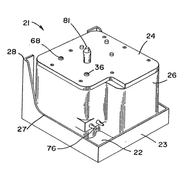
With regard to Figures 1-3, the cassette 21 o the
present invention includes an outer end wall 22 which
is generally rectangular in configuration, with a
narrow frame 23 e~tending about the periphery of the
wall 22. An inner end wall 24 is parallel and spaced
apart from the wall 22, and is provided with a smaller
proEile, slightly irregular rectangular configuration.
A sidewall 26 extends continuously between the two end
walls to define an enclosed volume therewith~ The
sidewall and end walls are preferably formed of molded
polymer material, and are joined by adhesive means or
ultrasonic welding to form a sealed unit. At the
lower portion of the cassette, the rame 23 includes a
portion 28 which flares to extend from the outer end
wall to the inner end wall, adjacent to the opposed
corners of the lower edge 27 of the wall 22.
With regard to Figures 4r 8~ and 10, the cassette
21 is provided with interior walls which define, to-
gether with the outer sidewalls 26, a pair of sealed
containers 30 and 31. It is significant that the
con-tainer 30 is s~all in volume, and that the container
31 is substantially larger. A system of flow channels
i and valves, formed by an assembly with the end wall
24, selectively connected the two containers. In
"
', ~
"
,
~i Z80~
-10-
addition, the smaller container 30 is connected to a
controlled, variable vacuum source, and this source of
vacuum is connected through the smaller container 30
to a surgical instrument or probe to aspirate fluid
and tissue therefrom into the sma:Ller container. It
may be appreciated that the small volume of the con-
tainer 30 closely follows the vacuum level of the
source connected to it, so that the vacuum aspiration
demanded by the surgeon is delivered to the surgical
tool with virtually no perceptible time lag. Also,
the system connects the larger container 31 to a fixed
vacuum source and selectively to the smaller container,
so that the smaller container may be emptied whenever
it becomes full, or whenever the operation of the
surgical instrument is halted even momentarily.
Joined to the end wall 24 is an inner panel 32
disposed parallel thereto and having the same general
outer proile. A gasket member 33 is also provided
with the same general outer profile, and is secured
compressively between the wall 24 and the panel 32.
The gasket 33 is formed of a resilient, inert mater-
ial, such as silicone rubber or the like. A plurality
of locating pins 34 extend from the inner panel 32
through appropriately placed holes in the gasket to be
received in friction fit in apertures in the end wall
24. The pins 34 facilitate assembly of the device in
a precision manner, and the gasket provides a pres-
sure-tight vacuum seal. In addition, the inner panel
32 includes flow channels and valve chambers formed
integrally therein during the molding process, so that
the end wall 24 together with the inner panel and the
gasket de~ine all the required valves and flow channels.
Extending distally from the end wall 24 is a vacuum
connector nipple 36, as shown in Figure 8. The nipple
l 36 is disposed to be engaged by the surgical instrument
.. 1.
~ ~ ,
. i
ll l
.
`
3~6
control machine, and a passage 37 leads therefrom
through the end wall 24 to a filter well 38. A hydro-
phobic filter membrane 85 is received in the well 38,
and is clamped at its outer edge be-tween the end wall
24 and the gasket 33. From the Eilter well 3B a pas-
sage 39 in the inner panel 32 leads directly to the
sealed volume of the small container 30. The connec-
tor 36 receives the controlled, variable vacuum from
the surgical machine, and transfers this vacuum directly
to the small container 30.
A port 41 in the lower end of the container 30
extends to a flow channel 42 formed in the panel 32,
as shown in Figures 4 and 8. The flow channel 42
extends obliquely to the vicinity of a valve chamber
43, which comprises a cylindrical cavity Eormed in the
inner panel 32. The channel 42 extends about the
periphery of the valve chamber 43 ~or more than half
the circumference thereof, and joins a recessed flow
passage 44, as also shown in Figure 6. The passage 44
leads to a port 46 extending axially into the valve
chamber 43. A flow channel 47 extends in the inner
panel 32 to join the valve chamber 43 and the cylin-
drical chamber 56 in a tangential relationship, as
also shown in Figures 4 and 9.
A valve stem actuator 51 extends outwardly through
a hole in the end wall 24, and is joined at the inner
end of a piston head 52, as also shown in Figures 6
and 11. The inner end of the piston head has a cham-
fered portion 53 to present a smoothly contoured sur-
face to inpinge upon the gasket 33- The head 52 is
smaller in diameter than the valve chamber, and the
stem 51 is aligned axially therewith. It may be appre-
ciated that inward translation of the stem 51 drives
the head 52 to deform the gasket 33 elastically, urging
the gasket material to block the port 46 and prevent
- .
2~
-12-
fluid flow through the valve chamber. See also Figure
13. The elastic nature of the gasket material opposes
the inward transla~ion of the valve stem, and assures
~I that the valve will be biased to the normally open
position to restore fluid flow when the valve stem is
released. The valve stem is actuated by a mechanism
of the surgical instrument operating machine, which
forms no part of the present invention.
The flow channel 47 leads to a cylindrical chamber
56 similar in configuration to the valve chamber 43~
Another flow channel 57 extends from the chamber 56,
and leads to a delivery tube 58 which extends to the
outer end wall 22 tFigure 8). A tubing nipple 59 may
be mounted on the outer end of the delivery tube 58 to
connect to the aspiration tube of a surgical instru-
ment or probe. The flow channels 47 and 57 enter the
chamber 56 in diametrically opposed relationship.
A valve stem 51 extends through the end wall 24,
and functions as its counterpart 51 to deform the
gasket portion upon which it impinges and urge that
portion into the chamber 56, as shown in Figure 9.
i However, the gasket portion in the chamber 56 does not
block the fluid flow therethrough, due to the diametri-
cal relationship of the flow channels entering therein.
Rather, the piston 52 is provided to create a back pres-
sure wave, or reflux, whenever the vacuum delivered to
the surgical instrument is shut off by the valve 43.
To summarize the function o the components described
thus far, the controlled variable vacuum provided to
the small container 30 by the connector 36 is delivered
through the channel 42, valve 43, chamber 56, channsl
57, and delivery tube 58 to the aspirating surgical
instrument. When the surgeon desires to cease the
cutting action of the instrument, a hand or foot con-
trol is actuated to activate the valve stem 51 and
~,
.,
., .
,,
., '
2~
j -13-
close the valve 43. Thus any ur-ther vacuum induction
of tissue into the surgical instrument is stopped
abruptly. However~ a vacuum condition may remain in
the fluid channel extending from the valve 43 to the
surgical instrument. This residual vacuum may act to
retain tissue in the cutting instrument; when the
surgeon withdraws the instrument from the surgical
site, the tissue may be torn or damaged. This ef-fect
can be especially serious in delicate eye surgery and
the like.
Thus, the reflux action of the chamber 56 is an
important feature of the present invention in preven-
ting such acciden-tal damage. Whenever the valve 43 is
closed to stop the vacuum aspiration, the valve stem
51 is actuated to drive the gasket 33 into the chamber
56, thereby displacing a small amount of the fluid in
the chamber into the fluid flow path from the surgical
instrument to the valve 43. The result is that the
residual vacuum is alleviated, and any tissue retained
in the cutting instrument is released.
The distal end of the arcuate portion of the flow
channel 43 is also connected through a short channel
portion 61 to a valve chamber 62. The valve chamber
62 is configured similarly to the chamber 43, and a
valve stem actuator 51 is translatably secured in the
end wall 24 and disposed to function like its counter-
part 51 described previously. The axially disposed
port 63 of the chamber 62 connects to a recessed flow
channel 64, and thence to a flow channel 66, as shown
in Figure 4 and 5. The flow channel 66 terminates in
a port 67 which opens into the large container 31.
Thus a fluid flow path from the small container to the
large container is defined through channels 42 and 61,
valve chamber 62, channels 64 and 66, and port 67,
with the valve 62 being interposed to selectively
I
. ~ ~
il i.
. ~ I
,
~21~0~326
-14-
block the flow path.
Also extending outwardly from the end wall 24 ls
another vacuum connector nipp]e 68. Like khe connec~
tor 36, the connector 68 is positioned to be connected
with a port in the surgical tnachine, and is provided
; with a generally constant vacuum by the machine. The
connector 68 is joined by a passage 69 to a filter
well 71 which is also covered by a hydrophobic mem-
brane 85, and thence through a flow channel 72 to a
I port 73 in the large container 31 (Figures 4 and 7).
Thus the constant vacuum applied to the connector 68
is delivered directly to the large container 31. It
should be noted that the container 31 includes a sep-
tum wall 74 which separates the vacuum port 73 and the
fluid intake port 67, so that no fluid inadvertently
enters the port 73. Also, the hydrophobic membrane
permits gas flow into the surgical machine, but pre-
vents aspiration of any liquid into the surgical machine.
To summarize the operation of the cassette of the
first preferred embodiment of the present invention,
the controlled, varible vacuum level of the surgical
machine is applied to the connector 36 and conducted
directly to the small volume of the container 30. To
provide vacuum aspiration to a surgical instrument
connected to the nipple 59, the valve 43 is open to
permit vacuum connection from the small container
through flow channel 42, valve 43, channels 47 and 57
to the delivery tube connected to the instrument. At
the same time the valve 62 is closed, thus isolating
the large and small containers.
Whenever the surgeon desires to curtail the vacuum
aspiration effect, even momentarily, the surgeon's
controller activates the machine to close valve 43,
thus interrupting the aspiration flow path to the
surgical instrument. At the same time, the valve stem
',
,1 1
,, 1,
~., 1
-15-
51 is actuat0d to displace fluid in the aspiration
channel and alleviate the residual vacuum therein to
release any tissue en~rained in the surgical cutting
instrument. Also at the same time, the valve 62 is
opened, thus connecting the two containers through the
channels 42 and 47r the valve 62~ and the channel 66
The vacuum level constantly applied to the connector
68 causes any fluid above the port Al of the small
container to be drawn rapidly into the large container
through the open flow channel just described/ thus
emptying the small container.
The small container also includes a pair of elec-
trodes 76 which extend into the upper portion of the
small container and are connected to a circuit in the
surgical machine which senses fluid immersing the two
electrodes. Whenever fluid bridges the two electrodes
76, the machine temporarily disables the surgical
instrument, closes valve 43, actuates the reflux de-
vice 56~ and opens the valve 62 to drain the small
container. This process requires a very brief time to
complete, and assures that the small container will
not fill to the level of the port 39, thus preventing
fluid aspiration into the surgical machine.
With regard to Figure 17r it should be noted that
all of the flow channel and valve chamber features
described herein include a raised lip 79 extending
continuously from the inner panel 32 and impinging on
the gasket 33. The lip assures a vacuum-tight seal
with the gasket, and is integrally molded with the
panel 32.
The cassette 21 also includes a pilot pin 31 ex-
tending outwardly from the end wall 24, as shown in
Figures 1-3 and 15-16. Th pilot pin is disposed to be
received by a complementary part of the surgical mach-
iney and is provided to guide and secure the engagement
,
.
,,
,, I
,.
.. ~
~'~803~
-16-
of the connectors 36 and 68 with the machine. The pin
81 includes a detent slot 82 spaced proximally froln
the end thereof and adapted to be engaged by a latch
mechanism of the surgical machine to secure the cas
sette to the machine in the operative position.
The cassette of the present invention is easily
Eormed by plastic molding techniques, and may be manu-
factured inexpensively. Thus the cassette is suitable
for single usage, and disposal thereafter. A plugged
port 84 extending through outer wall 22 to the large
container 31 is provided so that the aspirant fluid
and tissue debris may be withdrawn for pathology analy-
sis and the like.
Although the tubeless vacuum aspiration collection
cassette of the present invention has been described
above in connection with a preferred embodiment in
which a pair of containers is utilized, it will be
appreciated by those skilled in the art that the flow
passage means, valve means, valve actuator means, and
other important features of the present invention are
adaptable for use in cassettes which utilize either a
single container or ~ore than two containers.
It is also to be appreciated by those skilled in
the art that the flow passage means, valve means,
valve actuator means, and other important features of
the present invention are adaptable for use in cassettes
for the selective control of fluids, in addition to -
air under vacuum, which are used in surgical proce-
dures. Such examples include, but are not limited to,
infusion fluid and pressurized air.
A second preferred embodiment of the present inven-
tion is therefore shown in Figures 19-24, and described
as follows.
With particular reference to Figures 19-21, the 1i
second preferred embodiment of the present invention
. I
, . ,
.j I
.' ;
, 1 .
~28~3;;~;
~ -17-
~` ~
comprises a cassette 100 substantially similar in
design and operation to cassette 21 of Figures 1-18.
I A pilot pin 102 (see Figures 22 and 23), like pilot
pin 81 oE the first preferred embodiment, locks cassette
100 to the surgical rnachine.
Cassette 100, like cassette 21, can be connected
to tubing conduit extending to a surgical aspiration
tool, and is also connectable to an aspiration source
in the surgical machine. Flow passage means, valve
means, and valve actuator means, substantially the
same as with regard to the first preferred embodiment,
allow control of direction of aspiration to the aspir- ;
ation tool the control and direction of aspiration
fluid and depris to a collection container 10~ disposed
within cassette 100.
Cassette 100 also includes the additional optional
feature of allowing selective control of infusion
fluid between an infusion fluid source and conduit
tubing to an infusion fluid surgical tool. Cassette
100 includes an infusion fluid lnlet 104 and an in-
fusion fluid outlet 106 connectible to an infusion
fluid source and tool respectivelyO Flow passage
means, valve means, valve actuator means, substantially
~ similar to those shown in and described with regard to
i the first preferred embodiment of the present inven-
l tion, are utilized to control infusion fluid to the
!, infusion fluid surgical tool.
It is to be understocd that the elements and oper-
ation of cassette 100 function substantially in the
same way as described with regard to the first pre
ferred embodiment of the present invention, and there-
fore reference should be had to that description and
1 will not be repeated herein.
ill The primary differences between cassette 100 and
cassette 21 are summarized as follows. As shown in
,
. ' .
,1 1
.i
, 1,
. I ,
~30~2~
--18--
Figure 20, a single fluid collection container 108 is
disposed within cassette housing 110. A Eirst wall
portion 112 of cassette housing 110 extends above
container 108. As is most clearly shown in Pigure 20,
a plurality of fluid flow channels are formed in the
machine-facing surface 114 of wall portion 112. A
first Elow channel 116 connects circular filter well
118 to a port 120. Port 120 i5 in turn in communication
with bore 122 which is in turn is in communication
with the interior of container 108. As shown in Figure
21, a connecting nipple 124 is in fluid communication
with circular filter well 118 containing a hydrophobic
filter membrane 1260 Nipple 124 automatically connects
to the aspiration source of the machine when cassette
100 is connected and secured to the machine. First
flow channel 116, port 120, and bore 122, in con;unction
with filter well 118 and port 128 associated with
connecting nipple 124 therefore supply asI?irating
vacuum to container 108.
A second flow channel 130 in first wall portion
112 extends between segmented well 132 and valve cham-
ber 134 which surrounds port 136. Port 136 in turn is
in fluid communication with bore 138 which fluidly
communicates with container 108. Segmented well 132
is in fluid communication with port 14û which is asso-
ciated with aspiration tool nipple 142. The 1uid
pathway through segmen ted well 132, second 10w channel
130, and bore 133 provides a pathway for fluid and
debris aspirated rom the surg ical aspiration tool
into the collection container 108. Valve chamber 134
cooperates with gasket member 172 and valve stem 176,
in the same way as previously described with regard to
the first preferred embodiment, to allow closing and
opening of this fluid pathwayO
. A third flow channel 148 and fourth flow channel
!
~, .
.
, I
f f
3L~8(~3Z~;
-19-
150 are formed in first wall portion 112J Third flow
channel 148 at one end communica-tes with port 152
which in turn communicates with infusion fluid ;nput
nipple 154. The o~her end of third flow channel l48
~ communicates with recessed Elow channel 156 which in
turn communicates with port 158 in the center of valve
. chamber 160. Fourth flow channel 150 communicates at
one end with port 162 which in turn communicates with
infusion fluid outlet nipple 164. The other end of
fourth flow channel 150 communicates directly with
valve chamber 160. Valve chamber 160, like valve
chamber 134 and those described with regard to the
I first preferred embodiment o the invention cooperate
.` with gasket 172 and valve stem 176 to selectivel~
block port 15~ and stop fluid flow between third and
fourth flow channels 148 and 150- Thus, the surgical
machine can also control infusion fluid to an infusion
fluid tool.
~spiration tool nipple 142, infusion fluid input
nipple 154, and infusion fluid outlet nipple 164 ex-
tend from the surface 168 of wall portion 112 which '.
l faces away from the surgical machine. They extendthrough appropriate aperatures in a manifold hood 170
which extends up and overfirst wall portion 112.
Hoses or tubing conduit, as appropriate are connected
to the nipples as desired. Figures 21-23 show how
gasket membrane 172 is sandwiched over the flow chan-
I nels wells, and valve chambers in first wall portion
. 112 by a backplate 174. Backplate 174 can be securedto first wall portion 112 similarly to that described
.. with regard to the first preferred embodiment of the
I invention.
l It is also to be understood that the second pre-
ferred embodiment includes a vent and check valve to
vent the aspiration line to the surgical aspiration
.
.~ I
I' ~
, I ,
-20-
tool to atmosphere. By referring to Figures 20, 23,
and 24, the check valve and vent can be described. A
vent nipple 144 surrounds a port 140 and extends out-
wardly from back plate 174. Vent nipple 144 connects
with a venting valve in the machine when cass~tte 100
~ is secured in the machine. The venting valve i5 con-
I nected to atmosphere, is controlled by the machine,
and operates as is known in the art.
Port 140 has a raised lip 178 surrounding it,
which in turn is surrounded by a well 180. As can be
seen in Figures 23 and 24, port 140, lip 178, and well
180 align with segmented well 132 in first wall por-
tion 112, but are separated from it by gasket 172.
Although small apertures 146 exist in gasket 172~
fluid and debris traveling through aspiration nipple
142 into second flow channel 130, and on to container
108, can not enter vent nipple 144 because when the
venting valve in the machine is closed, gasket 172, in
its normal state, covers and seals over raised lip 178
around port 140. The positioning of the four small
apertures 146 can be seen in Figure 20. It is also
pointed out that spoke members 182, which extend from
first wall portion 112 into segmented well 132, keep
gasket 172 from blocking the flow path through aspira-
tion 142.
j Figure 24 shows that when aspiration is stopped
to the aspiration tool, and the venting valve in the
machine is opened, the atmospheric pressure causes
gasket 172 to move away from lip 178 and the aspira-
tion line is vented to atmosphere through small aper-
tures 146. This assists in diminishing residual vacuum
in the aspiration line.
Figure 25 shows an additional modification which
can be made to the cassettes of the invention to pro-
vide auxilliary storge of fluid or debris aspirated
, fl
,. I
. i
,. i
,1 ~
. ~
,
~8(~32Çi
-21-
into the collection container, such as container 3l of
the first described preferred embodiment, or container
108 of the second described preferred embocliment.
Figure 25 shows a cassette 200 in accordance with the
present invention with a Eluid container 202 disposecl
therein. An aperture 204 is in fluid communication
with the interior of container 202. It is preferred
that aperture 204 be at least 1/2" below t:he top of
container 202. A plug 206 is sealingly positioned in
aperture 204, but also has an aperture 208 into which
a tube 210 is sealingly mounted. The opposite end of
tube 210 is connected in fluid communication with
sealed auxillary bag 212. A check valve 214 is interposed
along tube ~lOo Check valve 214 allows fluid and
debris to drain from container 202 to bag 212 when the
level of fluid and debris in container 202 reaches
aperture 208 in plug 206. Such drainage is by gravity.
Check valve 214 disallows, however, passage oE fluid,
debris, or air from bag 212 back to container 202 when
container 202 is under vacuum.
Such check valves are well-known to those of ordi-
nary skill in the art and can take on various configur-
ations while accomplishing the objects above described.
An example is a diaphram check valve which allows fluid
flow in one direction, but disallows it in another.
A further example is a duckbill check valve. Other
types could be used as is known in the art.
The auxiliary storage system described above is
particularly useful in phaco-emulsification ophthalmic
procedures, but is applicable to most, if not all,
ophthalmic procedures.
~. I
,. I
,
1, 1
, ~ ,
~032~
; -22-
It will be appreciated that the present invention
can take many forms and embodiments. The tru~ essence
and spirit o~ this invention are defined in the appended
claims, and it is not intended that the embodiments o
the invention presented herein should limit the scope
-thereof.
~ `
.j
, ,
., ,
I
~ !
' i
`i ,.
,. ~.
ll
,
., ,
;; I