Note: Descriptions are shown in the official language in which they were submitted.
~8~
-1- 72290-13
I. Field of the Invention
This invention relates to a one-trip packstock assembly
and, in particular, to a whipstock packer assembly having a small-
er than usual outer diameter yet capable of effectively packing-
off conventional casing diametersO
II. Description_of the Prior Art
Well packers are widely utilized to seal or isolate
one or more zones in a well hole. Generally, several levels of
interest are sealed from each other by a packing arrangement
between the well casing and the work string. Packers have also
been utilized to orient and support additional tools, such as a
whipstock, in order to control the direction of the tool. How-
ever, most of the past known packing tools are generally designed
to pack-off and seal gaps of 3/16" or smaller. Thus, the initial
diameter of the packing device must closely conform to the inner
dimensions of the well casing.
Because of the small leeway provided in conventional
packing tools, such devices have a tendency to hang-up in the
casing as they are lowered therein. This is particularly pro-
blematic in casing packers which are run in conjunction withadditional tools thereky extending the overall length of the
combination tool. As the length of the tool associated with the
packer is increased, the ability to maneuver through irregular
casing sections is decreased due to the limited leeway between
~ .
~6:~362
-2- 72290-13
the packer and the casing wall. In order to reduce hang-ups,
such multiple tool operations are generally conducted in two
trips. The first trip is utilized to run and set the packiny
device while the second trip positions the working tool, such as
a whipstock utilized to sidetrack a well. Since the packing tool
was only a few feet long it could easily be maneuvered through
the casing. However, the two trip operations resulted in in-
creased costs particularly in very deep well operations. More-
over~ while running the whipstock and packer individually is
normally a fairly simple procedure, a highly deviated well may
require that the packer be run on the drillstring. In this
situation, a simple procedure becomes time-consuming and complex.
In order to reduce production costs, a one-trip tool
adapted to pack-off gaps of greater than one-half inch was
developed. Such a combination tool is described in U.S. Patent
No. 4,397,355 entitled WHIPSTOCK SETTING METHOD ~ND APPARATUS.
The packing tool descri~ed therein is adapted to pack-off the
increased gap. However, it has been found that because of the
larger gap the rubber sealing element has a greater tendency to
extrude along both the inner mandrel and the casing wall, thereby
causing leakage past the packing element. Pressure packers have
also been utilized in an attempt to prevent this leakage. How-
ever, these pressure packers would only withstand pressures
proportional to the pressure initially put into packers since the
pressure supply line is severed upon actuation of the whipstock.
~2~ i2
_3_ 72290-13
Any increase in downhole pressure would cause leakage past the
tool.
Thus, the past known tools have failed to effectively
seal and pack-off the casing, particularly whan eY~treme well
pressures are present.
According to one aspect of the invention, there is
provided a packing assembly for sealing between an inner mandrel
and a well casing, the assembly having expandable slip-type anchor-
ing means mounted to the mandrel, a plurality of sleeves slidably
mounted coaxially on the mandrel and means for setting the
anchoring means, the improvement comprising packing means to
sealingly engage the well casing and the inner mandrel, the pack-
ing means including at least two resiliently deformable packing
elements and means for variably deforming the packing elements in
response to fluid pressure in the well casing; and means for
compressing the packing means into sealing engagement with the
well casing while preventing extrusion of the packing elements.
According to another aspect of the invention there is
provided an apparatus for setting a whipstock and for changing
the direction of drilling through a casing wall with a single
trip of tha drill string, the apparatus comprising:
a whipstock;
a well string;
a mill connected on the drill string;
' ,.
3~2
-~a 72290-13
means releasably connecting the mill to the upper
portion o~ the whipstock;
a packing assembly;
means connecting the packing assembly to the lower end
of the whipstock; and
a fluid passage extending through the well string, the
mill, and the whipstock to the packing assembly;
the latter having
expandable slip-type anchoring means with means for
setting the anchoring means;
packing means to sealingly engage the casing wall
including at least two resiliently deformable packing
elements and means for variably deforming the packing
elements in response to fluid pressure in the well
casing; and
means for compressing the packing means into sealing
engagement with the casing wall while preventing
extrusion of the packing elements.
According to a third aspect of the invention, there is
provided an apparatus for setting a whipstock and for changing the
direction of drilling through a bore wall with a single trip of
the drill string, the apparatus comprising
a whipstock detachably connected to the drill string;
a packing assembly;
- :,
,.: : . -
33~2
-3b- 72290-13
means connecting the packing assembly to the lower
end of the whipstock; and
a fluid passage means extending through the whip.stock
to the packing assembly;
the packing assembly being responsive to 1uid pressure
supplied through the passage means.
Brief Description of the Drawings
The present invention will be more fully understood
by reference to the following detailed description of a preferred
embodiment of the present invention when read in conjunction with
the accompanying drawings, in which like reference characters
refer to like parts throughout the views, and in which:
Figure 1 is a cross sectional perspective of a well
bore with the apparatus of the present invention oriented therein;
Figure 2 is a cross-sectional perspective of a well
bore with the apparatus oriented therein and the packing assembly
set.
Figure 3 is a cross-sectional perspective of a well
bore with the apparatus oriented therein and the mill separated
from its attachment to the whipstock apparatus;
Figure 4 is a partial sectional perspective of the
packer assembly of the present invention in the unset or running
position;
Figure 5 is a partial sectional perspective of the
packer assembly set within a well bore;
~8C~1362
_4_ 72290-13
Figure 6 is an exploded perspective o~ the components
of the packer assembly;
Figure 7 is a partial cross-sectional view of the
packing means of the present invention in its unset position;
~ igure 8 is a partial cross-sectional view of the
packing means in the set or compressed position;
Figure 9 is a partial cross-sectional view of an
alternative embodiment of the packing means of the present
invention; and
Figure 10 is a partial cross-sectional view of a
still further embodiment of the packing means of the present
invention.
Detailed Description of a Preferred
Embodiment of the Present Invention
Referring first to Figures 1 through 3, the whipstock
assembly is thereshown oriented within the well bore or casing
12 by drill string 14. The whipstock assembly 10 generally
includes a packing assembly 16 which is connected by sub 18 to the
lower end of whipstock 20. A mill 22 is releasably connected to
~o the whipstock 20 by shear pin 24 so that the entire assembly 10
can be run into the casing at one time. The whipstock assembly
10 is lowered into the well bore 12 by way of drill string 1
until the desired orientation is achieved in the area of the
directional cut through the bore wall as will be subse~uently
described. Depending upon the desired operation, the whipstock
20 and the packing assembly 16 can first be run into the hole
using a setting toûl or other type of running device or,
336~:
-5- 72290-13
alternatively, the whipstock assembly 10 can be run in con-
junction with the detachable mill 22 in order to further reduce
the number of operations.
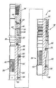
Referring now to Figure 4, the packing assembly 16
includes an inner mandrel 30, a piston rod 32 threadably connect-
ed to the upper end of the mandrel 30, and an adapter sub 34
threadably connected to the upper end of the piston rod 32. The
packing assembly 16 also includes an upper, slip-type anchoring
means 38 mounted to the mandrel 30 above packing means 42 and a
lower, slip-type anchoring means 39 mounted to the mandrel 30
below packing means 42. Both anchoring means 38 and 3~ include
a plurality of expandable slips 40 which move outwardly to engage
the well casing thereby setting the tool as will be described.
Lower anchoring means 39, packing means 42 and upper
anchoring means 38 are sequentially set through hydraulic pre-
ssure supplied from the work string 14 through a supply line 26
which is connected to a central passage 44 formed in the adapter
sub 34. The passage 44 is connected to annulus 46 by way of one
or more lateral ports 48. The annulus 46 acts as a cylinder
chamber such that as hydraulic pressure within the annulus 46
increases, piston 50 and piston sleeve 52 are caused to move
downwardly relative to the piston rod 32 and outer retaining
sleeve 53. In order to prevent pressure loss, the piston 50 is
provided with a plurality of O-ring seals 54 along the inner and
outer surfaces thereof. Downward movement of the piston assembly
-6- 72290-13
in turn acts against a lock housing 56 mounted to the mandrel 30.
The lock housing 56 cooperates with a lock nut 58 which interacts
with the inner mandrel 30 to prevent release of the packing
assembly 16 when pressure is released after setting of the tool.
The inner radial surface of the lock housing 56 includes a
plurality of serrations which cooperate with the inversely
serrated outer surface of locking nut 58. Similarly, the outer
radial surface of mandrel 30 includes serrations which cooperate
with inverse serrations formed in the inner surface of locking
nut 58. Thus, as the piston assembly causes the lock housing
56 to move downwardly, the locking nut 58 moves in conjunction
therewith causing the inner serrations of the locking nut 58 to
move over the serrations of the mandrel 30. The interacting
edges of the serrations ensure that movement will only be in one
direction thereby preventing release of the anchoring and pack-
ing means.
Referring still to Figure 4, the lock housing 56 is
connected to an inner sleeve 60 by shear screws 62. The inner
sleeve 60 extends beneath the slips 40 of upper anchoring means
38 and abuts against upper cone 64. The upper cone 64 is
releasably connected to the inner mandrel 30 by shear screws 66
and forms an upper abutment surface for compression of the packing
means 42. Similarly, a lower cone 68, which is releasably conn-
ected to the mandrel 30 by shear screws 70, forms a lower abutment
13~;2
_7_ 72290-13
surface for the packing means 42. The lower cone 68 includes
a sloped surface which interacts with slips 40 of lower anchoring
means 39 to drive the slips 40 outwardly into en~agement with the
casing wall 12. Downward movement of the slips 40 is prevented
by end cap 36.
When fluid pressure is supplied to annulus 46, the
piston 50, piston sleeve 52 and lock housing 56 move downwardly
to set the tool. The shear screws 62, 66 and 70 are designed to
have different strengths whereby shear screw 66 is the weakest,
shear screw 70 the next weakest, and shear screw 62 the strongest.
Thus, as pressure is applied, screw 66 will shear first in order
to permit the lock housing 56 to act against the inner sleeve 60
which in turn causes the upper cone 64 to move downwardly. This
downward movement of the upper cone 64 compresses the packing
means 42 into sealing engagement between the mandrel 30 and the
casing wall 12. Continued pressure will cause the screws 70 to
shear thereby moving the lower cone 68 beneath the slips 40 of
lower anchoring means 39 to engage the slips against the casing
wall as shown in Figure 5. Finally, upon full compression of
the packing means 42, continued downward pressure will cause the
screw 62 to shear thereby allowing the lock housing 56 to engage
the slips 40 of upper engaging means 38 causing them to move
downwardly and outwardly against the upper cone 64 and into
engagement with the casing wall 12 as shown in Figure 5.
z
-8 722gO-13
The components of the packing means 42 have been
carefully designed to cooperate so as to bridge or seal the
larger gap between the inner diameter of the well casing 12
and the outer diameter of the packing assembl~ 16 while prevent~
ing extrusion of -the packing elements which could result in
leakage and blowouts. As shown in Figures 6 through 8, the pack-
ing means 42 is axially symmetrical about a metal spacer ring 72
which is slidably mounted to the mandrel 30. The spacer ring 72
is provided with a seal 7g mounted in an annular groove formed
in the inner radial surface of the spacer ring 72. The seal 74
sealingly engages the inner mandrel 30 to prevent fluid seepage
past the spacer ring 72. The spacer ring 72 has a substantially
tapered cross-sectional configuration, as s.hown in Figure 7,
and includes outwardly extending annular shoulders 76. The spacer
ring 72 is slidably movable along the mandrel 30 in order to
compensate for pressure variations applied to the packing means 42.
The spacer ring 72 is disposed between a pair of
resiliently deformable packing elements 78. As will be sub-
sequently described, upon compression of the packing means 42,
these packing elements 78 are deformed outwardly lnto sealing
engagement with the casing wall 12. The packing elements 78
include a radially reduced portion 80 designed to receive ex-
pansion overleaf means ~2. In addition, the packing elements 78
include inner removed portions 84 and outer removed portions 86
which are designed to reduce friction during setting of the device
3~
-9- 72290-13
thereby increasing -the sealing en~agement.
The expansion overleaf means 82 are disposed a~ially
above and below the packing elements 78 and preferably comprises
an inner overleaf shoe 88 and an outer overleaf shoe 90. The
overleaf shoes 88 and 90 have similar constructions although the
outer overleaf 90 has a slightly greater diameter such that inner
shoe 88 can be received within the outer shoe 90 as shown in
Figure 7. The overleaf shoes include a radial flange portion 92
having an opening therethrough to receive the mandrel 30 and a
plurality of radially disposed expansion fingers 94. Thus, the
shoes have a substantially L-shaped cross-section with the
expansion fingers 94 aligned axially and overlying the reduced
portion 80 of the packing elements 78. The overleaf means 82
are slidably mounted to the mandrel 30 with the radial flange
portion 92 of each shoe sandwiched between the associated packing
element 78 and annular retainer means 96.
Although the retainer means 96 have a substantially
similar configuration, in a preferred embodiment their configur~
ations are slightly different in order to enhance sealing engage-
ment. The retainer means 96 includes an upper metal retainer 98and a lower metal retainer 100. The retainers include an inwardly
extending portion 102 which cooperates with the associated packing
element 78 to form a channel within which the flange portions 92
of the overleaf shoes 88 and 90 are received and retained.
62
-10- 72290-13
Moreover, both retainers have an upper sloped surface 110 which
cooperates with expansion ring means, comprising first and
second expansion rings 112 to guide the rings into engagement
with the casing well.
Referring still to Figures 6 to 8, the expansion rings
112 include an upper expansion ring and a lower expansion ring.
Each of these expansion rings has a substantially triangular
cross-sectional configuration with inwardly disposed sloped
surfaces which cooperate with the retainers on one side and the
respective cones 64 and 68 on the other side. In order to allow
for expansion of the rings during compression of the packing
assembly, the rings include slot 114 which extends partially
about the circumference of the expansion ring 112. In addition,
a pair of transverse slots 116 and 118~ extending from one edge
of the ring to the circumferential slot 114, are formed on
opposite sides of the center slot 114 and remote from each other
such that expansion can occur without leaving a gap in the ex-
pansion ring 112. Thus, as compression of the packing means 42
occurs, the transverse slots 116 and 118 of the e~pansion rings
112 will enlarge to permit radial expansion of the xings 112. The
expansion will continue until the outer radial surface of the
rings 112 engages the casing wall 12 as shown in Figure 8. More-
over, as the rings 112 expand they come into contact with the
expansion overleaf rings to furthex prevent extrusion of the
~2~ 3~
-11- 72290-13
packing elements 78.
Figure 9 shows an alternate embodiment of the packiny
means 42 which includes a larger spacer 172 having sloping outer
surfaces 176. These sloped surfaces 176 cooperate with the pack-
ing elements 178 to ensure that the casing is packed off. The
spacer 172 has a substantially triangular cross-section with a
wider base section than that of the previous embodiment. In
order to provide efficient packing the packing elements 178 have
inner sloped surfaces 180 wnich conform to the slope of the
spaer 172. In addition, the spacer 172 includes annular flange
182 which, as with the spacer 72, drives the resilient packing
elements 178 outwardly towards the casing wall prior to mutual
contact. In this manner, the seal against the casing is establish-
ed before the pac~ing elements 178 set against each other. The
flange 182 also ensures that the packing elements 178 meet in the
center such that the packing is uniform on both sides. Moreover,
by varying the slope of the surfaces 176, the force required to
sealingly pack-off the casing can be varied although in the
embodiment shown only about one-half the packing force is necess-
ary when compared to the packing means shown in Figure 7.
Figure 10 shows a still further embodiment of the
packing means 42. As shown therein, the spacer 272 has a sub-
stantially triangular cross-section with sloped surfaces 275. As
with the previous embodiment, the slope of the surfaces 276 can
~23~)362
-12- 72290-13
be varied in order to vary the force required to set the packing
elements 278. Accordingly, the slope o~ the inwardly disposed
edge 280 must be varied so as to conform to tlle slopes o~ the
spacer.
Thus, the packing m~ms 42 o~ the present invention
provides an effective sealiny engagement between the mandrel 30
and the casing wall 12. However, because the components o~ the
packing means are slidably mounted to the mandrel 30 these
components are able to compensate for pressure variations as will
be described in conjunction with operation of the invention.
Operation of the tool will cause a sequential setting
of the packing means 42 and the slips 40 of the upper and lower
anchoring means. Initial downward pressure will cause the piston
50, piston sleeve 52, and lock housing 56 to move downwardly
relative to the mandrel 30 thereby shearing screws 66 and slightly
compressing the packing means 42. Additional pressure will shear
screws 70 causing the slips 40 o~ lower anchoring means 39 to
burst and engage the casing. With tha lower anchoring means 39
set, continued pressure will cause compression of the packing
means 4`2 between the lower andupper cones. Under this compression,
the rings 112 will be caused to expand as the gap between the
respective cones and retainers narrows. In addition, the retain-
ers 98 and 100 will move towards each other to compress the
packing elements 78 into sealing engagement with the casing 12 as
.
-
36~
-13- 72290-13
shown in Figure 8.
Referring now to Figures 7 and 8, upon initial
compression, the packing elements 78 expand ou-twardly in the
vicinity of the overleafs 82 causing them to expand outwardly
into engagement with the casing. However, because of the
resistive force applied by the expansion fingers 94, the packing
elements in the vicinity of the removed portions 86 are driven
downwardly into sealing engagement with the mandrel 30. Moreover,
the expansion overleafs 82 prevent the packing elements 78 from
extruding axially outwardly thereby forcing the elements 78 to
expand inwardly towards the spacer ring 72. Further compressive
force causes the packing means 42 to move downwardly causing the
packing elements 78 to track along the tapered surface of the
spacer ring 72. The tapered configuration of the spacer ring 72
eventually causes the radially enlarged portion of the packing
elements 78 to expand outwardly into sealing engagement with the
casing wall. Upon full compression and engagement of the packing
means 42, the screw 62 shears allowing the slips 40 of upper anch-
oring means 38 to engage the casing thereby fully setting the
tool for further operations.
With the packer assembly 16 set, weight or rotation
of string 14 causes pin 24 to shear and the mill 22 commences
cutting a window in the well casing 12 off the slanted face of
the whipstock as shown in Figure 3. In doing this, hose 26 is
severed but compression of the packing assembly is maintained by
~8~3~2
-14- 72290-13
the lock housing 56 and the lock nut 58. Furthermore, the teeth
of the slips 40 are appropriately inclined to prevent movement
of the packing assembly 16.
Alternatively, the whipstock 20 and packer assembl~
16 can be independently run and set within the well bore with any
subsequent operations being conducted on secondary runs of the
drill string. In this manner, the dual trips of first setting
the packer and thereafter running the whipstock is eliminated
although any subsequent operations would require an additional
trip. However, as in the preferred embodiment, the packing
assembly 16 would still be capable of packing-off large gaps
while compensating for variations in well pressures.
Thus, the present invention provides a simple yet
effective apparatus for bridging and sealing large gaps between
the tool and the casing or well bore within which it is run.
Moreover, the spacer rings are able to compensate for variations
in well pressure by moving accordingly to deform the packing
elements as necessary. Thus, as pressure below the tool in-
creases, the spacer ring will move upwardly to further compress
the upper packing element. Similarly, if uphole pressure is
increased, the spacer ring can move downwardly to further com-
press the lower packing element. This is a result of the O-ring
seal 74 which prevents pressure leakage past the spacer ring.
Although due to the deformation of the packing elements 78 some
~8~62
-15- 722gO-13
pressure leakage will occur along the mandrel 30, this flow
is prevented past the spacer ring. Thus, the leakage will
cause the spacer ring to move accordingly thereby preventing
additional leakage and a possible blowout o the packing
assembly. In addition, by combining a metal spacer riny with
the resilient packing elements the sealing engagement is
enhanced along the inner mandrel.
The foregoing detailed description has been given for
clearness of understanding only and no unnecessary limitations
should be understood therefrom as some modifications will be
obvious to those skilled in the art without departing from the
scope and spirit of the appended claims.
.. . .
;,: ,