Note: Descriptions are shown in the official language in which they were submitted.
" ~L2806~6
- 1 - 64680-435
The present invention relates to a method and apparatus
for removing in-dwelling urethral devices generally used tv
achieve urinary continence. More particularly, an apparatus is
designed to engage such a device in a manner which enables the
device to be dislodged and withdrawn from the urethra. The
apparatus is especially characterized by its application of a
combination of magnetic and mechanical features and will fi~d
application in removing objects from body passages other than the
urethra.
Urinary incontinence is a serious and long-recognized
problem in the medical field, and much effort has been directed to
providing devices for handling the problem. The number of patents
granted in this field is evidence of such efforts.
Urinary incontinence is the inability to voluntarily
control the elimination function of the bladder. This prob]em can
result from numerour, causes, including old age, disease, trauma,
or some form of neurological dysfunction, and the problem is
generally incurable. The patient suffering from urinary inconti-
nence may experience embarrassment, discomfort, and loss of self-
esteem. In addition, norlllal human activity may be severelylimited.
Attempts to alleviate this problem have generally invol-
ved external, external/internal, or completely in-dwelling
devices. Examples of external devices are adult diapers and urine
alarms. External/internal devices such as urinary catheters have
also been studied. These several types of devices have numerous
well-known
~k
1213(~65~
disadvantages, including susceptibility to infection and
discomfort and embarrassment to the wearer.
Because of the many disadvantages of external and
external/internal devices, completely in-dwelling devices
have become more favored for achieving urinary continence.
Although many of the in-dwelling devices have their own
drawbacks, susceptibility to infection, odor, and
embarrassment are generally lessened. ~owever, a serious
drawbaok which remains is that of insertion and removal of
the device.
Although in-dwellin~ devices are generally designed
for long-term use, periodic removal may be required to
prevent damage to the urethra, the bladder, or the
prostate area. Cystoscopes have been used to grasp the
urinary continence device in the urethra so that it can be
removed, but that procedure requires cpecial facilities,
is time-consuming and is expensive.
A device is desired which can be inserted into the
urethra without significant difficulty or trauma. Such a
device will be pliable and of relatively small diameter to
facilitate its ~ovement through areas of restricted
diameter in the urethra. The device will preferably
attach itself to a urinary con~inence device quickly and
easily and retain the device in its srip for disengagement
and removal.
The apparatus of the present invention is especially
intended for use with in-dwelling urethral devices which
employ inflatable balloonc, collars, sleeves or other
anchoring meanC for holding the devices within a urethra.
After such a device is inserted into the urethra, ~he
anchor means are foroed.against the wall of the urethra
and left in that condition until removal of the device is
~8065Ç;
6~680-435
desired. In some instances, an inflatable anchor is simply
punctured, and ~ special tool i~ then used to lock onto the device
for pulling it from the urethxa. In the case of the present
invention, features are incorporated in both the anchor member and
the removal tool which enable the anchor member to be readily
engaged, collapsed, dislodged and withdrawn. A single removal
tool employs a method designed to carry out all of these
operations during the course of a single insertion of the tool.
The present lnvention provides a removal tool for use in
body passageways, comprising: a tubular sleeve adapted to be
inserted into a passageway, said sleeve having a bore extending
from its rearward end to its forward end; a shaft longitudinally
slidable withln said bore between a rearward position and a
lonyitudinally spaced forward position; a magnet attached to a
forward end of sald shaft and slidable wlth said shaft in sald
bore; and normally closed jaws connected around the forward end of
said sleeve and shaped internally to define a cavity for gripplng
or trapping an object, said jaws openi.ng forward of said sleeve to
enable sald magnet to project forward of sald cavity upon forward
movement of said shaft through said bore.
The invention also provides a tool for removing an
object from a passageway in a human or animal body, comprising,
a tubular body adapted to be inserted into a passageway, said body
havlng a forward end, a rearward end and a longitudinal bore
therethrough; a normally-closed receptacle at said forward end of
said body remotely operable from said rearward end of said body to
open to receive an object from within said passageway, said object
~;~80656
6~680--435
being received within a cavi~y in said receptacle; and a magnet
normally positioned within said receptacle and remotely operable
from said rearward end of said body to be extended to a position
forward and external of said cavity when said receptacle is open
and to be retracted into said receptacle.
A removal tool as hereinafter disclosed generally
comprises a tubular body having a longitudinal bore for receiving
a sliding shaft. The rearward end of the shaft protrudes from one
end of the bore, and a knob is attached to that end of the shaft.
The other, forward end of the shaft terminates inside the bore of
the body wlthin a grasping mechanism. The grasping mechanism is
integral with a sliding sleeve which generally houses a
cylindrical magnet. The shaft extends into the sleeve and is
joined to one end of the magnet. The grasping mechanism comprises
jaws which, at their rearward or pivot end, define a generally
conical bore and, at their forward end, define a cavity for
gripping or trapping objects.
As mentioned above, the removal tool of the invention is
especially useful with in-dwelling urethral devices whlch employ
infla~able anchor member6. The anchor members are provided with
pull plugs, caps or similar closure members which seal off
openings in the anchor members. The closure members in turn are
attached through short tethers or the like to small magnetically
permeable members, preferably spherical. The permeable members
are conveniently made of an iron-containing material,
3a
~;~8~6~6
preferably unaffected by fluids which they may contact
while in use. The closure members, in addition to being
attached to permeable ball members, are also attached to
their urethral devices, so that pulls on the ~all members
translate into pulls on the urethral devices.
In usin~ the removal tool, the forward end of the
tubular body is inserted into the urethra to a position
near the ball member of the urethral device. Using the
knob of the removal tool, the shaft of the tool is made to
slide further into the ~ore of the tool, thereby forcing
the magnet into the conical bore of the jaws. The jaws
are made to open, and the magnet is made to protrude
sufficiently from the jaws to attract the ball attached to
the closure member of the inflated anchor of the urethral
device. The magnet and the ball are then withdrawn back
into the jaws by pulling on the knob, whereupon the ball
is captured in the spherical cavity as the jaws are
retracted into the tubing body. ~fter the ball has been
captured and the iaws retrac~ed, the removal tool is
pulled slightly to release the closure means and deflate
the anchors and is then withdrawn from the urethra
together with the urethral device.
Other applications of the present invention will
facilitate removal of objects from body passages other
than the urethra. For example, objects may be retrieved
from arteries or the esophagus. Other uses will become
obvious upon review of the following detailed description
of one embodiment of the invention.
~IG. 1 is a cross section of a removal tool according
to the present invention.
~106S6
FIGS. 2A and 2B are enlarged cross-section views of
the grasping mechani m of ~he removal tool, FIG. 2A
showing the mechanism in its closed po ition and FIG. 2B
showin~ the mechanism in its open position.
FIG. 3 i~ a cross-section view of an alternate
embodiment of a removal tool according to the present
invention.
10FIG. 4 is a section view of a male urethra with a
urinary continence device in place and a removal tool
inserted for removing the continence device.
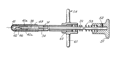
Referring to F~GS. 1, 2A and 2B, one embodiment of
the present removal tool generally comprises a tubular
body 31 with a longitudinal bore 33 therethrough. The
bore 33 has a substantially uniform diameter. The body 31
mdy be formed of silicone or other relatively soft
flexible material. The overall diameter of body 31 i8
relatively ~msll, so that it ~ay be used in the urethra or
other narrow body passaqe without undue discomfort or
trauma.
A magnet enclosure 34 is a cylindrical sleeve-like
member inserted in the bore 33 and is slidable therein
along the longitudinal axis of the bore 33. Because the
bore 33 has a substantially uniform diameter, the
enclosure 3~ may generally slide the len~th of the bore
33, although, as will be more fully described below, its
forward ~ovement i~ li2ited by a tubing ~top 46.
35The enclosure 34 has a first or plunger bore 35 and a
second or m2gnet bore 37, each concentric with the bore 33
6~6
and aligned along the longitudinal axis of the enclosure
34. The bores 35 and 37 have a shoulder 36 therebetween.
The ~houlder 36 is circumferential about the bore 37 and
lies in a plane perpendicular to the longitud~nal axis of
the bores 35 and 37.
A magnet 38 i9 ~ylindrical in shape and is slidably
positioned within the bore 37. In its fully withdrawn
position, the aft end of the magnet 38 abuts the shoulder
36. The bore 37 and the magnet 38 both have a greater
diameter than the bore 35.
Extending through the bore 33 of the body 31 and
through the bore 35 of the enclosure 34 is a plunger or
shaft 32. The shaf~ 32 i5 generally rod-like in shape.and
may protrude past the shoulder 36 into the bore 37. A
first, distal, or forward end of the shaft 32 which
extends throuqh the bore 35 to the shoulder 36 is joined
to a first, rearward, or proximal end of the magnet 38
positioned within the bore 37. Thus, longitudinal
movement of the plunger 32 within the bores 33 and 35
causes corresponding longitudinal movement of the magnet
38 within the bore 37 and may cause the magnet 38 to
extend out of the bore 37. As mentioned above,
longitudinal movement of the magnet 38 into the bore 37 is
limited by the shoulder 36.
A second, distal, or forward end of the maqnet 38 has
its circular edge bevelled, indicated at 44, so as to
engage the interior faces 39 and 40 of jaw halves 41 and
42 in a manner to be more fully described.
The jaws 48 include jaw halves 41 and 42 which join
to form balloon-shaped jaws having a generally smooth
outer surface for sliding in and out of the tubing 31.
Semi-cylindrical arms 41a and 42a of the jaw halves 41 and
~2806SG
42, respectively, abut and join to ?n end face of the
enclosure 34 adjacent the bore 37. The arms 41a and 42a
join to form a cylindrical shape having a bore 37a of
diameter substantially equivalent to that of ~he bore 3~
and aligned alon~ the same longitudinal axis. The outside
diameter of the cylinder shape formed by the arms 41a and
42a is smaller than the outside diameter of the enclosure
34, resulting in a circumferential ~houlder or jaw step 43
at the junction with the enclosure 34.
The bore 37a terminates interior to the jaw ~alves 41
and 42 in a cone with faces 39 and 40 defining the surface
of the coneO The faces 39 and 40 are each semi-conical
and extend from the outer diameter of the bore 37a at
lS their base to the longitudinal axis of the bore 37a at
their apex.
The magnet 38, when the plunger 32 is displaced
longitudinally inward, is able to extend into the bore 37a
of the iaws 48 such that the bevelled edge 44 will engage
the faces 39 and 40. As can be seen in ~IG. 2B, continued
longitudinal displacement of the shaft 32 will cause the
jaws 48 to extend out of the tubing 31 and will cause the
edge 44 of the magnet 38 to force the faces 39 and 40
forward and apart, separating the jaw halves 41 and 42 and
opening the jaw~ 4B. The magnet 38 may then protrude
through the open ~aw~ 48 and attract an object ~uch as a
ferrous ball 12.
Contained within the jaws 48 is a cavity 45. The
cavity 45 may be for~ed by two hemispherical cavities, one
for~ed in each of the jaw halves 41 and 42. When the jaws
48 are opened by longitudinal movement o~ the magnet 38,
the cavity 45 is opened and capable of receiving an object
such as a ball 12. When the jaws 48 are closed, the
~8~;5~
cavity 45 is a closed sphere which may trap or hold a ball
or other object.
The enclosure 34 and the jaws 48 together make up a
generally cylindrical grasping mechanism or receptacle
having bores 37 and 37a internal thereto for housing the
magnet 38 which is slidable within the bores. The
grasping mechanism or receptacle is itself slidable within
the bore 33, limited by the tubing stop 46. The shaft
bore 35 in the enclosure ~4 receives the shaft 32 for
connection to the magnet 38. Moving together, the shaft
~2 and the magnet 38 serve to actuate the jaws 48 from
their normally-closed first position to an open second
position for receiving objectc in the cavity 45.
In their normal or closed position, the jaw~ 4B are
withdrawn into the tubing 31 with an end of the tubing 31
having a circumferential lip 47 generally encircling the
jaws 48. Adjacent the lip 47 and internal to the bore 33
is an inwardly projectin~ tubing stop 46 which is si~uated
about the circumference of the bore 33. The tubing stop
46 engages the jaw step 43 when the enclosure 34 is moved
toward the lip 47, and thereby limits the longitudinal
movement of both the enclosure 34 and the jaws 48~ In
this forward position, the jaws 48 protrude past the lip
47 and out of the bore 33 and are in position to open in
response to further forward movement of the shaft 32 in
the bore 33.
39 Overlaying the tubing body 31 and extending
substan~ially its length i8 a sleeve or skin ~9. The
sleeve 49 functions as a skin and may be constructed of
qilicone or similar material capable of stretchin~. In
instances where the jaws 48 are allowed to protrude
slightly from the bore 33, the skin 49 preferably extends
over the lip 47 for joinder to the jaw halves 41 and 42.
~2~06~6
With such a construction, the skin 49 will stretch as the
iaWs 48 a~e extended out of the bore 33 and will regain
its normal form as the jaws 48 are once again withdrawn
into the bore 33. The sleeve 49 may be used ~o cover the
lip 47 and provide a smooth surface without edges for
insertion into a urethra.
The end of body or tubing 31 opposite the jaws 48
terminates in a disk or handle 54. The handle 54 may be
joined t~ the tubing 31 in a variety of well known ways,
including the use of shoulders 60 external to the tubing
31 and internal to the handle 54 for mutual engagement.
The tubing 31 and the handle 54 may also be joined using
various bonding means.
The shaft ~2 extends beyond the bore 33 and through
the handle 54 and terminates in a knob 51 which is
longitudinally spaced from the handle 54. The knob 51 is
retained on the shaft 32 using a set screw 52 or other
suitable means. Intermediate the handle 54 and the knob
51 is a spring 53 tending to maintain a separation between
the handle 54 and the knob 51. The spring 53 thus biases
the magnet 38 in a withdrawn position within the enclosure
34 and biases the jaws 48 toward a closed position within
the tubing 31.
The handle 54 may include grips 61 for use in
conjunction with the knob 51 to compress the spring 53.
Moving the knob 51 toward the handle 54 causes the shaft
32 to slide within the bore 33. The magnet 38 is thereby
made to actuate the jaws 4B as described above.
FIG. 3 shows an alternate embodiment of ~he present
invention wherein the shaft 32 of FIGS. 1 and 2 has been
eliminated. The mechanism for actuating the jaws 48 and
the magnet 38 may be pneumatic or hydraulic in nature.
65i~
The rearward end 61 of the body 31 is adapted to receive a
syringe or similar means for injecting a liquid or gaseous
substance into the bore 33. The injected substance,
preferably a relatively incompressible material, begins to
fill the bores 33 and 35.
When sufficient pressure has developed in the bores
33 and 35, the magnet 38 is forced forward into abutting
relationship with the surfaces 39 and 40 on the interior
of the jaws 48 and the magnet enclosure 34 is forced
forward until shoulder 43 abuts the stop 46. The
injection of additional fluid or gas into the bore 33
results in an increasing pressure within bores 33, 35 and
37. Again, when sufficient pressure has developed, the
magnet 38 forces the jaws 48 open and the magnet 38 may
protrude through the open jaws 48.
The magnet 38 is prevented from completely exiting
the jaws 48 by means of cooperating shoulders 62 and 63 on
the magnet enclosure 34 and the magnet 38, respectively,
by similar means.
As in the preferred embodiment 3hown in FIG. 1, when
the magnet 38 protrudes through the open jaws 48, it may
a~tract a ferrous ball which is connected to a urethral
device. When the object has been attracted by the magnet
38, the pressure within the bores 3~, 35 and 37 may be
released by withdrawal of the syringe from the body 31 or
by any other suitable method.
Springs 66 and 67 connected between the magnet 38 and
the enclosure 34 and between the enclosure 34 and the body
31 bias the magnet 38 and the enclosure 34 toward a
position within the bore 33. As in the case of the
preferred embodiment shown in FIGS. 1, 2~ and 2B, the jaws
48 are biased toward a closed position by the nature of
ll
their connection to the enclosure 34 and by the inwardly
directed radial force exerted by the lip 47 and the body
31 as the jaws 48 are withdrawn into the bore 33.
S The enclosure 34 and the magnet 38 ~ay be provided
with circumferential seals 68 to prevent the escape of
fluid or gas pressure as the magnet 38 and the jaws 48 are
actuated. It will be obvious to those skilled in the art
that other suitable means may be utilized for the purpose.
The embodiment illustrated in FIG. 3 provides remote
control of the capturing mechanism and will have an
advantage in that it may generally be made of a smaller
overall diameter because an internal shaft is not needed.
~owever, certain disadvantages, such as reliability and
controllability, may be realized.
A removal tool according to the present invention may
be utilized to remove a urinary continence device which
includes inflatable anchors for retainin~ the device in
position within a urethra. Generally, such a device may
include a pull plug on its lower end which, when removed
from its plugging position, allows anchoring collars to
deflate so that the device may be withdrawn from the
urethra. In accordance with the device, the pull plug may
have attached to it a ball or other object which may be
easily grasped and pulled. The tool illustrated in Figure
1 i5 designed for use with such a continence device.
Figure 4 illustrates a urinary continence device 14
positioned within a male urethra and having a small ball
12 of ferrous material or material containing ferrous
inserts attached to its pull plug (not shown) by means of
12
a suture 13. A removal tool 14 is shswn in position
within the urethra and the jaws 48 are shown in position
near the ferrous ball 12.
When it is desirable to remove the continence device
14 from the urethra, the removal tool 10 i~ inserted into
the urethra and is guided along the urethra to the ball 12
attached to the pull plu~. The tubular body 31 is of a
soft pliable material so that it may be inserted through
the urethra without significant difficulty or trauma.
When the proximal or forward end of tbe tool 10 nears the
ferrous ball 12, the knob 51 i~ pu~hed toward the handle
54, compressinq the spring 53 and urging the shaft 32 i~to
t~e bore 33. As the ~agnet 38 is urged toward the faces
39 and 40 of the jaws 48, the enclosure 34 and the jaws 48
are caused to move forward protrudinq from the bore 33
until the jaw step 43 encounters the tubing stop 46. The
tubing stop 46 limits the forward, outward projection of
the jaws 48 and continued longitudinal m~vement of the
shaft 32 and the magnet 38 causes the magnet 38 to part
the jaw halves 41 and 42, opening the jaws 48. Further
movement of the magnet 38 causes it to protrude from the
open jaws and to attach itself to the ferrous ball 12.
When the ball 12 has been captured by the magnet 38,
the knob 51 is withdrawn causing the magne~ 38 to be once
again withdrawn within the jaw~ 48. When the magnet 38
has been sufficiently withdrawn, the jaw halves 41 and 42
rejoin and the ball 12 i~ captured within the cavity 45.
Continued withdrawal of the ma~net 3~ by pullin~ on the
knob 51 results in the ~2gnet 38 engaging the sh~ulder 36
and forcing a withdrawal of the jaws 48 into the tubing
31.
By applying a slight pulling force to the tool 10,
the pull plug, being attached to the ball 12 by suture 13,
`~
13
is disengaged from the continence device 14, causing the
inflatable cuf~s or collars 11 to deflate~ Once the
anchorin~ mechanism ~or the continence device 14 has been
released, a steady pull on the t~ol 10 will force a
withdrawal of the devi~e 14 from the urethra.
It will now be recognized that a new removal tool has
been provided that can be conveniently utilized to remove
a urinary continence device from a urethra without
significant difficulty or trauma. Application of the
invention will include tools for removin~ many types of
objects from narrow body passages. Although the above
description describes detail~ of a preferred embodiment of
the present invention, it will be understood by those
skilled in the art that numerous other embodiments and
applications of the invention may exist or be developed.
For example, the body 31 may be eliminated and the
enclosure 34 may be lengthened sufficiently to extend out
of the urethra. The sleeve~like enclosure 34 will then
function as both the body 31 and the enclosure 34.
Although in many such applications/ all of the advantages
of the illustrated embodiment may not be achieved, certain
desirable attributes may be attainable. The scope of the
present invention should accordingly be limited only by
the scope of the appended claims.