Language selection

Search

Patent 1280816 Summary

Third-party information liability

Some of the information on this Web page has been provided by external sources. The Government of Canada is not responsible for the accuracy, reliability or currency of the information supplied by external sources. Users wishing to rely upon this information should consult directly with the source of the information. Content provided by external sources is not subject to official languages, privacy and accessibility requirements.

Claims and Abstract availability

Any discrepancies in the text and image of the Claims and Abstract are due to differing posting times. Text of the Claims and Abstract are posted:

  • At the time the application is open to public inspection;
  • At the time of issue of the patent (grant).
(12) Patent: (11) CA 1280816
(21) Application Number: 517292
(54) English Title: FEEDBACK CONTROL FOR AUTOMATIC FILLING MACHINE
(54) French Title: COMMANDE A RETRO-ACTION POUR MACHINE DE REMPLISSAGE AUTOMATIQUE
Status: Deemed expired
Bibliographic Data
(52) Canadian Patent Classification (CPC):
  • 341/97
(51) International Patent Classification (IPC):
  • B65B 1/12 (2006.01)
  • B65B 1/32 (2006.01)
  • G01G 13/29 (2006.01)
  • G01G 15/00 (2006.01)
(72) Inventors :
  • IZZI, ANTHONY J. (United States of America)
(73) Owners :
  • MATEER-BURT CO., INC. (United States of America)
(71) Applicants :
(74) Agent: GOWLING WLG (CANADA) LLP
(74) Associate agent:
(45) Issued: 1991-02-26
(22) Filed Date: 1986-09-02
Availability of licence: N/A
(25) Language of filing: English

Patent Cooperation Treaty (PCT): No

(30) Application Priority Data:
Application No. Country/Territory Date
872,367 United States of America 1986-06-09

Abstracts

English Abstract


FEEDBACK CONTROL FOR
AUTOMATIC FILLING MACHINE

Abstract Of The Disclosure
An apparatus for automatically adjusting a preselected
volume of material dispensed by a volumetric filling machine
into containers to be filled by weight. The apparatus has
means for sequentially weighing a plurality of containers
each containing the preselected volume of material dispensed
by the filling machine and sequentially generating an equal
plurality of weight signals representative of the weight of
the dispensed material in the containers. A microprocessor
means receives and stores the sequential weight signals and
stores them in a memory, and calculates an average weight
value. The microprocessor means then compares the average
weight value to a preselected weight value and generates a
correction signal representative of the comparison. Means
responsive to the correction signal adjusts the preselected
volume by an amount sufficient to cause the average weight
value to be equal to the preselected weight value.


Claims

Note: Claims are shown in the official language in which they were submitted.


-12-
CLAIM
1. Apparatus for automatically adjusting a preselected
volume of material dispensed by a volumetric filling machine
into containers to be filled by weight, comprising
(a) means for sequentially weighing a plurality
of containers each containing the preselected volume of
material dispensed by the volumetric filling machine and
sequentially generating an equal plurality of weight signals
representative of the weight of the dispense material in
the containers,
(b) means for receiving the sequential weight
signals and storing them in a memory,
(c) means operatively associated with the
receiving means for calculating from the stored sequential
weight signals an average weight value,
(d) means operatively associated with the cal-
culating means for comparing the average weight value to a
preselected weight value and generating a correction signal
representative of the comparison, and
(e) means responsive to the correction signal
for adjusting the preselected volume by an amount sufficient
to cause the average weight value to be equal to the pre-
selected weight value.
2. Apparatus for automatically adjusting a preselected
volume of material dispensed by a volumetric filling machine
into containers to be filled by weight, comprising
(a) means for sequentially weighing a plurality
of containers each containing the preselected volume of
material dispensed by the volumetric filling machine and
sequentially generating an equal plurality of weight signals
representative of the weight of the dispense material in
the containers,
(b) means for receiving the sequential weight
signals and determining whether the weight signals are with-
in preselected tolerance limits,
(c) means for rejecting weight signals outside
the preselected tolerance limits and storing signals within
the preselected tolerance limits,

-13-
(d) means operatively associated with the
receiving means for calculating from the stored sequential
weight signals an average weight value and a range value
equal to the difference between the maximum stored sequen-
tial weight signal and minimum stored sequential weight
signal,
(e) means for printing each stored sequential
weight value, the average weight value and the range value,
(f) means operatively associated with the cal-
culating means for comparing the average weight value to a
preselected weight value and generating a correction signal
representative of the comparison, and
(g) means responsive to the correction signal
for adjusting the preselected volume by an amount sufficient
to cause the average weight value to be equal to the pre-
selected weight value.
3. In an automatic filling machine for volumetri-
cally dispensing a preselected weight of material into con-
tainers to be filled by causing a rotary dispensing means
to rotate through a predetermined number of revolutions,
the number of revolutions being proportional to the volume
of material dispensed, apparatus for automatically adjust-
ing the predetermined number of revolutions, comprising:
(a) means for sequentially weighing a plurality
of containers each containing the amount of material dis-
pensed by the predetermined number of revolutions of the
dispensing means and sequentially generating an equal
plurality of weight signals representative of the weight of
the dispensed material in the containers,
(b) means for receiving the sequential weight
signals and storing them in a memory,
(c) means operatively associated with the
receiving means for calculating from the stored sequential
weight signals an average weight value,
(d) means operatively associated with the cal-
culating means for comparing the average weight value to a
preselected weight value and generating a correction signal
representative of the comparison, and

-14-

(e) means responsive to the correction signal
for adjusting the predetermined number of revolutions by an
amount sufficient to cause the average weight value to be
equal to the preselected weight.
4. In an automatic filling machine according to
claim 3, wherein the sequential weighing means comprises an
electronic scale.
5. In an automatic filling machine according to
claim 3, wherein the calculating means and the comparison
means comprise a microprocessor.
6. In an automatic filling machine for volumetri-
cally dispensing a preselected weight of material into con-
tainers to be filled by causing a rotary dispensing means
to rotate through a predetermined number of revolutions,
the number of revolutions being proportional to the volume
of material dispensed, apparatus for automatically adjust-
ing the predetermined number of revolutions, comprising:
(a) an electronic scale for sequentially weigh-
ing a plurality of containers each containing the amount
of material dispensed by the predetermined number of
revolutions of the dispensing means and sequentially gen-
erating an equal plurality of weight signals representative
of the weight of the dispensed material in the containers,
(b) means for receiving the sequential weight
signals and determining whether the weight signals are
within preselected tolerance limits,
(c) means for rejecting weight scales outside
the preselected tolerance limits and storing signals within
the preselected tolerance limits,
(d) means operatively associated with the
receiving means for calculating from the stored sequential
weight signals an average weight value and a range value
equal to the differnce between the maximum stored sequential
weight signal and minimum stored sequential weight signal,
(e) means for printing each stored sequential
weight value, the average weight value and the range value,


-15-

(f) means operatively associated with the cal-
culating means for comparing the average weight value to a
preselected weight value and generating a correction signal
representative of the comparison, and
(g) means responsive to the correction signal
for adjusting the predetermined number of revolutions by an
amount sufficient to cause the average weight value to be
equal to the preselected weight.
7. In an automatic filling machine according to
claim 6, wherein the calculating means and the comparison
means comprise a microprocessor.
8. In an automatic filling machine for volumetri-
cally dispensing a preselected weight of material into con-
tainers to be filled by causing a rotary dispensing means
to rotate for a predetermined time, the time being propor-
tional to the volume of material dispensed, apparatus for
automatically adjusting the time of revolution, comprising:
(a) means for sequentially weighing a plurality
of containers each containing the amount of material dis-
pensed by the predetermined time of revolution of the dis-
pensing means and sequentially generating an equal plurality
of weight signals representative of the weight of the dis-
pensed material in the containers,
(b) means for receiving the sequential weight
signals and storing them in a memory,
(c) means operatively associated with the
receiving means for calculating from the stored sequential
weight signals an average weight value,
(d) means operatively associated with the cal-
culating means for comparing the average weight value to
a preselected weight value and generating a correction
signal representative of the comparison, and
(e) means responsive to the correction signal
for adjusting the predetermined time of revolution by an
amount sufficient to cause the average weight value to be
equal to the preselected weight.


-16-
9. In an automatic filling machine according to
claim 8, wherein the sequential weighing means comprises
an electronic scale.
10. In an automatic filling machine according to
claim 8, wherein the calculating means and the comparison
means comprise a microprocessor.
11. In an automatic filling machine for volumetri-
cally dispensing a preselected weight of material into con-
tainers to be filled by causing a rotary dispensing means
to rotate for a predetermined time, the time being propor-
tional to the volume of material dispensed, apparatus for
automatically adjusting the time of revolution, comprising:
(a) an electronic scale for sequentially weigh-
ing a plurality of containers each containing the amount
of material dispensed by the predetermined time of revolu-
tion of the dispensing means and sequentially generating
an equal plurality of weight signals representative of the
weight of the dispensed material in the containers,
(b) means for receiving the sequential weight
signals and determining whether the weight signals are
within preselected tolerance limits,
(c) means for rejecting weight scales outside
the preselected tolerance limits and storing signals within
the preselected tolerance limits,
(d) means operatively associated with the
receiving means for calculating from the stored sequential
weight signals an average weight value and a range value
equal to the difference between the maximum stored sequential
weight signal and minimum stored sequential weight signal,
(e) means for printing each stored sequential
weight value, the average weight value and the range value,
(f) means operatively associated with the cal-
culating means for comparing the average weight value to
a preselected weight value and generating a correction
signal representative of the comparison, and
(g) means responsive to the correction signal
for adjusting the predetermined time of revolution by an


-17-

amount sufficient to cause the average weight value to be
equal to the preselected weight
12. In an automatic filling machine according to
claim 11, wherein the calculating means and the comparison
means comprise a microprocessor.
13. Method of automatically adjusting a preselected
volume of material dispensed by a volumetric filling machine
into containers to be filled by weight, comprising the
steps of
(a) sequentially weighing a plurality of con-
tainers each containing the preselected volume of material
dispensed by the volumetric filling machine,
(b) sequentially generating an equal plurality
of weight signals representative of the weight of the
dispensed material in the containers,
(c) receiving the sequential weight signals
and storing them in a memory,
(d) calculating from the stored sequential
weight signals an average weight value,
(e) comparing the average weight value to a
preselected weight value,
(f) generating a correction signal represen-
tative of the comparison, and
(g) adjusting the preselected volume by an
amount sufficient to cause the average weight to be equal
to the preselected weight value.
14. Method of automatically adjusting a preselected
volume of material dispensed by a volumetric filling machine
into containers to be filled by weight, comprising the
steps of
(a) sequentially weighing a plurality of con-
tainers each containing the preselected volume of material
dispensed by the volumetric filling machine,
(b) sequentially generating an equal plurality
of weight signals representative of the weight of the
dispensed material in the containers,


-18-

(c) receiving the sequential weight signals
and determining whether the weight signals are within pre-
selected tolerance limits,
(d) rejecting weight signals outside the pre-
selected tolerance limits and storing signals within the
preselected tolerance limits in a memory,
(e) calculating from the stored sequential
weight signals an average weight value and range value
equal to the difference between the maximum stored sequen-
tial weight signal and minimum sequential weight signal,
(f) comparing the average weight value to a
preselected weight value,
(g) generating a correction signal represen-
tative of the comparison, and
(h) adjusting the preselected volume by an
amount sufficient to cause the average weight to be equal
to the preselected weight value.

15. Method according to claim 14, further comprising
the step of printing the store sequential weight values,
the average weight value and the range value.
16. Method of automatically adjusting a predetermined
number of revolutions of a rotary dispensing means in an
automatic filling machine for volumetrically dispensing a
preselected weight of material into containers to be filled
by causing the rotary dispensing means to rotate through a
predetermined number of revolutions proportional to the
volume of material dispensed, comprising the steps of
(a) sequentially weighing a plurality of con-
tainers each containing the amount of material dispensed
by the predetermined number of revolutions of the dis-
pensing means,
(b) sequentially generating an equal plurality
of weight signals representative of the weight of the dis-
pensed material in the containers,
(c) means for receiving the sequential weight
signals and storing them in a memory,


-19-
(d) means operatively associated with the
receiving means for calculating from the stored sequential
weight signals an average weight value,
(e) means operatively associated with the cal-
culating means for comparing the average weight value to
a preselected weight value,
(f) generating a correction signal represen-
tative of the comparison, and
(g) adjusting the predetermined number of
revolutions by an amount sufficient to cause the average
weight value to be equal to the preselected weight.
17. Method of automatically adjusting a predetermined
number of revolutions of a rotary dispensing means in an
automatic filling machine for volumetrically dispensing a
preselected weight of material into containers to be filled
by causing the rotary dispensing means to rotate through a
predetermined number of revolutions proportional to the
volume of material dispensed, comprising the steps of
(a) sequentially weighing a plurality of con-
tainers each containing the amount of material dispensed
by the predetermined number of revolutions of the dis-
pensing means,
(b) sequentially generating an equal plurality
of weight signals representative of the weight of the dis-
pensed material in the containers,
(c) means for receiving the sequential weight
signals and determining whether the weight signals are
within preselected tolerance limits,
(d) rejecting weight signals outside the pre-
selected tolerance limits and storing signals within
the preselected tolerance limits in a memory,
(e) means operatively associated with the
receiving means for calculating from the stored sequential
weight signals an average weight value and a range value
equal to the difference between the maximum stored sequen-
tial weight signal and minimum sequential weight signal,


-20-

(f) means operatively associated with the cal-
culating means for comparing the average weight value to
a preselected weight value,
(g) generating a correction signal represen-
tative of the comparison, and
(h) adjusting the predetermined number of
revolutions by an amount sufficient to cause the average
weight value to be equal to the preselected weight.
18. Method according to claim 17, further comprising
the step of printing the stored sequential weight values,
the average weight value and the range value.
19. Method of automatically adjusting a predetermined
number of revolutions of a rotary dispensing means in an
automatic filling machine for volumetrically dispensing a
preselected weight of material into containers to be filled
by causing the rotary dispensing means to rotate for a
predetermined time proportional to the volume of material
dispensed, comprising the steps of

(a) sequentially weighing a plurality of con-
tainers each containing the amount of material dispensed
by the predetermined time of revolution of the dispensing
means,
(b) sequentially generating an equal plurality
of weight signals representative of the weight of the dis-
pensed material in the containers,
(c) means for receiving the sequential weight
signals and storing them in a memory,
(d) means operatively associated with the
receiving means for calculating from the stored sequential
weight signals an average weight value,
(e) means operatively associated with the cal-
culating means for comparing the average weight value to
a preselected weight value,
(f) generating a correction signal represen-
tative of the comparison, and
(g) adjusting the predetermined time of revolu-
tion by an amount sufficient to cause the average weight
value to be equal to the preselected weight.

-21-

20. Method of automatically adjusting a predetermined
number of revolutions of a rotary dispensing means in an
automatic filling machine for volumetrically dispensing a
preselected weight of material into containers to be filled
by causing the rotary dispensing means to rotate for a
predetermined time proportional to the volume of material
dispensed, comprising the steps of
(a) sequentially weighing a plurality of con-
tainers each containing the amount of material dispensed
by the predetermined time of revolution of the dispensing
means,
(b) sequentially generating an equal plurality
of weight signals representative of the weight of the dis-
pensed material in the containers,
(c) means for receiving the sequential weight
signals and determining whether the weight signals are
within preselected tolerance limits,
(d) rejecting weight signals outside the pre-
selected tolerance limits and storing signals within the
preselected tolerance limits in a memory,
(e) means operatively associated with the
receiving means for calculating from the stored sequential
weight signals an average weight value and a range value
equal to the difference between the maximum stored sequen-
tial weight signal and minimum sequential weight signal,
(f) means operatively associated with the cal-
culating means for comparing the average weight value to
a preselected weight value,
(g) generating a correction signal represen-
tative of the comparison, and
(h) adjusting the predetermined time of revolu-
tion by an amount sufficient to cause the average weight
value to be equal to the preselected weight.
21. Method according to claim 20, further comprising
the step of printing the stored sequential weight values,
the average weight value and the range value.


-22-

22. Apparatus for automatically adjusting a preselec-
ted volume of material dispensed by a each of a plurality
of individual volumetric filling machines into containers
to be filled by weight, comprising
(a) a single means for sequentially weighing a
plurality of containers from one of the individual filling
machines, each container containing the preselected volume
of material dispensed by the individual volumetric filling
machine associated with that plurality of containers and
sequentially generating an equal plurality of weight signals
representative of the weight of the dispense material in
the containers,
(b) switch means for directing the plurality of
weight signals to a selected one of the individual filling
machines,
(c) means at each filling machine for receiving
the sequential weight signals and storing them in a memory,
(d) means at each filling machine operatively
associated with the receiving means for calculating from
the stored sequential weight signals an average weight
value,
(e) means at each filling machine operatively
associated with the calculating means for comparing the
average weight value to a preselected weight value and
generating a correction signal representative of the compa-
rison, and
(f) means at each filling machine responsive
to the correction signal for adjusting the preselected
volume by an amount sufficient to cause the average weight
value to be equal to the preselected weight value.


Description

Note: Descriptions are shown in the official language in which they were submitted.


1~30~3~6


FEEDBACK CONTROL FOR
AU~OMATIC FILLING MAC~IINE
_ackground Of The Invention
The basic concept of filling containers by dispensing
materials from a hopper using a rotary feed mechanism is
well known. Such apparatus can be used for volumetric
filliny of free-Elowing and non-free-flowing granular,
powdered, flaked or paste material. Typically, the feed
mechanism is positioned in an opening in the bottom of a
vertically-disposed conical hopper and consists of either
an auger or a pump. The auger, pump rotor, or other rota-
tional member is driven by a prime mover, such as an elec-
tric motor, through a clutch-brake mechanism which connects
the driving shaft of the motor to the driven shaft of the
rotational member. The clutch-brake mechanism is controlled
to rotate the driven shaft for a pre-selected number of
revolutions by a device which counts the number of revolu-
tions. This is a relatively accurate way of volumetrically
dispensing material since the amount of material dispensed
by each revolution of the auger or pump can be accurately
determined. For example, for each revolution of an auger
of known pitch and diameter, the volume of material dispen-
sed from its discharge end can be determined. By appro~
priate control, the auger can be made to run through sequen-
tial cycles of a predetermined number of turns. During
each cycle, thereEore, a predetermined volume of material
is discharged into a container positioned by mechanized
packaging devices beneath the discharge end of the feed
L~f
1112-33 CN


.

a~
-2-

mechanism. Mechanized packaging line devices for se~uen-
tially positioning containers made of paper, metal, plastic
or glass are well known.
Since each revolution of the feed mechanism dispenses
a known amount of material, it follows that the number of
revolutions is a measure of the volume of material that has
been dispenseda There are two methods for determining the
number of revolutions. The first method is to directly
count the number of revolutions. The second method is to
measure the time period over which the feed mechanism is
being driven at a constant speed. In known apparatus,
devices for counting the number of revolutions include
counters directly linked by gearing the output side of the
clutch-brake mechanism mentioned above, and shaft encoders
directly or indirectly coupled to the driven shaft which
generate a given number of pulses for each complete revolu-
tion of the driven shaft. When the correct count is reached,
the driven shaft is disengaged from the driving shaft and
braked by the clutch-brake mechanism.
The timed method of controlling the number of revolu
tions is less accurate than the count method, although in
certain cases the timed method of controlling the number of
revolutions may yield acceptable accuracy.
~ s noted above, known filling machines operate in a
volumetric mode. That is, for an auger of known pitch and
diameter, each revolution of the auger dispenses a given
volume. However, in many instances, the material being
filled into the container is ultimately sold to the consumer
by weight, not volume~ Thus, in order to fill a one-pound
coffee can with one pound of coffee, for example, the
filling machine must dispense a particular volume of coffee
which will have a weight of one pound. Obviously, the
weight of the material dispensed is equal to the product of
the density of the material times the volume dispensed.
Variations in density, due to factors such as temperature,
humidity or other factors, will result in different weights
of material for a given volume, and these factors can change
within a production run.


,:


: '

~28~)8~6
--3-

It is an ob ect o~ the invention to provide a s~lf-
correcting feedback control system for auger fillers which
can adjust filler settings to compensat~ for product density
changes and the like, and therefore changes in weight of
dispensed material, without interrupting production.
Summary Of The Invention
The present invention provides apparatus for auto-
matically adjusting a preselected volume of material dis-
pensed by a volumetric filling machine into containers to
be filled by weight. The apparatus comprises means for
sequentially weighing a plurality of containers each of
which contains the preselected volume of material dispensed
by the filling machine and sequentially generating an equal
plurality of weight signals representative of the weight of
the dispensed material in the containers. Means are pro-
vided for receiving the sequential weight signals and
storing them in a memory. Means operatively associated
with the receiving means are provided for calculating from
the stored weight values an average weight value. Means
operatively associated with the calculating means are pro-
vided for comparing the average weight value to a preselec-
ted weight value and generating a correction signal repre-
sentative of the comparison. Means responsive to the
correction signal are provided ~or adjusting the preselected
volume by an amount sufficient to cause the average weight
value to be equal to the preselected weight value.
In one embodiment of the invention t the invention
provides apparatus for automatically adjusting the predeter-
mined number of revolutions in an automatic filling machine
for volumetrically dispensing a preselected weight of
material into containers to be filled by causing a rotary
dispensing means to rotate through a predetermined number
of revolutions. In this embodiment of the invention,
means are provided responsive to the correction signal for
adjusting the predetermined number of revolution by an
amount sufficient to cause the average weight value to be
equal to the preselected weight.
. ~ .

- ~L280a~6

~,

The invention a~so incllldes a method of automatically
adjusting a preselected volume of material dispensed by a
volumetric fillinq machine into containers to be illed by
weight, and comprises the steps of sequentially weighing a
plurality of containers each containing the preselected
volume of material dispensed by the filling machine, sequen--
tially generating an equal plurality of weight signals rep-
resentative of the weight of the dispensed material in the
container, receiving the sequential weight signals and
storing in them in a memory, calculating from the stored
sequential weight signals an average weight value, compar-
ing the average weight value to a preselected weight value,
generating a correction signal representative of the com~
parison, and adjusting the preselected volume by an amount
sufficient to cause the average weight to be equal to the
preselected ~eight value.
In one method according to the invention, the method
includes automatically adjusting a predetermined number
of revolutions of a rotary dispensing means in an automatic
filling machine for volumetrically dispensing a preselected
weight of material into containers to be filled by causing
the rotary dispensing means to rotate through a predeter-
mined number of revolutions proportional to the volume of
material dispensed. In this method, the predetermined
number of revolutions is adjusted by an amount sufficient
to cause the average weight value to be equal to the pre~
selected weight.
~ In both the apparatus and method, the invention is
! not limited to adjustment of the number of revolutions of
a dispensing means but includes automatically adjusting a
predetermined time of revolution of a rotary dispensing
means, the time of revolution being proportional to the
volume of material dispensed. That is, the invention is
applicable to automatic filling machines which operate in
both revolution-controlled and time-controlled dispensing
modes.
.' ~

~LZ80~3~6
5--

Detailed Description Of The Drawings
For the purpose of illustrating the invention, there
is shown in the drawings a form which is presently pre-
ferred; it being understood, however, that this invention
is not limited to the precise arrangements and instrumen-
talities shown.
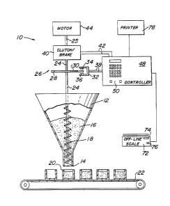
Figure 1 illustrates in schematic form a filling appa-
ratus equipped with feedback control in accordance with
the present invention.
Figure 2 illustrates a typical operator control panel
of an apparatus in accordance with the present invention.
Figure 3 is a block diagram of one embodiment of a
control means for the present invention~
Figure 4 is a flow chart illustrating the operation
of the feedback control according to the present invention.
Figure 5 is a much-simplified block diagram showing
how the present invention can be applied to a number of
individual filler lines operating in parallel.
Detailed Description Of The Invention
Referring now to the drawings, wherein like numerals
indicate like elements, there is shown in Figure 1 in
schematic form a filling apparatus 10 e~uipped with feed-
back control in accordance with the present invention.
Apparatus 10 has a hopper 12 for storing material to be dis-
pensed. Hopper 12 has generally the shape of an inverted
cone. The bottom end of hopper 12 terminates in generally
cylindrical outlet 14.
A rotary dispensing means in the form of a feed
auger 18 is fitted within the outlet 14 at the bottom end
of hopper 12. Rotation of the auger 18 causes material 16
to be dispensed from hopper 12 through outlet 14 into
containers 20 which are positioned manually or by a conveyor
22 beneath hopper 12. Conveyor 22 may be any well-known
and widely employed conveyor for indexing individual con-
tainers to ~e filled beneath hopper outlet 14.
`~ It should be understood that by illustrating an auger
there is no intention to limit the invention to filling

'1~80~16
--6--

machines which utilize an auger. Auger 18 cou:ld just as
well be a screw rotor of a Moyno type pump. However, for
purposes of illustrating the invention, reference will be
made to an auger.
Auger 18 may be caused to rotate by means of auger
shaft 24. The lower end of shaft 24 may be integral with
or otherwise securely fastened to auger 18. The upper end
of shaft 24 is connected through clutch-brake 40 to driving
motor 44~ For purposes of illustrating the invention,
clutch-brake 40 and motor 44 are coupled by shat 25.
Clutch-brake 40 and motor 44 may be any conventional motor
and clutch brake. Such devices are well-known and widely
used in the art and need not be explained here in detail.
A shaft encoder assembly 26 is coupled to auger shaft
24. Shaft encoder assembly 26 may be an electrooptic shaft
encoder. Alternatively, shaft encoder 26 may be any type
of shaft encoder which generates signals indicative of the
rotation of auger shaft 2~. In the particular embodiment
illustrated in Figure 1, shaft encoder 26 consists of a
disk 28 which is coupled to shaft 24 so as to rotate with
it. The function of disk 28 is to act as a light chopper.
For this purpose, it is provided with a plurality of slots,
lines or holes 30 which are evenly spaced about its per-
iphery~ The number of slotsl lines or holes 30 can be
varied. However, for convenience the disk 28 may have 100
slots, thereby providing a number which is easily divisible
to indicate a complete revolution of shaft 24 and hence
auger 18. A bracket 32 supports a light source 34. Light
source 34 may be the ~ilament of an incandescent lamp or a
light emitting diode which generates a constant light
output. Bracket 32 also supports a photodetector 36, such
as a phototransistor or the like, which is sensitive to
the light energy generated by the light source 34.
The light source 34 and the photo detector 36 are posi-
tioned by the bracket 32 in opposing relation adjacent the

- ~soal~
--7--

peripheral edge of the disk 28. Thus, Iight energy emitted
by the light source 34 must pass through the slots 30 in
the disk 28 in order to be detected by the photodetector 36.
As a result, the output of the photodetector 36 will be a
series of discrete electrical pulses whose frequency will
depend upon the speed at which the shaft 24 is rotating.
Likewise, the number of pulses generated in a given interval
will indicate the extent to which shaft 24, and hence auger
18, has revolved in that interval.
The pulses generated by shaft encoder assembly 26 are
fed to a controller 48 via wires 38. Similarly, clutch-
brake 40 is connected to controller 48 by wires 42. Con-
troller 48, which will be described in greater detail below,
receives the pulses generated by shaft encoder assembly 26,
processes them and generates control signals which control
the operation of clutch-brake 40. Controller 48 is provided
with a control/display panel sn which may display machine
status and other information to an operator, and by means
o~ which an operator may provide various inputs to control-
ler 48.
Controller 48 also receives inputs from an off~line
scale 72, located off conveyor 22 out of the normal flow of
filled containers 20. Scale 72 may be an electronic scale
or strain gauge, which generates an output weight signal
representative o~ the weight of an item placed on scale 72.
Scale 72 has a display 74 and an "initiate" control 76, dis-
cussed in greater detail below.
A printer 78 may be connected to controller 48 to pro-
vide a "hard copy" of data displayed on control/display
panel 50, or of any other data desired, with suitable
programming of controller 48.
Control/display panel 50 is shown in greater detail
in Figure 2. Control/display panel 50 has a display sec-
tion 52, which may be an LED display or liquid crystal dis-
play, or any other display suitable for displaying alpha-
numeric information to an operator. Display 52 may serve
to dis~lay machine status, veriy inputs entered by an

0 8
--8--
-


operator, or display instructions to an operator to "prompt",
or assist, the operator in providing necessary inputs or
aid the operator in trouble shooting.
Adjacent display sect;on 52 is an operator-actuated
keyboard or push button assembly 54. This may be used by
an operator to enter commands to the machine, enter data
requested by the controller 48, and otherwise permit the
operator to communicate with controller 48. Control panel
50 may also include start and stop buttons 56 and 58 for
initiating and terminating machine operation.
Controller 48 is illustrated in greater detail in
block diagram form in Figure 3. The heart of controller 48
is a microprocessor 60, which can be programmed to monitor
and direct any number of machine functions. The operation
of microprocessor 60 is synchronized with the remainder of
the machine by input from shaft encoder 26 via versatile
interface adapter (V.I.A.) and timer/counter interface 64.
Operator inputs may be entered into microprocessor 60 via
asynchronous control interface assembly (A.C.I.A.) 62,
which translates operatorentered inputs from keyboard
assembly 52 into a form usable by microprocessor 60.
Likewise, A.C.I.A. 62 converts prompt and other messages
generated by microprocessor 60 into operator-readable form
for display by display section 52. The microprocessor 60
also receives inputs from other portions of the apparatus
l0, such as the pulses generated by shaft encoder assembly
26, and generates control outputs to clutch-brake 40.
Encoder pulses go directly into the V.I.A. 64. Other
inputs and outputs are coupled to microprocessor 60 by
means of I/O module 68. Controller 48 also includes a
memory 66 which may be used to store data, commands and
other information required by the microprocessor 60 or the
operator to carry out various machine functions. Power
supply 70 may be any conventional power supply and converts
input power in the form of 120 V ac or 240 V ac into a dc
voltage suitable for the controller electronics.
Although it is not necessary for understanding of the
present invention, for a more detailed description of the

~80a~

g
operation of filler 10 and controller 48, reference may be
mads to Canadian patent no. 1,227,855, i~sued on October 6,
1987 and assigned to the assignee o~ the present application.
The function of the feedback control of the pre~ent
invention is to ad~ust the number of auger rsvolutions (or
the time of auger revolution; for simplicity, the following
discussion is directed only to adjustment of number of auger
ravolutions) preselected by an operator by means of
controller 48 to compensate for welght fluctuations in filled
containers. With the present invention, the controller 48
will receive a preselected number of filled container weight
values from scale 72, calculate ths average of these values,
then compare the averaged weight to the target weight value
re~iding in memory 66 of the controller 48. If this
aomparison indicates a difference between the average weight
value and the target weight value, microprocessor 60 will
automatically adjust the preselected number of auger
revolutions to correct for the entire difference.
Operation of the feedback control will now be
described.
At the beginning of a filling operation, the operator
enters the target weight of material to be filled into
containers 20 into memory 66 of controller 48 along with
information about the number of packages desired in a batch
for aYeraging weights. The operator will al~o have entered
information which enables controller 48 to calculate the
number of auger revolutions necessary to dispense the target
weight. All entries are made through push button assembly
54. Once the filling operation ha~ begun, at regular or
random intervals the operator removes contalners 20 from
conveyor 22 to be weighed by scale 72. Display 74 on ~cale
72 displays the weight of a selected container 20. As long
as the weight displayed by saala 72 is within acceptable
limits, the filling operation can proceed as originally
programmed. However, lf scale 72 indicates that the weights
of selected containers 20 are outside an acceptable range,
the operator begins the feedback control operation.

08~1.6
--10--

In the feedback control operation, the operator
weighs a predetermined batch number of packages in order
to arrive at an average weight value. As each package is
weighed by scale 72, the weight signal gerlerated by scale
72 is sent to controller 48 when the "initiate" control 76
is depressed by the operator. As each weight signal is
received by controller 48, it is displayed on display
section 52 of controller 48. Microprocessor 60 then ana-
lyzes the weight data and calculates a correction factor.
This correction factor is used to alter the number of
auger revolutions required to dispense the target weight.
Operation of the feedback control system is graph-
ically depicted in the flow chart of Figure 4. In Figure
4, the appreviation "WV" represents the "weighment value"
or weight signal generated by scale 72; "Y" represents the
number of samples to be weighed in a batch; "TW" represents
target weight; and "R" represents the "range" or difference
between the maximum and minimum weighment values in a
batch.
; When a batch of containers 20 are to be weighed, the
operator places the container on scale 72 and depresses
the "initiate" switch 76. This causes the scale 72 to send
the weighment value to controller 48. When controller 48
receives the weighment value from scale 72, it determines
whether or not the weighment value is within a sample error
tolerance preselected by the operator. If the weighment
value is not within the preselected sample error, the
weighment value and sample number are ignored. I~ the
weighment value is within the sample error, controller 48
then determines whether or not the number of weighment
values received from scale 72 is equal to the number of
samples to be weighed in the batch. The sample number is
incremented by one each time a weighment value within the
sample error is received from scale 72. If the scale
sample number is less than the batch sample number, the
weighment value and sample number are stored. Weighment
values are stored until the scale sample number is equal

8iL6
-


to the batch sample number. When that occurs, indicating
that all of the containers in the batch have b~en weiqhed,
controller 48 calculates an avera~e weighment value and
the range between the maximum and minimum weighment val~es
in the batch. If desired, this average weighment value
and range may be output to printer 78~
Controller 48 also compares the average weighment
value to the target weight entered into memory 60 by the
operator. If there is a difference between the average
weighment value and target weight, the number of auger
revolutions, or "turns", is adjusted to account for 100~
of the difference between the average weighment value and
target weight. That is, the number of auger revolutions
is either increased or decreased so that the weight of
material dispensed by the ajusted number of auger revolu-
tions will be equal to the target weight. If there is no
difference between the average weighment value and the
target weight, indicating that is no need to adjust the
number auger revolutions, the scale sample number is reset
to one and the stored weighment values are reset to zero.
he present invention may operate with several fillers
at one time. As shown in Figure 5, four fillers lOa-lOd
may receive inputs via their respective controllers 48a-48d
by means of a selector switch 80. To control a given one
of the fillers lOa-lOd, all the operator need do is select
the appropriate filler at selector switch 80 prior to begin-
ning the feedback control operation.
The present invention may be embodied in other speci-
fic forms without departing from the spirit or essen-
tial attributes thereof and, accordingly, reference should
be made to the appended claims, rather than to the foregoiny
specification, as indicating the scope of the invention.

Representative Drawing
A single figure which represents the drawing illustrating the invention.
Administrative Status

For a clearer understanding of the status of the application/patent presented on this page, the site Disclaimer , as well as the definitions for Patent , Administrative Status , Maintenance Fee  and Payment History  should be consulted.

Administrative Status

Title Date
Forecasted Issue Date 1991-02-26
(22) Filed 1986-09-02
(45) Issued 1991-02-26
Deemed Expired 2005-02-28

Abandonment History

There is no abandonment history.

Payment History

Fee Type Anniversary Year Due Date Amount Paid Paid Date
Application Fee $0.00 1986-09-02
Registration of a document - section 124 $0.00 1986-12-09
Maintenance Fee - Patent - Old Act 2 1993-02-26 $100.00 1992-12-16
Maintenance Fee - Patent - Old Act 3 1994-02-28 $100.00 1993-12-22
Maintenance Fee - Patent - Old Act 4 1995-02-27 $100.00 1995-01-18
Maintenance Fee - Patent - Old Act 5 1996-02-26 $150.00 1996-01-12
Maintenance Fee - Patent - Old Act 6 1997-02-26 $150.00 1997-01-14
Maintenance Fee - Patent - Old Act 7 1998-02-26 $150.00 1998-01-07
Maintenance Fee - Patent - Old Act 8 1999-02-26 $150.00 1999-01-05
Maintenance Fee - Patent - Old Act 9 2000-02-28 $150.00 1999-12-20
Maintenance Fee - Patent - Old Act 10 2001-02-26 $200.00 2001-01-18
Maintenance Fee - Patent - Old Act 11 2002-02-26 $400.00 2002-09-12
Maintenance Fee - Patent - Old Act 12 2003-02-26 $200.00 2002-09-20
Owners on Record

Note: Records showing the ownership history in alphabetical order.

Current Owners on Record
MATEER-BURT CO., INC.
Past Owners on Record
IZZI, ANTHONY J.
Past Owners that do not appear in the "Owners on Record" listing will appear in other documentation within the application.
Documents

To view selected files, please enter reCAPTCHA code :


To view images, click a link in the Document Description column. To download the documents, select one or more checkboxes in the first column and then click the "Download Selected in PDF format (Zip Archive)" or the "Download Selected as Single PDF" button.

List of published and non-published patent-specific documents on the CPD .

If you have any difficulty accessing content, you can call the Client Service Centre at 1-866-997-1936 or send them an e-mail at CIPO Client Service Centre.


Document
Description 
Date
(yyyy-mm-dd) 
Number of pages   Size of Image (KB) 
Representative Drawing 2001-11-05 1 12
Drawings 1993-10-15 4 112
Claims 1993-10-15 11 504
Abstract 1993-10-15 1 29
Cover Page 1993-10-15 1 15
Description 1993-10-15 11 555
Fees 2002-09-12 1 49
Fees 2002-09-20 1 37
Fees 2000-02-09 1 45
Fees 1997-01-14 1 74
Fees 1996-01-12 1 79
Fees 1995-01-18 1 68
Fees 1993-12-22 1 70
Fees 1992-12-16 1 44