Note: Descriptions are shown in the official language in which they were submitted.
"3~-~
BROKEN BOLT EXTRACTOR
Background
The present invention relates to extractors for
removing broken threaded fasteners such as studs from broken
bolts and more particularly to a broken fastener extractor
combined with a drill head in a single combination tool.
The present invention is an improvement over my prior
U.S. patent entitled "Easy-Out Threaded Fastener" filed March 12,
1985 now U.S. patent number 4,604,917.
Conventional easy out type bolt extractors for
extracting broken bolt studs within a threaded bore are formed
with gripping teeth and/or shaped flutes adapted to engage the
sides of a previously drilled bore through the broken bolt stud.
The gripping surfaces remove the threaded bolt stud when the
extractor is rotated in a direction opposite to that of the bolt
threads. These extractors require that the hole be drilled first
through the broken bolt stud prior to the insertion of the
extractor. A shortcoming of this tool is that the drill bit is
often broken in the process of drilling which results in a
~0 compound problem of removal of both the broken bolt stud and the
broken drill bit. Even when the drill bit is not broken, the
bolt stud is often driven deeper into the threaded hole making
extracting more difficult. This process requires that the drill
bit be removed before inserting the bolt extractor so that at
least three separate operations are needed using at least three
separate tools including a drill bit, a tap wrench and extractor.
-- 1 --
~,
~- -l .
.
'' ;' ` '
3~7
Summary of the Inventlon
The invention in its broader claimed aspect pertains to
a tool assembly for extracting a broken threaded fastener
threaded in a first direction of tightening in a fastener bore.
The assembly includes drill means for forming a drill bore in the
broken fastener upon rotation in a second direction opposi-te to
the first direction, shaft means extending from the drill means
for rotating the drill means and coupling means for coupling a
drive tool to an end of the shaft means remote from the drill
means. Extractor means is disposed on the shaft means and
gripping means cooperates with the extractor means for enabling
the extractor means to grip the interior of the drill bore so as
substantially to prevent rotation of the extractor means relative
to the drill bore. Connector means interconnects the shaft means
and the extractor means for producing an axial displacement along
the shaft means of the extractor means towards the drill means
when rotation of the extractor means is substantially prevented.
Expander means cooperates with the extractor means for engaging
the extractor means and stopping the axial dlsplacement, the
expander means expanding the extractor means for gripping the
interior of the drill bore, whereby continued rotation of the
drive means in the second direction extracts the fastener from
the fastener bore.
More particularly, the present invention combines the
drill bit for forming a bore within a broken bolt stud and bolt
extractor for removing the broken bolt stud in a single tool.
The lower surface of the tool is provided with a drill bit having
a cutting edge threaded with a pitch in the direction opposite to
the threads of the broken bolt stud being extrac-ted and a drill
2 -
. ` , ` . . ' `
: - .
body having a truncated surface which tapers outwardly toward the
drill bit. The drill body is connected to a threaded shaft, the
upper portion of which includes a drive head for a suitable hand
or power driven tool. A bolt extractor means or collet is
threadedly mounted on the drill bit shaft between the drill bit
and the drive head.
To remove a broken bolt stud which remains within a
threaded fastener bore, the dxill bit engages the broken bolt
stud and driving of the drive head drills a hole within the body
of the broken bolt stud. As the tool penetrates within the
broken bolt stud, the extractor means or collet, which is
threadedly mounted on the drill bit shaft, engages the interior
of the drill hole being bored in the broken bolt stud. At that
point, the drilling mode stops and the drill bit is rotated out
of the drill bore toward the extractor collet by the reverse
threads on the drill bit shaft. As the drill bit shaft and drill
bit aredriven outwardly from the drill bore, the interior surface
of the extractor collet engages the truncated surface on the
drill body causing a lower resilient portion of the extractor
~0 collet to expand out within the broken bolt stud. Because the
extractor and the drill bit have been ro-tated together, they act
as a single unit and therefore, continued rotation of the tool
will unthread the broken bolt stud to extract it from the
fastener bore.
Among the aspects of the present invention are the
provision of a threaded fastener extractor tool which is combined
with a drilling bit so that a broken bolt may be removed in a
single operation.
-- 3
- .
, . . . . .
' : .~, , . ' .
- . ' ' : ,
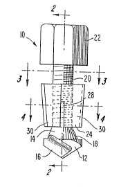
~escription of the Drawings
FIGURE 1 is an elevational view of the bolt extractor
tool assembly of the present invention.
FIGURE 2 is a sectional view taken along the lines
2 - 2 of FIGURE 1.
FIGURE 3 is a sectional view taken along the lines
3 - 3 of FIGURE 1.
FIGURE 4 is a sectional view taken along the lines
4 - 4 of FIGURE 1.
Description of Preferred Embodiments
Referring now to the drawings, FIGURES 1 to 4
illustrate an easy-out type of bolt extractor 10 of the present
invention. The lower portion of the bolt extractor 10 includes a
drill bit 12 which is used to drill a bore within a broken bolt
stud (not shown) to be extracted. The drill bit 12 includes a
drill body 14 and cutting edges 16. The drill body 14 is formed
with a truncated outer surface 18. Assuming most broken bolts
which are to be removed have right-handed threads, cutting edges
16 of the drill bit 12 are provided with a left-handed or
2~ counterclockwise cutting pitch. The drill body 14 is integrally
connected to a tool shaft 20 which is threaded with right-handed
or clockwise threads in a pitch opposite to that of the cutting
edges 16 of the drill bit 12. The truncated surface 18 of the
drill body is tapered outwardly from the point where the drill
body 14 attaches to the threaded tool shaft 20 toward the cutting
edges 16.
The upper end of the tool shaft 20 is formed with a
drive head 22 adapted to be driven by a suitable driving means
such as a power tool chuck or hand driven wrench. Although not
~ 4
.
,
.
.. ~ ; , ,
'
shown, it will be apparent to those skilled in the art that drive
head 22 and the upper end of shaft 20 are preferably cons-tructed
such that drive head 22 is secured to shaft 20 af-ter the
extractor or collet is located on shaft 20.
The extractor tool 10 includes an extractor collet 24
having an internally threaded bore which acts as a connecting
means between the collet 24 and the threaded tool shaft 20. The
collet 24 has a tapered exterior with gripping means in the form
of fluted teeth 26 adapted to grip an interior bore surface
formed by the drill bit 12 as described hereinbelow. Also the
extractor collet 24 is formed with a series of longitudinal slots
28 which separate the extractor collet 24 into a series of
segments 30, each segment 30 having one of the fluted teeth 26.
The slots 28 provide resiliency to and allow for expansion of the
lower end of the segments 30. The extractor collet 24 is
reciprocally and rotatably moveable along the longitudinal axis
of the threaded tool shaft 20 by the relative movement of the
interior threads of the extractor collet 24 and the threads on
the tool shaft 20.
~0 In use a stud remaining in a threaded fastener bore
when a bolt is broken may be extracted by the easy-out broken
bolt extractor tool 10 of the present invention. A bore within
the broken bolt stud is drilled by using a suitable drivi.ng tool
rotated in a left-handed or counterclockwise direction to drive
the drill bit 12 of the extractor tool 10 into the broken bolt
stud. As the drill bit 12 penetrates the broken bolt stud, the
tapered fluted teeth 26 of the extractor collet 24 engage the
interior wall of the bore being drilled within the broken bolt
stud. Once the collet 24 is engaged in the broken bolt stud,
. - 5 -
.
: ' ~ - ,.' , '. .
.
3~7
continued rotation of the extractor tool 10 by the driving tool
means causes the drilling mode -to stop. The drill bit 12 is
rotated out of the bore in the broken bolt stud because of the
reverse threaded connection between the colle-t 24 and the
threaded shaft 20, causing the drill bit lZ to move toward the
extractor collet 24. The drill bit 12 and the extractor collet
24 become engaged and the resilient segments 30 of the extractor
collet 24 are expanded outwardly by the camming action of the
truncated surface 18 (expander means) against the interior
surfaces of the segments 30. The outward expansion of the collet
segments 30 causes the fluted teeth 26 to securely grip the
interior of the drill bore~ Thus joined, the extractor collet
24, the driven tool shaft 20 and drill bit 12 act as a single
unit and continuous driving of the tool 10 in the
counterclockwise direction provides an extracting force to
unthread the broken bolt stud.
It will be appreciated that various changes and
modifications may be made to the above-described invention within
the scope of the appended claims.
6--