Note: Descriptions are shown in the official language in which they were submitted.
1~8~3~
SPECIFICATION
Title of the Invention:
MAGNETIC TRANSDUCER HEAD UTILIZING
MAGNETORESISTANCE EFFECT
Back~round of the Invention ~
The present invention relates to a magneto-
resistance effect type magnetic transducer head
~hereinafter referred to as a MR magnetic head).
In the conventional MR magnetic head known
heretofore, generally the sensing element comprises a
single MR magnetic layer, and a sensing current is fed to
flow in the plane direction of the MR magnetic layer and
also in the direction transverse the track of its surface
so that it opposes a magnetic recording medium so that a
resistance variation, which is deceived from a signal
magnetic field which is applied to the MR magnetic layer,
is detected in the form of, for example, a voltage
variation. In other words, the sensing current flows in
the MR magnetic layer perpendicular to the signal
magnetic field which is applied from the magnetic
recording medium. In the case o~ using a single MR
magnetic layer, the magnetic thin film has a
-2-
B
~a~3~
domain structure so as to maintain a state where -the sum
of the magnetic anisotropy eneryy, the magnetostatic
energy resulting from shape anisotropy and so forth is
minimized for the entire magnetic layer. The maynetic
eneryy is stable when the magnetic film is divided into a
plurality of magnetic domains, as explai,ned hereinafter
in the present specification. When the external magnetic
field is applied to the magnetic film, magnetization of
the magnetic film causes domain wall displacement. The
domain wall displacement causes the Barkhausen noise
which is not desirable for reproducing operation of the
magnetoresistance effect type magnetic transducer head.
Object and Summary of the Invention
Accordingly, it is an object of the present
invention to provide an improved magnetic transducer head
utilizing the magnetoresistance effect.
It is another object of the present invention
to provide a magnetic transducer head utilizing the
magnetoresistance effect which effectively avoids the
generation of Barkhausen noise.
It is a further object of the present invention
to provide a magnetic transducer head utiliziny
~;B
~LZ~3~13~
the magnetoresistance effect and has an improved signal
to noise ratio.
According to one aspect of the prese.nt
invention there is provided a magnetic transducer head
utilizing the magnetoresistance effect whlch comprises a
sensing element composed of first and second soft
magnetic layers superposed on each other and has a non
magnetic layer between the first and second soft magnetic
layers, with at least one of the soft magnetic layers
having a magnetoresistance effect and the first and
second soft magnetic layers being magnetostaticaly
coupled through the non magnetic layer,
a pair of electrodes being connected to said
sensing element at first and second end portions of the
sensing element so as to cause the flow of a sense
current through the sensing element in one direction
between the first and second end portions,
the sensing element receiving a signal magnetic
field which is parallel to said one direction, and
the soft magnetic layers having an easy axis of
magnetization substantially perpendicular to said one
direction or having an isotropic magnetic characteristic
in a major surface of the soft magnetic layer.
. ~
~ 3'~
Brief Descri~tion of the Drawings
Fig. 1 is a schematic enlarge~ plan view of an
exemplary MR type magnetic head according to the present
invention,
Fig. 2 is a cross-sectional view taken along
the A - A line in Fig. 1,
Fig. 3 shows the magnetization state of a
sensing element employed in the present invention,
Figs. 4A through 4C show the magneti2ation
state of the sensing element upon application of an
external magnetic field thereto,
Figs. 5 through 7 show the operation of the
magnetic transducer head according to the present
invention,
Fig. 8 is a sectional view of another magnetic
transducer head according to the present invention,
Figs. 9 through ll show plan views of other
embodiments of sensing elements according to the
present invention,
Fig. 12 is 3n enlargea plan view of further
embodiment of the magnetic transducer head according to
the present invention,
Fig. 13 is a sectional view taken ~long A - A
line in Fig. 12,
B - 5 -
~L2B~3~
Fig. 14 is a schematic illustratlon of the
magnetic domain structure formed in a prior art single
layer MR magnetic thin film,
Fig. 15 shows magnetization state of the
sensing element for comparison MR head,
Figs. 16 and 17 shown plan views of the
sensing element used for explaining the present
invention, and
Fig. 18 as a graph showing the MR
characteristics curve to explain the present invention.
Description of the Preferred ~mbodiments
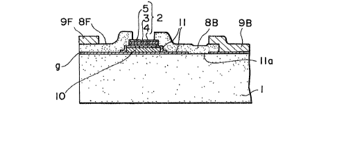
As shown in the plan view of Fig. 1 and a
sectional view of Fig. 2 a MR magnetic head of the
present invention is mounted on a substrate 1`, and has a
thin-film sensing element 2 which has a magnetoresistance
effect.
A surface is in contact with or is opposed to a
magnetic recording medium 7, which is transported in a
direction perpendicular to the drawing paper face in
Fig.1.
In the present invention, the sensin~ element 2
is of a laminated structure where magnetic layers 4 and 5
of a soft magnetic material are superposed with
.~
a nonmagnetic intermediate layer 3 between them, and at
least one of such magnetic layers exhibits the
magnetoresistance effect. The thickness of the
nonmagnetic intermediate layer 3 is selected to be
greater than 5A and less than 10,000~, e.g. within a
range of 5 to 500~ so as to cause magnetostatic
interaction between the two magnetic layers 4 and 5 which
is more dominant than an exchange interaction. The
saturation flux density, thickness and other properties
of the magnetic layers 4 and 5 are properly selected so
as to obtain mutual equalization of the magnetic flux so
that the magnetic flux as a whole is closed with respect
to the two magnetic layers 4 and 5.
In case the two magnetic layers 4 and 5 of the
sensing element 2 are both formed of a material having
magnetoresistance effect, it is to be desired that the
two layers 4 and 5 be composed of the same material and
be equal to each other in shape and size. However, when
merely one of them is composed of a material which has
little or no MR effect, the material and thickness of
this magnetic layer can be selected so that a
sufficiently great resistance is obtained as compared
with the other magnetic layer which has a MR effect. In
this case, it is necessary to satisfy the condition that
the magnetic flux quantities of both magnetic layers are
equal to each other.
3~
In the present invention, a signal magnetic
field Hs is applied from a magnetic recording medium to
the sensing element 2 and a sensing current l is fed so
as to flow in the sensing element 2 and is arranged to
act in the same direction, and each of the magnetic
layers constituting the sensing element 2 is formed so as
to have an easy axis of magnetization which is
perpendicular to the signal magnetic field or to be
isotropic without having anisotropy in the principal
plane of the magnetic layer.
In a state when no signal magnetic field is
applied to the sensing element 2, a required bias
magnetic field is applied from an external source in a
manner such that magneti~ation is effected at a
predetermined angle of, e.g. 45, to the direction of the
senslng current l.
According to the above-mentioned structure of
the present invention, Barkhausen noise can be
effectively eliminated as will be described below.
The generation of Barkhausen noise in the
conventional MR magnetic head which has a sensing element
which comprises a single MR magnetic layer, such layer
has a magnetic domain structure as shown in Fig. 14 so as
to maintain a state where the sum of the magnetic
anisotropy energy, the magnetostatic energy
-8-
. r~
~i ~
l~a~
resulting from shape anisotropy is minimized ~ith
respect to the entire layer. In the case of a single
magnetic layer which is a rectangular thin-film magnetic
layer 51 which has magnetic anisotropy in its shor-t-side
or transverse direction, the maynetic domains 52
alternately reverse relative to the direction of the
transverse magnetization which are produced in the film
plane, and sequentially reverse magnetic domains 53 are
produced between the end so that adjacent magnetic
domains 52 in the long-side or longitudinal direction of
the magnetic layer in such a manner that a closed loop is
formed with regard to the adjacent magnetic domains 52.
There*ore, if an external magnetic field is applied to
such magnetic layer, domain walls 54 and 55 are displaced
to consequently generate Barkhausen noise.
In the construction of the present invention
which differs from the above, magnetic layers 4 and 5 are
superposed with a nonmagnetic intermediate layers 3
therebetween so that, when no external magnetic field is
applied, the magnetic layers 4 and 5 are magnetized in
mutually reverse parallel directions along the re~spective
e.asy axes of magnetization as indicated by arrows Ml and
M2 in Fig. 3, and no magnetic domain wall exists. The
nonexistence of any domain wall has been confirmed
_9_
~.Z~ 3~
through observation of magnetic domains by the sitter
process using a magnetic fluid. When an external
magnetic field H is gradually increased in intensity
along the hard axis of magnetization of such sensiny
element 3, as typically shown in Fig. 4 A throuyh C where
solid-line arrows represent the maynetized state of the
magnetic layer 5 and broken-line arrows represent that of
the magnetic layer 4, the magnetization is rotated by
the external magnetic field H from the mutually reverse
parallel state of Fig. 4 A described in connection with
Fig. 3 to the state of Fig. 4 B.
~hen a higher-intensity external magnetic field is
applied, the magnetic layers 4 and 5 are magnetized in
the same direction as shown in Fig. 4 C. In this case,
the magnetization is rotated in the planes of the
magnetic layers 4 and 5, so that no domain wall is
produced which avoids the generation of Barkhausen noise.
That is, by causing the flux flow to be coincident with
the hard axes of magnetization in both of the magnetic
layers 4 and 5, it becomes possible to avoid the
Barkhausen noise that results from domain walls
displacement.
Now the operation of the magnetic head
according to the present invention will be described
-10-
~'~ 8~ ~ 3'~
below witn reference to Figs. 5 through 7, which
typicallv show merely tne two magnetic layers 4 and 5 of
the sensing element 2. In the initial state, the
magnetic layers 4 and 5 have easy axes of magnetization
in the directions indicated by e.a in Fig. 5, and a
sensing current 1 is so ~s to ~low in the magnetic layers
4 and 5. Such energization generates mutually reverse
magnetic fields perpendicular to the current flow in the
magnetic layers 4 and 5 mutually spaced with a nOnmAgnetiC
intermediate layer (.not shown), therebetween whereby the
magnetic layers 4 and 5 are magnetized as indicated by a
solid-line arrow. Ml and a broken-line arrow M2.
When an external bias magnetic field HB is
applied to the sensing element 2 in the direction of
the cur~ent-i, then the directions of magnetization of
the magnetic layers 4 and 5 are rotated a required angle
as indicated by arrows MBl and MB2 in Fig. 6. The
intensity of the bias magnetic field HB is so selected
that the direction of magnetization determined by such
magnetic field ~B has an angle of approximately 45 to
the flow of the current i. The procedure ~or obtaining
high sensitivity and linearity by applying the bias
magnetic field HB to induce magnetization of
approximately 45 to the sensing current i i similar to
~2~ 3~
that executed with respect to an ordinary MR magnetic
head. In the above state, when a signal magnetic fiel~
Hs is applied in the direction of the sensing current
or along the hard axis of magnetization as shown in Fig.
7, the direction of magnetization is rotated clockwise
and counterclockwise respectively throuyh anyles of 91
and -~1 as indicated by arrows Msl and Ms2.
Consequently, if both magnetic layers 4 and 5 are made of
a material which has a MR effect, resistance variations
occur therein. Since the resistance variation in each MR
magnetic layer is proportional to cos2~ (where ~ is an
angle variation), when the magnetization directions MB1
and MB2 in the layers 4 and 5 have a difference of 90 as
shown in Fig. 6, the increases or decreases caused in the
resistance variations relative to the two magnetic layers
4 and 5 by angle variations ~1 and -~1 are coincident
with each other. That is, if the resistance of one
magnetic layer 4 increases, the resistance of the other
magnetic layer 5 also increases in the direction to
increase. A resistance variation is induced between
terminals tl and t2 of the sensing element 2 due to the
resistance variations in the magnetic layers ~ and 5, and
such resistance variation can be detected in the form of
a voltage variation between the terminals tl and t2.
-12-
~.r~a~32
Thus, in the present invention, the direction
of a sensing current i relative to a magnetic film having
a prescribed magnetic anisotropy is selectively set to
coincide with the direction in which a signal maynekic
field Hs is applied. With such construction where the
sensing element 2 comprises the magnetic layers 4, and 5
and a nonmagnetic intermediate layer 3 sandwiched
therebetween as in the above-described invention, the
advantageous features will become more obvious by
comparison with an example where the direction of the
sensing current i is set to be perpendicular to the
direction of the signal magnetic field Hs. That is, as
shown Fig. 15 where a large current 1 is applied to the
two magnetic layers 4 and 5 with the anisotropic magnetic
field Hk thereof taken into consideration as described
previously in connection with Fig. 5, a magnetic field is
generated and results in magnetizing the magnetic layers
4 and 5 perpendicularly to the current 1 as indicated by
a solid line and a broken line respectively. When a
signal magnetic field Hs is applied in this structure
perpendicularly to the current 1, it coincides with the
direction of magnetization caused by the current 1 in the
magnetic layers 4 and 5, and the magnetic field Hs
behaves in the same manner as
-13-
B
.. ,
~ 3'~
in the case of application along the easy axis of
magnetization. Consequently, there are generated
magnetic domain walls and displacement thereof which
eventually induce Barkhausen noise. In a construction
where a sensing current l is fed so as to flow along the
easy axis of magnetization in the magnetic layer and a
signal magnetic field Hs is applied in the same direction
as the sensing current, the magnetic layer fails to be
magnetized perpendicularly to the sensing current l if
this current is relatively small, so that the signal
magnetic field Hs is applied substantially along the easy
axis of magnetization as in Fig. 15, whereby the
undesired result is the generation of Barkhausen noise.
Although in the example of Figs. 5 through 7 a
description has been given with respect to a magnetic
layer which has an easy axis of magnetization
perpendicular to the signal magnetic field Hs, a similar
effect is attainable also by the use of an isotropic
magnetic layer which has no magnetic anisotropy in its
principal plane. In this case, the flow of a relatively
small sensing current renders the direction of
magnetization perpendicular to the sensing current and
hence to the signal magnetic field and avoids the
generation of Barkhaus~n noise.
-14-
,
~Lza~3~
In the constitution of the present invention,
as described above, t~e magnetic layers 4 and 5 o~ the
MR sensing element 2 are magnetostatically coupled to
each other due to the presence of a nonmagnetic
intermediate layer 2 ~hich is sandwiched therebetween, so that
exchange interaction can be neglected while a
sufficiently firm magnetostatic coupling is ensured by
the interaction based on Coulomb's law, and - -
Barkhausen noise can be eliminated as the
signal magnetic field Hs and the sensing current 1 are
directionally colncident with each other.
The present invention is applicable to a
variety of MR type magnetic heads of different
structures including a nonshielded head, a shi.elded
head, and a yoke type head where a signal magnetic flux
picked up from a surface in contact with or opposed to a
magnetic recording medium is introduced by means of a
magnetic yoke and an MR sensing element is disposed in a
cut portion formed in the magnetic yoke.
Hereinaf~er a preferred embodiment o~ the
present invention will be descrlbed in detail with
reference to Figs. 1 and 2. This embodiment represents
an exemplary constitution of a yoke type MR head.
- 15 -
~ ~ 8~ ~3
In this example, a substrate 1 is compose~ o~
a magnetic material such as Ni-Zn ferrite, ~n-Zn ferrite
or the like. In case the substrate 1 is conductive,
first an insulating layer 11 of SiO2 or the like is
formed thereon, subsequently a bias conductor 10 is
formed on the layer 11 to generate a bias magnetic field
when energized,and another insulating layer 11 is formed
on the bias conductor 10 so as to form ~ MR sensing element
2. This element 2 extends perpendicularly to a surface
6 which is to be in contact with or is opposed to a
magnetic recording medium, and the bias conductor 10 is
so disposed as to traverse under the MR sensing element
2.
~ front ma~netic yoke 8F and a back magnetic
yoke 8B are disposed anterior and posterior to the MR
sensing element 2, i.e. at the two ends proximate to the
surface 6 and on the reVerse side, respetively. The two
magnetic layers 8F ànd 8B are co~posed of a metallic
material which is electrically conductive substantially
without M~ effect and has mag~etic anisotropy which is
perpendicular to a sensing current. Terminal conductive
layers 9F and 9B are electrically connected to the
magnetic layers 8F and 8B respectively, and terminals tl
and t2 are led out therefrom. In order to prevent
16 -
generation of Barkhausen noise whicll is caused by the
magnetic layers 8F and 8B, such layers may be superposed
with a nonmagnetic intermediate layer sandwiched
therebetween. A portion of the back magnetic layer 8B is
magnetically connected to the magnetic substrate
through a window lla formed in a nonmagenteic layer 11,
so that a closed magnetic path is formed by way of
substrate 1 - front magnetic layer 8F - MR sensing
element 2 - back maynetic layer 8B- substrate 1.
Between the fore end of the front magnetic layer 8F and
the substrate 1, there is formed a magnetic gap
confronting the surface 6 which is to be in contact with
or opposed to the magnetic recording medium, and the
length of such gap ~ is prescribed by the thickness of a
nonmagnetic layer such as the insulating layer 11.
The MR sensing element 2 can be continuously
produced in a single integrated step by the techniques
of sputtering or vacuum evaporation. That is, the
aforesaid magnetic layer 4, the nonmagnetic intermediate
layer 3 and the magnetic layer 5 are formed in sequence
by the use of a spattering apparatus or a vacuum
evaporation apparatus equipped respectively, with sputter
sources or evaporation sources of individual materials.
In the example illustrated, each of the magnetic layers
~25 -17-
3L~8~
4 and 5 has an eas~ axis of magnetization in the
direction indic~ted by e.a and a hard axis of
magnetization in the direction indicated by h.a. As
mentioned previously, each of the magnetic layers 4 and
5 may be composed of an isotropic magnetic film having
no anisotropy in its principal plane.
The nonmagnetic intermediate layer 3 is
composed of an insulating or conductive nonmagnetlc
material such as SiO2, Ti or the like, and its thickness
is selectively set to an adequate value of, e.g. 20~ so
that exchange interaction is substantially not exerted
between the two magnetic layers 4 and 5 and also such that
magnetostatic coupling is effected therebetween due to
the interaction according to Coulomb's law.
A~though the nonmagnetic intermediate layer 3
is formed so as to have an adequate thickness for
inducing magnetostatic coupling between the two magnetic
layers 4 and 5, practically the thickness required for
ensuring electrical insulation is about ten times
greater than the t~ickness selected for shutting off
magnetic exchange interaction. Therefore, when reducing
the thickness of the intermediate layer 3, electrical
connection is substantially effected between the two
magnetic layers 4 and 5. However, in case such
- 18 -
~'~ 8 ~ ~ 3~
electrical connection is not effected, it is necessary
to electric~lly connect the terminal conductive layers
9F and 9B respectively to the magnetic layers 4 and 5.
That is, in the above example, the magnetic layers 8F
and 8B need to be electrically connected respectively to
the magnetic layers 4 and 5 which constitute the sensing
element.
It is possible to electrically insulate t-he
magnetic layers 4 and 5 by the nonmagnetic intermediate
layer 3 with a sufficient thickness, and cause a sense
current in only one of the magnetic layers, In this
case, both of the magnetic layers are, of course,
magnetostatically coupled with each other, thought the
resistance change of only one magnetic layer is detected
upon application of this signal magnetic layer. By the
construction it is possible to increase the sensltivity
of the sensing element.
The layers 4 and 5 of the MR sensing element 2
may be formed of MR magnetic layers of the same
composition and of the same size and sh~pe with uniaxial
anisotropy or without anisotropy in the principal planes
thereof. Such MR magnetic layers may be composed of a
single metal such as Fe, Ni or Co, or an alloy o~ two or
more thereof.
B
- 19 -
~.~81'13'~
In the construction mentioned above, the
individual layers inclusive of insulating layer 11, bias
conductor 10, magnetic layers 4 and 5 of the sensing
element 2, nonmagnetic intermediate layer 3, magnetic
yokes 8F and 8B, and terminal conductive layers 9F and 9B
and so forth can be formed by sputtering or by
evaporation, and each can be shaped into a desired
pattern by photolithography technique.
In this construction, the sensing element 2 is
supplied with a dc sensing current 1 between its terminal
conductive layers 9F and 9B, hence between the magnetic
layers 8F and 8B, and a prescribed current which flows in
the bias conductor 10 so as to apply a required bias
magnetic field. In such a state, a magnetic recording
medium 7 is transported perpendicularly to the drawing
paper face of Fig. 1 while being kept in contact with or
opposite to the surface 6, whereby a signal magnetic flux
corresponding to the recorded magnetization on the medium
7 is picked up from the magnetic gap ~ is then fed to the
closed magnetic path formed by way of the aforesaid
magnetic layer 8F - MR sensing element 2 - magnetic layer
8B - substrate 1. Accordingly a signal magnetic field Hs
derived from the magnetic recording medium 7 is applied
-20-
~,~
, , , ,; . ~ ~ . .. . . ..
~L~ 3'~
to the MR sensing elPment 2 in the same direction as the
sensing cur.ent l. It follows, therefore, that the
recorded signal is read out from the magnetic recording
medium 7 while generation of Barkhausen noise is avoided
as described above.
In addition to the foregoing example where
both magnetic layers 4 and 5 of the MR sensing element
are formed of MR.layers, it-is possible to produce a
modification where merely one of the layers 4 and 5 is
formed of a magnetic layer having almost no MR effect
(hereinafter referred to asa non-MR magnetic layer). In
this case also the thickness and other conditions are so
selected that the amount of flux of the two magnetic
layers 4 and 5 become equal to each other as mentioned
previously. Meanwhile, the magnetic layer having almost
no MR effect may be composed of a high-resistivity,
high-permeability magnetic material such as amorphous
alloy of FeCoSiB, CoZr~b or Sendust alloy of Fe-Al-Si
which have high resistiYity so th~t the xes~stance between
the conductive magnetic layers 8F and 8B at the two ends
becomes sufficiently high to allow the sensing
current to flow principally in the magnetic layer having
MR effect. Another recommendable material for the high-
permeability magnetic layer having little MR effect ist
- 21 -
~ ~ 8 1 ~3'~
for example, Mo permalloy. Such material is of course
usable for the conductive magnetic layers 8~ and 83 as
well.
In addition to the above example where the
bias conductor lO is disposed under the sensing ele~ent
2 and an external magnetic field HB is applied to the
sensing element 2, the position and pattern of the bias
conductor lO ~ay be modified in various manners, and it
may be formed into a multilayer or ~ spiral structure.
Furthermore, the magnetic field to be applied is not
limited to one induced electrically, and a
permanent-magnet thin film is usable as well. Fig. 18
graphically shows the MR characteristic of the MR
sensing element a~cording to the present invention. The
curve represents the characteristic obtained when a
sensing current of lO mA is fed so as to f~ow in the sensing
element of 4 ~m x 4 ~m where magnetic layers of Ni-Fe
alloy having a thickness of 300~ are superposed with
an intermediate layer of SiO2 having a thickness of 40~,
and a magnetic field is applied in the same direction as
the sensing current. In this case, each of the magnetic
layers is composed of an isotropic film having no
magnetic anisotropy in its plane. AS is apparent from -
the graph, there is no generation of Barkhausen noise.
- 22 -
8~L3~
Besides the above example of a yoke type
structure where a closed maynetic path including the
sensing element 2 is formed by the magnetic substrate 1
and the magnetic layers 4 and 5, the invention may be
modified to another structure where the sensing element 2
substantially confronts the magnetic recording medium,
or to a single pole structure where a closed magnetic
path is not formed by the magnetic head itself.
Fig. 8 shows an example where the present
invention is applied to a shielded MR type magnetic head,
in which a sensing element 2 is spaced apart by a
predetermined distance as an insulating layer 11
interposed between two magnetic substrates 1 and 12.
However, the substrate 12 may be composed of a thin film
as well. In figure 8, terminal conductive layers 9F and
9B which are electrically connected to two magnetic
layers 4 and 5 superposed with a nonmagnetic intermediate
layer 3 therebetween. The discontinuous portion between
the conductive layers 9F and 9B functions as the sensing
element 2, and a sensing current i is fed to flow therein
as shown. The terminal conductive layer 9F may also
serve as a path for introducing a magnetic flux to the
sensing element 2, and it may be composed of a conductive
magnetic material having a thickness of 2000~ or so.
-23-
~ 3'~
Relative to this example, a type which has none
of the magnetic substrates l and 12 is termed a
nonshielded MR he~d.
In the~magnetic head of the present invention,
a sensing current is fed to flow in theMR sensing
element 2 perpendicularly to the track width WT as shown
in Fig. l, and the leakage magnetic field Hs from the
magnetic recording medium 7 is obtained by detecting the
resistance v~ri~tion~ between the fore end and the hind
end of the sensing element 2, whereby the recorded
signal is rep~oduced. In this stage, if the track width
WT corresponding to the width of the MR sensing element
2 is large, there arises a problem with respect to the
signal-to-noise ratio. That is, the signal magnetic
field Hs fr~m the recording medium 7 suddenly attenuates
with increase of the distance from the medium 7. such
attenuation changes depending on the wavelength and
tends to be greater as the wavelength becomes shorter.
It is desired that the MR sensing element 2 be disposed
within the effective reach of the magnetic field from
the recording medium 7. If disposed outside of such
reach, the sensing element 2 fails to function properly
and brings about reduction of the signal-to-noise ratio.
Suppose now that the depth DE equivalent to the reach of
- 24 -
~28~L~3~
the magnetic field from the recording medium is smaller
than the track width WT and, as shown in Fig. 16, the
length in the direction of the sensing current flow
through substantial current-conducting terminals l9F and
l9B at the two ends of the sensing element 2 is set to
be equal to the depth DE. Then, there arises a disadvantage
in that the resist~nce v~lue which is to be detected as
a resis~ance variation in the MR sensing element 2 fails
to be sufficiently large for easy signal processing. To
the contrary, if the above length of the MR sensing
element 2 is set to be greater than the extentof the
ma~netic field from the recording medium as shown in
Fig. 17, the ineffective portion is rendered large to
eventually bring about reduction of the signal-to-noise
ratio. Thus, the problem of the resistance value and
that of the signal-to-noise ratio are incompatible with
each other. Meanwhile, the Barkhausen noise suppression
effect becomes higher as the current density increase5.
It is therefore desired that ~he directio~ of the
sensing current ~low be coincident with the longitudinal
direction of the MR sensing element.
For solving the problems of the aforesaid
resistance value the signal-to-noise ratio and the current
density in such a case where the track width WT is
25 -
: :
. ~ -
~ 8~
greater than the depth DE of extent of the magnetic field
from the recording medium, the MR sensing element 2 is`
divided into a plurality of regions at least on its rear
side with respect to the direction of the track width
and at least in the inner portion thereof within the
depth DE of extentof the magnetic field from the
recording medium. For example, as shown in Fig. 9, the
whole MR sensing ele~ent 2 is so shaped as to have a
predetermined track width Tw, and a slit 21 is formed at
its center perpendicularly to the surface 6 which is to
be in contact with or opposed to the magnetic recording
medium, in such a manner as to extend over the entire
area from the hind end to the fore end, or the fore end
is partially left unsplit as shown in Fig. 10, whereby
the MR sensing element 2 is divided into at least two MR
sensing regions 2Al and 2A2. A coupling layer 29 which is
at least conductive and having a high permea~ility and a
soft magnetio property without MR effect is deposited to
extend over the fore ends of such two sensing regions,
and terminals tl and t2 are led out respectively,from
terminal conductive layers 9Bl and 9B2 which are
deposifed at thè hind ends of such MR sensing regions
2Al and 2A2~ Although the entire width of the MR
sensing element 2 is sufficiently great for forming the
- 25 -
~3.,~---
,
~L~ 8~L~ 3'~
required track width Tw in the above structure, the path
of a sensins current i fed between the terminals tl and
t2 can be defined in the longitudinal direction of the
narrowed regions 2Al and 2A2 along a si~nal magnetic
field Hs from the magnetic recording mediumO Although
the coupling layer 29 may be composed of a nonmagnetic
conductive material as mentioned previously, a
conductive high-permeability magnetic material is usable
~s well. If the coupling layer is composed of a
conductive high~permeability magnetic material, it
becomes possible ~o eliminate any portion that is not
sensitive to the magnetic flux between the two MR
sensing regions 2Al and 2A2, thereby preventing
reduction of t~e signal magnetic flux flowing into the
MR sensing regions. When the coupling layer 29 is
formed by the use of a conductive high-permeability
magnetic material, it may be shaped into a multilayer
structure with a nonmagnetic intermediate layer so as to
avert generation of Barkhausen noise.
In case the MR sensing element ~ is shaped
into a structure divided with respect to the direction
of the track width~ the actual path of the sensing
curren~ i can be narrowed if the track width WT is
great, thereby ensuring advantages such that a sufficiently
- 27 -
~'~ 8 ~ ~3'~
large resistance value can be obtained and the current
density is .incre~sed even w'nen the depth of the MR
sensing element 2 is decreased in accordance with the
depth DE of extentof the signal magnetic field.
The M~ sensing element 2 is not limited to the
above examples of Figs. 9 and 10 which are divided into two
sensing regions 2Al and 2A2 with respect to the common
track width WT. It may be modified to a structure
of Fig. 11 where three or more MR sensing regions 2A1,
2A2, 2A3 .... 2An are formed for one track, and the
respective fore ends and hind ends of the adjacent
regions 2Al -2A2, 2A2 - 2A3 and so forth are coupled
alternately to each other by means of coupling layers 29
to form a zigzag-pattern path of a sensing current 1.
Thus, even with a modified magnetic head
structure where a common track is shaped by two or more
MR sensing regions 2Al, 2A2 and so forth, it is also
possible to for~ a shielded, a nonshielded or A yoke
type head as in the foregoing em~odiment having a single
sensing element 2. Fig. }2 is a plan view of an
exemplary yoke type head, and Fig. 13 is its sectional
view taken al~ng the line A-A. In Figs. 12 and 13,
component members corresponding to those employed in
Figs. 1, 2 and 11 are denoted by the same reference
8 -
~a~3;~
numerals, and ~n explan~tion is omitted.
In this embodiment, a front magnetic layer 8F and a back
magnetic layer 8B extend across fore ends and hind ends
of MR sensing regions 2Al, 2A2 .... 2An,respectively~
In such construction~the MR sensing element 2 (2Al, 2A2
.... 2An) comprises magnetic layers 4 and 5 of NiFe
alloy each having a thickness of 300~ and a nonmagnetic
intermediate layer 3 of SiO2 having a thickness o~ 50~.
Furthermore, the front magnetic layer 8F has a thickness
of 2000~ and a width (depth) WF of 3 ~m while the back
magnetic layer 8B also has a thickness of 2~00~ and a
width (depth) Wg of 12 ~m, and such two magnetic layers
8F and 8B are spaced spart from each other by a distance
of 8 ~m. Moreover, a protective plate 12 is disposed
opposite to the substrate 1.
The protec~ive plate 12 may be composed of a thin
film. Coupling layers 29 are electridally isolated from
the front magnetic layer 8F and the back magnetic layer
8B respectively,through an insulating layer 11. In case
the MR sensing element 2 is dLv1~e~ into a plurality of
regions as mentioned above and the fore ends thereof are
mutually separated to have a discontinuous portion
within the common track width WT, and it is rendered
possible to achieve-the same effect as in the preceding
_ ~9 _ ; ~
~'~ 8~
example of a single continuous track by setting the
f~re-end width of the slit 21 to a small valaue.
In addition to the illustrated embodiments
where the magnetic hea~ has a single track, various
modifications may be made such as a multitrack or
multichannel magnetic head structure where a plurality
of MR sensing elements 2 are arrayed on a common
substrate 1 with a plurali~y of tracks confronting the
surface 6 which is to be in contact with or opposed to a
common magnetic recording medium.
In the magnetic head of the present invention
where its MR sensing element 2 comprises two magnetic
layers 4 and 5 superposed through a nonmagnetic
intermediate layer 3, application of a signal magnetic
field Hs to~the MR sensing element 2 is executed in the
same direction as a sensing current i fed to flow
therein, the magnetic layers 4 and 5 are so formed as
to have anisotropy in a specific direction or ~o be
isotropic, there~y effectively eliminating-generation of
Barkhausen noise to realize an improved reproducing
magnetic head of a high signal-to-noise ratio. And due
to the thin-film magnetic head structure, a high
efficiency is achievable in mass production and
multitrack MR type magnetic heads can be manu~actured
with facility.
- 30 -
..
.. ~ ,.