Note: Descriptions are shown in the official language in which they were submitted.
2;~S
--1--
Description
Technical Field
This invention relates to cable-drawn vehicles
for ~raveling in a guideway and, more particularly, to
a bogie for attaching the vehicle to the cable and for
interacting with a guiderail in the guideway.
Background Art
One type of transportation system is a generally
horizontal transportation system in which passengers
are moved in a vehicle or cab in a guideway. A closed
loop of cable or rope runs along one side of the
guideway, and it has two opposite moving lengths,
one that is attached to the vehicle to drive the
vehicle back and forth along the length of the guide-
way. The cable is driven bidirectionally by an electric
motor at one end of the guideway, and is controlled by
supervisory equipment to control the stopping, starting,
acceleration and speed of the car. The cable rides on
sheaves that are located along-the side of the guideway.
An arm that extends from the vehicle connects to the
cable which drives the vehicle. The guideway determines
the general direction of the vehicle, and the cable
provides the driving force for moving it in the guideway,
but directional control is provided to the vehicle by a
guiderail that extends along the length of the guideway
in con~unction with a rail follower on the vehicle.
~8~235
--2--
The arm and the rail follower comprise a "bogie."
In straight sections of the guideway the sheaves
that support both lengths of the cable are primarily
vertical to support the weight of the cable. But, in
curved sections of the guideway, where the vehicle
turns left or right, the particular sheave that supports
that length of cable that drives the vehicle is oriented
slightly horizontal to accommodate the combined
horizontal and vertical loads created in turns.
Disclosure of Invention
Therefore, it is an object of this invention to
provide a bogie for a cable-drawn vehicle that
occupies a minimum amount of space, or cross-sectional
area in the guideway, and that performs its functions
as well as, if not better than, the apparatus of the
prior art, for instance, by providing improved roll
stability and by allowing for dips, as when the guide-
way passes through a valley.
According to the invention, a transportation
system comprises a car that is driven longitudinally
in a guideway by an attached motor-driven cable. The
cable is disposed along a side of the guidewav and a
plurality of sheaves are also disposed along the side
of the guldeway at selected locations for supporting
the cable When the guideway changes directions, the
orientation of the sheaves changes. When the guideway
dips, as in passing through a valley, the sheaves are
disposecl above the cable. A guiderail is mounted along
a wall of the guideway, rather than on the base thereof.
A rail follower on the car cooperates with the guiderail
12812:3~
to provide lateral guidance and roll stability to the
car. ~ cable clamp connects the car to the cable and
displaces the cable a large amount from the sheaves.
Two cable supports are disposed, one fore and one aft
of the cable clamp, to displace the cable by a small
amount from the sheaves and to replace the cable onto
the sheaves. The cable clamp is disposed so as to be
within the cross sectional area of the guideway that
is occupied by the rail follower and the supports are
disposed so as to substantially occupy the cross
sectional area guideway that is defined by the large
displacement of the cable as caused by attachment to
the cable clamp.
The foregoing and other objects, features, and
advantages of the present invention will become more
apparent in the light of the following detailed descrip-
tion of an exemplary embodiment thereof.
Brief Description of the Drawings
~ig. 1 is a front partial cutaway view of a car,
guideway, and other associated elements of the prior
art;
Fig. 2 is a cross-section of the bogie of this
invention and associated guideway; and
Fig. 3 is a partial top view of the bogie of
this invention.
~81~3S
--4--
Best Mode for Carrying Out the Invention
In Fig. 1 is shown a transportation system of the
prior art wherein a cable 10 imparts motion to a car
12 attached thereto by an arm 13. Since control over
the cable motion effects control over the car motion,
the use of elevator motors and controls is applicable
to such a system. A guideway 14 provides support for
the car 12 which is shown suspended on air cushions
16. Thus the car 12 is free to move laterally as well
as longitudinally in the guideway 14. As the car 12
moves longitudinally in the guideway 14, lateral
guidance for the car 12 is provided by a guiderail 18
which is located at the base of the guideway 14 and a
corresponding rail follower assembly 20 on the car 12.
The arm 13 and the rail follower 20 together comprise
a "bogie".
The cable 10 rides on sheaves 22 which guide and
support the cable. The sheaves 22 are positioned at
selected locations along the guideway 14 and may be
oriented in a number of ways. For instance, the
sheave 22 is shown oriented vertically, beneath the
cable 10, to provide vertical support to the cable 10.
This configuration provides adequate cable support for
straight runs, including those wherein the guideway
crests a hill. When the guideway 14 curves, the
sheaves 22 are oriented to provide both lateral and
vertical support to the cable. For instance, if the
guideway were curving toward the cable, the sheave
would be oriented as shown by the phantom sheave 22A.
Similarly, if the guideway were curving away from the
cable, the sheave would be oriented as shown by the
phantom sheave 22B.
lZ8~2~5
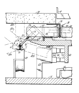
The bogie shown in Fig. 2 is suitable for installa-
tion on a car, such as is shown in Fig. 1, provided
that certain changes in the guideway configuration are
made. More particularly, a guiderail 30 is not disposed
on the base of the guideway 14, but rather is attached
"upside down" to a wall (not illustrated) or beneath
a landing 32 in the guideway. The guiderail 30 is
disposed longitudinally in the guideway 14 and has a
face 34 that is oriented towards the cable 10 and a
face 36 that is oriented away from the cable 10.
Both faces 34,36 are perpendicular to the base of
the guideway 14 and the guiderail has a thickness
associated with the distance between the two faces 34,36.
A rail follower assembly 38 is mounted to a frame
40 which is attached to or part of the frame
of the car 12. A tire 42 and a tire 44 are
journaled to the frame 40,and the clearance between
the tires, in other words, between their peripheries,
- corresponds to the thickness of the guiderail so that
the tires 42,44 snugly cooperate with the guiderail 30
to provide lateral guidance for the car 12, which is
suspended in the guideway 14 by the air-cushion
assembly 16. The tires 42,44 have an O.D. on the order
of fifteen inches. Each tire defines and occupies a
portion of the cross-sectional area of the guideway 14.
The cross-sectional areas of the guideway 14 that are
occupied by the various elements described herein are
significant in the context of packaging a bogie to
occupy the least amount of space, which translates into
guideway width and height savings, without sacrificing
performance.
12~3i/r~ ~5
-6-
In the event of a single or multiple tire failure
lateral guidance for the car 12 would be impaired.
Therefore, a backup guidance system is provided that
comprises two safety rollers 46,48 (shown in phantom),
each of which is journaled to the frame 40. The roller
46 is disposed within the cross-sectional area defined
by the tire 42,and the roller 48 is disposed within
the cross-sectional area defined by the tire 44. The
clearance between the periphery of the rollers 46,48
is greater than the thickness of the guiderail 30, but
not much greater, so that the rollers will provide
lateral guidance to the car 12 in the event of a failure
of the primary guidance system (i.e., the tires). The
lateral play inherent in the backup guidance system must
be taken into account in the design of the guideway to
allow for worst-case clearance between the car 12 and
any obstructions in the guideway 14, and it is preferable
that the play not be sufficient to allow the cable to
jump off of the sheaves.
One of the major consumers of cross-sectional area
in the guideway 14 is the sheaves 22, one of which is
shown in solid lines. The cable 10 rides on the sheaves
22, or pulleys, which provide support for the cable
and also establish a cable path 50 in the guideway.
Since the cable 10 is a closed loop, there is also a
return cable path (not shown), inclusion of which in
the drawing would only obfuscate the teachings herein.
In the general case, the guideway follows a straight and
level course. Therefore, the sheaves are disposed as
shown by the solid-lined sheave 22. However, other
cases are possible. For instance, the guideway may
veer toward the cable. In that case, the sheave must
31235
be oriented so as to provide lateral, as well as vertical
support for the cable, and is thus shown as the phantom
sheave 22A. In another case, the guideway veers away
from the cable and the sheave must be oriented as shown
by the phantom sheave 22B. The guideway may also crest a
hill, in which case the sheave would be oriented in its
normal position (22). In another case the guideway dips,
and it is necessary to provide downward vertical support
on the cable, and the sheave must be oriented vertically,
above the cable 10, as shown by the phantom sheave 22C.
Furthermore, the guideway may simultaneously be cresting
a hill and turning, in which case the sheave would be in
a configuration as shown by the phantom sheaves 22A, 22B
or in any of the configurations included therebetween
(not shown). However, when the guideway dips, it is
permissible only that it be turning towards the cable,
which would require a sheave 22D. A dipping turn away
from the cable would require a sheave to be oriented in
the space occupied by the tire 42 and other bogie
elements as discussed hereinafter. This design
limitation must be accounted for in the planning and
layout of a guideway. Therefore, there exists a range
of permissible sheave configurations between the sheave
22B and clockwise (as shown) through to the sheave 22C
which define a cross-sectional area of the guideway
which, since the sheaves are fixed to the guideway 14, is
not available to be occupied by any of the apparatus
associated with the moving car 12.
A cable clamp 54 attaches the cable lO to the car
12. The cable clamp must be large, on the order of three
to four inches in each dimension, to accommodate the
driving force imparted by the cable 10 to the car 12.
Since the cable clamp 54 is large, the cable 10 must be
displaced from the cable path 50, in other words,
~Z~312~S
-8-
from its normal position in the sheaves 22 to be
clamped by the cable clamp 54. Otherwise, the clamp
54 would imping~ on the sheave 22, 22A, 22B, 22C or
22D. Stated succinctly, the cross-sectional area
occupied by the clamp 54 cannot coincide with the
cross-sectional area occupied by the range of sheave
configurations.
The top view of Fig. 3 provides another perspective
of this situation. Therein it may be seen that the
cable clamp 54 displaces the cable 10 from the cable
path 50 and, in fact, lifts the cable 10 entirely off
of the nearby sheave 22. This displacement defines an
offset cable path 55, the cross-sectional area of which,
in relation to the quideway 14, is best seen in Fig. 2.
But, continuing with the discussion of Fig. 3, it is
easily seen that the large displacement involved in
attaching the cable 10 to the car would quickly derail
the cable 10 from the sheaves 22 without additional
measures. Therefore, cable supports 56,56 are provided
both foreward and rearward of the cable clamp 54 to
pick up the cable from a sheave and replace the cable
back onto a sheave as the car moves past the sheaves
in the guideway. Since a cablesupport 56 carries no
load other than any tension induced by the displacement
of the cable 10, a cable support 56 may simply be a thin
strap 58 at the end of an arm 60. As a matter of fact,
the tension of the displaced cable will tend to hold the
cable in the arm 60 and the strap 58 is provided merely to
retain the cable 10 in the arm 60 in the event that there
is a loss of tension in the cable 10. Therefore the cable
support 56 is small and displaces the cable 10 only a
small amount from the cable oath 50. Whereas the
cable supports 56
23~
g
are shown disposed in close proximity to the rail
followers 38,38, this is simply a matter of manufacturing
convenience,and the cable supports 56 may be located
anywhere along the frame 40 so long as their foreward
and rearward relationship to the cable clamp 54 is
maintained.
More significant aspects of the cable supports
are described with reference to Fig. 2. The ultimate
location of the cable-engaging end of the arm 60
determines the small displacement 61 of the cable 10
from its path 50. Since the strap 58 and the arm 60
are small, the displacement 61 can be correspondingly
small, and varies slightly from sheave configuration
to sheave configuration. Again, nonimpingement of the
cable support 56 with the sheaves is essential. There-
fore, the cross-sectional area occupied by the cable
support 56 cannot be coincident with the cross-sectional
area defined by the ran~e of sheave configurations.
This is most conveniently achieved by taking advantage
of the fact that the offset cable path 55 defines and
occupies a portion of the cross-sectional area of the
guideway, and disposing the arm 60, or at least a
significant portion thereof, within the cross-sectional
area defined by the offset cable path 55. A portion of
the arm 60 could also be disposed within the cross
sectional area defined by the tire 42.
Since guideway space, i.e., cross-sectional area,
is at a premium, it is important to package the various
elements of the bogie in as small a space as possible.
Therefore, the cable clamp 54 is located so that it
occupies substantially the same cross sectional area
that is already occupied by the tire 42 on the cable
side of the rail.
~Z8~Z~
-- 10 --
Another key feature of this invention is the high
location o~ the guiderail 30 and the rail follower
assembl~ 38 which provides additional roll stability
for the car. The location of major guideway space-
consuming elements within coincidental cross-sectional
areas of the guideway, and providing for a maximum
range of sheave configurations is also achieved by
this invention.
It is necessary in the case of blowers for the
hover pad 16 and in any case for car lighting and
other electrical functions within the car 12 to
provide power to the car 12. Therefore, a set of
power rails 64 are mounted via standoff insulators 66
to a bracket 68 that is mounted to the guideway 14.
Power collectors 70 are provided on the car 10 and may
be mounted as shown to the frame 40 and in proximity to
the rail follower assembly 30 in order to receive power
from the power rails 64. Communication may also occur
over the power rails 64 in a manner known to the art.
Other functions, such as position sensing, may be
provided by a module 72 attached to the bracket 68
and a module 74 attached to the frame 40, which modules
72,74 are positioned to cooperate with each other.
The foregoing description of this invention is
intended to enable those skilled in the art to practice
the invention. Various other embodiments and modifica-
tions as are suited to the particular use contemplated
will become apparent upon examination and practice of the
invention .
~;~hat is claimed is: