Language selection

Search

Patent 1281310 Summary

Third-party information liability

Some of the information on this Web page has been provided by external sources. The Government of Canada is not responsible for the accuracy, reliability or currency of the information supplied by external sources. Users wishing to rely upon this information should consult directly with the source of the information. Content provided by external sources is not subject to official languages, privacy and accessibility requirements.

Claims and Abstract availability

Any discrepancies in the text and image of the Claims and Abstract are due to differing posting times. Text of the Claims and Abstract are posted:

  • At the time the application is open to public inspection;
  • At the time of issue of the patent (grant).
(12) Patent: (11) CA 1281310
(21) Application Number: 1281310
(54) English Title: ATTACHMENT TO STABILIZE AND EXPAND THE USE OF LADDERS CONSTRUCTED WITH HOLLOW RUNGS
(54) French Title: ACCESSOIRE POUR STABILISER UNE ECHELLE A ECHELONS CREUX, ET POUR RENDRE CETTE ECHELLE POLYVALENTE
Status: Expired and beyond the Period of Reversal
Bibliographic Data
Abstracts

English Abstract


ATTACHMENTS TO STABILIZE AND EXPAND
THE USE OF HOLLOW RUNG LADDERS
ABSTRACT OF THE DISCLOSURE
A pair of attachments for use with ladders constructed with
hollow rungs to stabilize the ladder and to protect the gutter.
These attachments when used with ladders also provide for a
scaffold plank. The attachments when used with a ladder on a
pitched roof allows the ladder to be used to access that roofs
peak. Previously the ladder would rest on the rain gutter when the
user was to access the roof of a building. Previously a work
platform had to be built from wood or metal resulting in time
consuming construction. Previously when accessing the roof peak
of a building a means of providing a positive foothold had to be
constructed from rope and ladder or from wood. The present invention
provides steel flat bars bent to fit the rung spacing of the ladder
with a steel tube welded at each end sized to fit snuggly into the
opening of any two consecutive rungs in that ladder. The ladder can
now be used to access the roof of a building without resting on the
gutter. The ladder can be used as part of a scaffold and to
provide a positive foothold when on a pitched roof.


Claims

Note: Claims are shown in the official language in which they were submitted.

THE EMBODIMENTS OF THE INVENTION IN WHICH
ARE EXCLUSIVE PROPERTY OR PRIVILEGE IS
CLAIMED ARE DEFINED AS FOLLOWS:
1. A bracket attachment for a ladder having a plurality of
spaced hollow rungs, said bracket attachment having a flat
metal bar bended at an angle, a pair of metal tubes, each one
of said metal tubes being attached at one end to each end of said
flat metal bar, the other end of said metal tubes extending a
distance from an edge of said flat metal bar, the opposite
distance between each metal tube being greater than the distance
between a pair of adjacent hollow rungs whereby upon compression
of each end of said flat metal bar toward each other, the metal
tubes could be inserted into the hollow rungs of the ladder with
a spring action providing a positive locking of said bracket
within the ladder rungs and without the use of any other fastening
means.
*************

Description

Note: Descriptions are shown in the official language in which they were submitted.


~2~3~3~ 0
ATTACHL~T TO STABILI~ AM~ EXP~
T~E USE OF HOLL~^I R~NC. LA~rERS
EACKGRDU~D OF I~E I~ ~ION
The invention relates to the field of ladders and scaffolds.
Mbre particularly, the invention relates to expanding the use
of a ladder. Ladders are used extensively in ard about the home and
ir.dustry. Many users for example use the ladder to access the roof of
a building. The ladder is also used to gain access to the side of a
building. Currently when the ladder is used to access the roof of that
building it in many cases must rest on the rain gutter. Currentl~
~Jhen on the roof ~te user usually relies on his foot wear for his
footing. Currently when a platfcLm is required for a work project
it must be fabricated from material brought into the wor~ area in
place of the ladder already present.
The ladder related to this invention is a ladder fahricated frc~.t
aluminum with holl~^r rungs. It is apparent that ~Ihen the ladder is
rested on the light weight aluminu~ or ~inyl gutter, that rain
gutter presents both a smooth surface for which the ladder to slide
off as ~rell as weak oonstruction for support of the ladder and its
a load. ~^~ten working on a pitc~ned roof the surface ma~ be slippery due
to sno~, ice or rain. It may afford poor footing by virtue of its
steep pitch or construction material. Many jobs are attempted from
a poor platform because the building of a suitable platform is
considered to large a task for tne job at hand. Many people have
fallen with ladders tmsecured, from roofs affording poor footing
and from make-shift platform, to serious injury. me problem is
p æticularly prominent æound the home wtere the user is un~^7are
of the dangers involved with the use of a ladder and where ln many
cases safety is left to chance for lack of a convenient safety device.
3C
.

~L~8~:~10
SUM~gY OF INVENTION
The present invention provides for a set of attachements to
fit into the ladder all~ing part of the load placed o~ the
ladder to be transfered to the roof over the gutter thus protecting
the gutter and stabilizing the ladder. Ihe present invention
allows the ladder to bec~me part of a scaffold. The present
invention allcws the ladder to be used as a positive foothold when on
the pitched roof of a building. It comprises a set of flatbars
bent through a radius to an angle with tubing welded at right
angles at either end allowing these brackets to fit into ladders
with hollow rungs.
q

lZ~3~
BRIEF ~ESCRIPTION OF TIIE D~ r,~IMGS
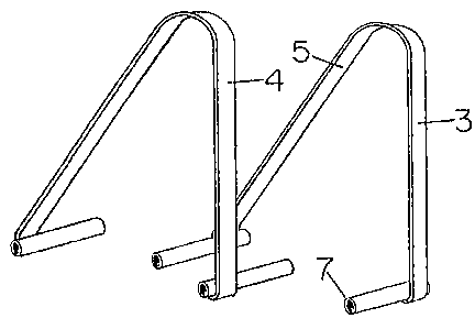
Fig. 1 is a perspective view of ~y invention showing the
ccmponents of the invention.
Fig. 2 is a perspective view of ~le ladder showing my
invention in place to stabilize the lad~er on the roof over and
away from the gutter.
Fig. 3 is a perspective view of the ladder showing my invention
in place over the roof peak and all~ring the ladders to become
part of a scaffold.
Fig. 4 and 5 are a perspective view of two folding ladders with
my invention in plaoe supporting part of a scaffold.
Referring specifically to the drawings in which like numerals refer
to like parts, numeral 1 is a conventional ladder with hollow rungs
; Detachably connected with any of the ladder having a ~etal tubing7 welded at a right angle to each end of the bar 5. The metal tubing
7 having a diameter less that the insider diameter of the hollow
rungs 2. The brackets 3 and 4 are mirror image of each other.
The length 8 of one leg of the flat bar 5 differs frcm the
length 9 of the other leg to all~r for various use of the device.
e distance "~" between the metal tubing 7 or each bracket
is greater than the distance bet~een a pair of adjacent hollow
rungs 2.
The problem with designing an attac~ ent of this nature is
designing it free of moving parts to fit all ladders with hollcw
rungs while performing all the embodl~ints depicted by the
accomDanying illustrations. The present invention does, however,
perform all the embodiments illustrated herein.
In operation the attendant will grasp each of the two pieces
of the attachment at the welded ends and spring them sliahtly. This
will allow for a snug fit of the metal tubing into each opposite
ends of a pair of hollow run~f the ladder at the desired loca-tion.
As well be apparent to persons skilled in the art, various
modifications and adaptions of the structure above-described are
possible without de~arture fram the spirit of ~he invention. The
scope of which is defined in the appended claims.
.~

Representative Drawing
A single figure which represents the drawing illustrating the invention.
Administrative Status

2024-08-01:As part of the Next Generation Patents (NGP) transition, the Canadian Patents Database (CPD) now contains a more detailed Event History, which replicates the Event Log of our new back-office solution.

Please note that "Inactive:" events refers to events no longer in use in our new back-office solution.

For a clearer understanding of the status of the application/patent presented on this page, the site Disclaimer , as well as the definitions for Patent , Event History , Maintenance Fee  and Payment History  should be consulted.

Event History

Description Date
Inactive: IPC from MCD 2006-03-11
Time Limit for Reversal Expired 2005-03-14
Inactive: Adhoc Request Documented 2004-12-15
Inactive: Payment - Insufficient fee 2004-04-06
Letter Sent 2004-03-12
Inactive: Office letter 2000-11-02
Inactive: Office letter 2000-08-23
Change of Address Requirements Determined Compliant 2000-08-22
Inactive: Late MF processed 2000-08-03
Letter Sent 2000-03-13
Grant by Issuance 1991-03-12

Abandonment History

There is no abandonment history.

Fee History

Fee Type Anniversary Year Due Date Paid Date
MF (category 1, 7th anniv.) - small 1998-03-12 1998-03-05
MF (category 1, 8th anniv.) - small 1999-03-12 1999-03-12
MF (category 1, 10th anniv.) - small 2001-03-12 2000-08-03
Reversal of deemed expiry 2000-03-13 2000-08-03
MF (category 1, 9th anniv.) - small 2000-03-13 2000-08-03
MF (category 1, 11th anniv.) - small 2002-03-12 2002-01-30
MF (category 1, 12th anniv.) - small 2003-03-12 2003-02-25
Owners on Record

Note: Records showing the ownership history in alphabetical order.

Current Owners on Record
WAYNE FREDERICK DWINNELL
Past Owners on Record
None
Past Owners that do not appear in the "Owners on Record" listing will appear in other documentation within the application.
Documents

To view selected files, please enter reCAPTCHA code :


To view images, click a link in the Document Description column. To download the documents, select one or more checkboxes in the first column and then click the "Download Selected in PDF format (Zip Archive)" or the "Download Selected as Single PDF" button.

List of published and non-published patent-specific documents on the CPD .

If you have any difficulty accessing content, you can call the Client Service Centre at 1-866-997-1936 or send them an e-mail at CIPO Client Service Centre.


Document
Description 
Date
(yyyy-mm-dd) 
Number of pages   Size of Image (KB) 
Claims 1993-10-19 1 23
Cover Page 1993-10-19 1 12
Abstract 1993-10-19 1 31
Drawings 1993-10-19 1 32
Descriptions 1993-10-19 3 102
Representative drawing 2002-01-03 1 8
Notice: Maintenance Fee Reminder 1997-12-15 1 119
Notice: Maintenance Fee Reminder 1998-12-15 1 118
Notice: Maintenance Fee Reminder 1999-12-14 1 119
Maintenance Fee Notice 2000-04-10 1 178
Late Payment Acknowledgement 2000-08-22 1 171
Notice: Maintenance Fee Reminder 2001-12-13 1 120
Notice: Maintenance Fee Reminder 2002-12-16 1 115
Notice: Maintenance Fee Reminder 2003-12-15 1 125
Notice of Insufficient fee payment (English) 2004-04-06 1 92
Maintenance Fee Notice 2004-08-02 1 172
Second Notice: Maintenance Fee Reminder 2004-09-14 1 122
Notice: Maintenance Fee Reminder 2004-12-14 1 118
Fees 2003-02-25 2 65
Fees 1999-03-17 2 105
Fees 2002-01-30 1 21
Fees 1998-03-05 2 108
Fees 2000-08-03 2 59
Fees 2000-10-20 2 56
Fees 2004-03-11 2 44
Fees 1997-03-10 2 137
Fees 1996-02-13 2 152
Correspondence 1996-01-08 1 22
Fees 1995-12-12 2 165
Fees 1995-01-31 1 88
Fees 1994-04-06 1 69
Fees 1994-08-10 2 91
Fees 1992-10-13 1 71
Fees 1994-03-11 4 415
Correspondence 1994-04-13 1 15