Sélection de la langue

Search

Sommaire du brevet 1281310 

Énoncé de désistement de responsabilité concernant l'information provenant de tiers

Une partie des informations de ce site Web a été fournie par des sources externes. Le gouvernement du Canada n'assume aucune responsabilité concernant la précision, l'actualité ou la fiabilité des informations fournies par les sources externes. Les utilisateurs qui désirent employer cette information devraient consulter directement la source des informations. Le contenu fourni par les sources externes n'est pas assujetti aux exigences sur les langues officielles, la protection des renseignements personnels et l'accessibilité.

Disponibilité de l'Abrégé et des Revendications

L'apparition de différences dans le texte et l'image des Revendications et de l'Abrégé dépend du moment auquel le document est publié. Les textes des Revendications et de l'Abrégé sont affichés :

  • lorsque la demande peut être examinée par le public;
  • lorsque le brevet est émis (délivrance).
(12) Brevet: (11) CA 1281310
(21) Numéro de la demande: 1281310
(54) Titre français: ACCESSOIRE POUR STABILISER UNE ECHELLE A ECHELONS CREUX, ET POUR RENDRE CETTE ECHELLE POLYVALENTE
(54) Titre anglais: ATTACHMENT TO STABILIZE AND EXPAND THE USE OF LADDERS CONSTRUCTED WITH HOLLOW RUNGS
Statut: Périmé et au-delà du délai pour l’annulation
Données bibliographiques
Abrégés

Abrégé anglais


ATTACHMENTS TO STABILIZE AND EXPAND
THE USE OF HOLLOW RUNG LADDERS
ABSTRACT OF THE DISCLOSURE
A pair of attachments for use with ladders constructed with
hollow rungs to stabilize the ladder and to protect the gutter.
These attachments when used with ladders also provide for a
scaffold plank. The attachments when used with a ladder on a
pitched roof allows the ladder to be used to access that roofs
peak. Previously the ladder would rest on the rain gutter when the
user was to access the roof of a building. Previously a work
platform had to be built from wood or metal resulting in time
consuming construction. Previously when accessing the roof peak
of a building a means of providing a positive foothold had to be
constructed from rope and ladder or from wood. The present invention
provides steel flat bars bent to fit the rung spacing of the ladder
with a steel tube welded at each end sized to fit snuggly into the
opening of any two consecutive rungs in that ladder. The ladder can
now be used to access the roof of a building without resting on the
gutter. The ladder can be used as part of a scaffold and to
provide a positive foothold when on a pitched roof.

Revendications

Note : Les revendications sont présentées dans la langue officielle dans laquelle elles ont été soumises.


THE EMBODIMENTS OF THE INVENTION IN WHICH
ARE EXCLUSIVE PROPERTY OR PRIVILEGE IS
CLAIMED ARE DEFINED AS FOLLOWS:
1. A bracket attachment for a ladder having a plurality of
spaced hollow rungs, said bracket attachment having a flat
metal bar bended at an angle, a pair of metal tubes, each one
of said metal tubes being attached at one end to each end of said
flat metal bar, the other end of said metal tubes extending a
distance from an edge of said flat metal bar, the opposite
distance between each metal tube being greater than the distance
between a pair of adjacent hollow rungs whereby upon compression
of each end of said flat metal bar toward each other, the metal
tubes could be inserted into the hollow rungs of the ladder with
a spring action providing a positive locking of said bracket
within the ladder rungs and without the use of any other fastening
means.
*************

Description

Note : Les descriptions sont présentées dans la langue officielle dans laquelle elles ont été soumises.

~2~3~3~ 0
ATTACHL~T TO STABILI~ AM~ EXP~
T~E USE OF HOLL~^I R~NC. LA~rERS
EACKGRDU~D OF I~E I~ ~ION
The invention relates to the field of ladders and scaffolds.
Mbre particularly, the invention relates to expanding the use
of a ladder. Ladders are used extensively in ard about the home and
ir.dustry. Many users for example use the ladder to access the roof of
a building. The ladder is also used to gain access to the side of a
building. Currently when the ladder is used to access the roof of that
building it in many cases must rest on the rain gutter. Currentl~
~Jhen on the roof ~te user usually relies on his foot wear for his
footing. Currently when a platfcLm is required for a work project
it must be fabricated from material brought into the wor~ area in
place of the ladder already present.
The ladder related to this invention is a ladder fahricated frc~.t
aluminum with holl~^r rungs. It is apparent that ~Ihen the ladder is
rested on the light weight aluminu~ or ~inyl gutter, that rain
gutter presents both a smooth surface for which the ladder to slide
off as ~rell as weak oonstruction for support of the ladder and its
a load. ~^~ten working on a pitc~ned roof the surface ma~ be slippery due
to sno~, ice or rain. It may afford poor footing by virtue of its
steep pitch or construction material. Many jobs are attempted from
a poor platform because the building of a suitable platform is
considered to large a task for tne job at hand. Many people have
fallen with ladders tmsecured, from roofs affording poor footing
and from make-shift platform, to serious injury. me problem is
p æticularly prominent æound the home wtere the user is un~^7are
of the dangers involved with the use of a ladder and where ln many
cases safety is left to chance for lack of a convenient safety device.
3C
.

~L~8~:~10
SUM~gY OF INVENTION
The present invention provides for a set of attachements to
fit into the ladder all~ing part of the load placed o~ the
ladder to be transfered to the roof over the gutter thus protecting
the gutter and stabilizing the ladder. Ihe present invention
allows the ladder to bec~me part of a scaffold. The present
invention allcws the ladder to be used as a positive foothold when on
the pitched roof of a building. It comprises a set of flatbars
bent through a radius to an angle with tubing welded at right
angles at either end allowing these brackets to fit into ladders
with hollow rungs.
q

lZ~3~
BRIEF ~ESCRIPTION OF TIIE D~ r,~IMGS
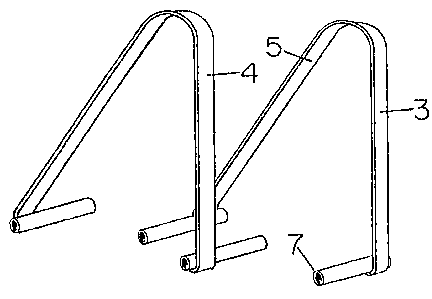
Fig. 1 is a perspective view of ~y invention showing the
ccmponents of the invention.
Fig. 2 is a perspective view of ~le ladder showing my
invention in place to stabilize the lad~er on the roof over and
away from the gutter.
Fig. 3 is a perspective view of the ladder showing my invention
in place over the roof peak and all~ring the ladders to become
part of a scaffold.
Fig. 4 and 5 are a perspective view of two folding ladders with
my invention in plaoe supporting part of a scaffold.
Referring specifically to the drawings in which like numerals refer
to like parts, numeral 1 is a conventional ladder with hollow rungs
; Detachably connected with any of the ladder having a ~etal tubing7 welded at a right angle to each end of the bar 5. The metal tubing
7 having a diameter less that the insider diameter of the hollow
rungs 2. The brackets 3 and 4 are mirror image of each other.
The length 8 of one leg of the flat bar 5 differs frcm the
length 9 of the other leg to all~r for various use of the device.
e distance "~" between the metal tubing 7 or each bracket
is greater than the distance bet~een a pair of adjacent hollow
rungs 2.
The problem with designing an attac~ ent of this nature is
designing it free of moving parts to fit all ladders with hollcw
rungs while performing all the embodl~ints depicted by the
accomDanying illustrations. The present invention does, however,
perform all the embodiments illustrated herein.
In operation the attendant will grasp each of the two pieces
of the attachment at the welded ends and spring them sliahtly. This
will allow for a snug fit of the metal tubing into each opposite
ends of a pair of hollow run~f the ladder at the desired loca-tion.
As well be apparent to persons skilled in the art, various
modifications and adaptions of the structure above-described are
possible without de~arture fram the spirit of ~he invention. The
scope of which is defined in the appended claims.
.~

Dessin représentatif
Une figure unique qui représente un dessin illustrant l'invention.
États administratifs

2024-08-01 : Dans le cadre de la transition vers les Brevets de nouvelle génération (BNG), la base de données sur les brevets canadiens (BDBC) contient désormais un Historique d'événement plus détaillé, qui reproduit le Journal des événements de notre nouvelle solution interne.

Veuillez noter que les événements débutant par « Inactive : » se réfèrent à des événements qui ne sont plus utilisés dans notre nouvelle solution interne.

Pour une meilleure compréhension de l'état de la demande ou brevet qui figure sur cette page, la rubrique Mise en garde , et les descriptions de Brevet , Historique d'événement , Taxes périodiques et Historique des paiements devraient être consultées.

Historique d'événement

Description Date
Inactive : CIB de MCD 2006-03-11
Le délai pour l'annulation est expiré 2005-03-14
Inactive : Demande ad hoc documentée 2004-12-15
Inactive : Paiement - Taxe insuffisante 2004-04-06
Lettre envoyée 2004-03-12
Inactive : Lettre officielle 2000-11-02
Inactive : Lettre officielle 2000-08-23
Exigences pour le changement d'adresse - jugé conforme 2000-08-22
Inactive : TME en retard traitée 2000-08-03
Lettre envoyée 2000-03-13
Accordé par délivrance 1991-03-12

Historique d'abandonnement

Il n'y a pas d'historique d'abandonnement

Historique des taxes

Type de taxes Anniversaire Échéance Date payée
TM (catégorie 1, 7e anniv.) - petite 1998-03-12 1998-03-05
TM (catégorie 1, 8e anniv.) - petite 1999-03-12 1999-03-12
TM (catégorie 1, 10e anniv.) - petite 2001-03-12 2000-08-03
Annulation de la péremption réputée 2000-03-13 2000-08-03
TM (catégorie 1, 9e anniv.) - petite 2000-03-13 2000-08-03
TM (catégorie 1, 11e anniv.) - petite 2002-03-12 2002-01-30
TM (catégorie 1, 12e anniv.) - petite 2003-03-12 2003-02-25
Titulaires au dossier

Les titulaires actuels et antérieures au dossier sont affichés en ordre alphabétique.

Titulaires actuels au dossier
WAYNE FREDERICK DWINNELL
Titulaires antérieures au dossier
S.O.
Les propriétaires antérieurs qui ne figurent pas dans la liste des « Propriétaires au dossier » apparaîtront dans d'autres documents au dossier.
Documents

Pour visionner les fichiers sélectionnés, entrer le code reCAPTCHA :


Pour visualiser une image, cliquer sur un lien dans la colonne description du document. Pour télécharger l'image (les images), cliquer l'une ou plusieurs cases à cocher dans la première colonne et ensuite cliquer sur le bouton "Télécharger sélection en format PDF (archive Zip)" ou le bouton "Télécharger sélection (en un fichier PDF fusionné)".

Liste des documents de brevet publiés et non publiés sur la BDBC .

Si vous avez des difficultés à accéder au contenu, veuillez communiquer avec le Centre de services à la clientèle au 1-866-997-1936, ou envoyer un courriel au Centre de service à la clientèle de l'OPIC.


Description du
Document 
Date
(aaaa-mm-jj) 
Nombre de pages   Taille de l'image (Ko) 
Revendications 1993-10-19 1 23
Page couverture 1993-10-19 1 12
Abrégé 1993-10-19 1 31
Dessins 1993-10-19 1 32
Description 1993-10-19 3 102
Dessin représentatif 2002-01-03 1 8
Avis de rappel: Taxes de maintien 1997-12-15 1 119
Avis de rappel: Taxes de maintien 1998-12-15 1 118
Avis de rappel: Taxes de maintien 1999-12-14 1 119
Avis concernant la taxe de maintien 2000-04-10 1 178
Quittance d'un paiement en retard 2000-08-22 1 171
Avis de rappel: Taxes de maintien 2001-12-13 1 120
Avis de rappel: Taxes de maintien 2002-12-16 1 115
Avis de rappel: Taxes de maintien 2003-12-15 1 125
Avis de paiement insuffisant pour taxe (anglais) 2004-04-06 1 92
Avis concernant la taxe de maintien 2004-08-02 1 172
Deuxième avis de rappel: taxes de maintien 2004-09-14 1 122
Avis de rappel: Taxes de maintien 2004-12-14 1 118
Taxes 2003-02-25 2 65
Taxes 1999-03-17 2 105
Taxes 2002-01-30 1 21
Taxes 1998-03-05 2 108
Taxes 2000-08-03 2 59
Taxes 2000-10-20 2 56
Taxes 2004-03-11 2 44
Taxes 1997-03-10 2 137
Taxes 1996-02-13 2 152
Correspondance 1996-01-08 1 22
Taxes 1995-12-12 2 165
Taxes 1995-01-31 1 88
Taxes 1994-04-06 1 69
Taxes 1994-08-10 2 91
Taxes 1992-10-13 1 71
Taxes 1994-03-11 4 415
Correspondance 1994-04-13 1 15