Language selection

Search

Patent 1282054 Summary

Third-party information liability

Some of the information on this Web page has been provided by external sources. The Government of Canada is not responsible for the accuracy, reliability or currency of the information supplied by external sources. Users wishing to rely upon this information should consult directly with the source of the information. Content provided by external sources is not subject to official languages, privacy and accessibility requirements.

Claims and Abstract availability

Any discrepancies in the text and image of the Claims and Abstract are due to differing posting times. Text of the Claims and Abstract are posted:

  • At the time the application is open to public inspection;
  • At the time of issue of the patent (grant).
(12) Patent: (11) CA 1282054
(21) Application Number: 1282054
(54) English Title: DISC CUTTERS FOR ROCK WORKING MACHINES
(54) French Title: OUTILS DE COUPE A DISQUES POUR FORATION DANS LE ROC
Status: Expired and beyond the Period of Reversal
Bibliographic Data
(51) International Patent Classification (IPC):
  • E21B 10/00 (2006.01)
  • E21B 10/12 (2006.01)
  • E21D 09/10 (2006.01)
(72) Inventors :
  • LAMBSON, ROGER STEPHEN (South Africa)
  • POPE, NOEL CUTHBERT (South Africa)
  • GRIFFITHS, VAUGHAN (South Africa)
(73) Owners :
  • BOART INTERNATIONAL LIMITED
(71) Applicants :
  • BOART INTERNATIONAL LIMITED (South Africa)
(74) Agent: KIRBY EADES GALE BAKER
(74) Associate agent:
(45) Issued: 1991-03-26
(22) Filed Date: 1987-01-27
Availability of licence: N/A
Dedicated to the Public: N/A
(25) Language of filing: English

Patent Cooperation Treaty (PCT): No

(30) Application Priority Data:
Application No. Country/Territory Date
86/0627 (South Africa) 1986-01-28

Abstracts

English Abstract


ABSTRACT
A hardmetal ring is a size for size or low interference fit on the
body of a disc cutter of a rock working machine, such as a boxhole
borer, In one embodiment the ring is gable shaped and clamped
between a fixed annular shoulder and a detachable annular shoulder.
In another embodiment the ring is triangular in section and two
annular shoulders resting on it and inclined surfaces on the body
clamp the ring to the body.


Claims

Note: Claims are shown in the official language in which they were submitted.

THE EMBODIMENTS OF THE INVENTION IN WHICH AN EXCLUSIVE
PROPERTY OR PRIVILEGE IS CLAIMED ARE DEFINED AS FOLLOWS:
1.
A disc cutter for a rock working machine comprising a body journalled for rotation
about a shaft adapted to be secured to the machine and a continuously annular
non-segmented cutting ring which is secured to the body characterized in that the
cutting ring comprises hardmetal, and defines a continuous uninterrupted, annular
cutting edge of hardmetal, the cutting ring is a size for size fit or a low interference
fit on the body, is mounted on the body without tensile hoop stress, and is held on
the body by two flanking annular shoulders without exerting any radially outwardforces on the cutting ring, and at least one of the shoulders is detachable.
2.
The disc cutter claimed in claim 1 in which the cutting ring is gable shaped in
section with two parallel faces radiating from the body and the ring is flanked by
a fixed shoulder and a detachable shoulder.
3.
The disc cutter claimed in claim 1 in which the cutting ring is triangular in section
and is flanked by two shoulders detachably secured to inclined faces on the bodyand resting against the inclined faces of the ring.

Description

Note: Descriptions are shown in the official language in which they were submitted.


~2820~
-2-
BACKGROUND TO THE INVENTION
_
This invention relates to disc cutters for rock working machines such
as raise borers and boxhole borers.
Conventional disc cutting machines of the type in question have disc
cutters which compr;se a body journalled for rotation about a shaft
secured to the rock working machine. On the body there is a stee1
cutting ring which is secured with a high interference fit as by heat
shrinking. When hard abrasive rock has to be worked, the steel rings
on conventional cutting discs blunt very quickly so that rock working
10 machines with cutting discs become uneconomical to use.
:: .
It has therefore been proposed to replace the steel cuttlng edge ln
such a disc with hardmeta1 such as cobalt cemented tungsten carbide or
titanlum carbide. The earllest proposals in this regard dealt with the
fixing of segments of hardmetal on the body - see US patents Nos.
15 3 981 370 and 3 982 59~. These proposals did not, however, come into
practical use, probably because of failures at the abutting faces of
the segments.
. , ~
.
- '
::
~ .

3L2~
--3--
In US patent No. 3 766 998 the use of a continuous ring of hardmetal is
proposed. The ring is lozenge shaped in cross-section and is clamped
between inclined faces which exert a radially outward hoop stress. The
patent cautions against applying too much tensile stress to the ring,
5 but it advocates the use of some amount of tensile stress to start
with. This proposal has also not been commercialised and the applicant
believes that such a ring would fail In use due to the cumulative
effects of the initial hoop s~ress and hoop stresses caused by the
cutting loads. The geometry of the ring support does not have
10 sufficient stiffness to provide adequate support to the ring. The
- induced tensile hoop stresses in the lower portion of the profile due
to cutting loads superimposed on the tensile hoop stresses due to
fitting will cause the ring to break.
SUMMARY ~f THE INVENTION
. ~ . _
15 According to the invention a cutting ring of hardmetal is a size for
size fit or a low interference fit on the body, is held on the body by
two flanking annular shoulders without exerting any radially outward
forces on the cutting ring, and at least one of the shoulders is
detachable.
20 In one form of the invention the cutting ring is gable shaped in
section with two parallel faces radiating from the body and the ring is
flanked by a fixed shoulder and a detachable shoulder.
In another form of the invention the ring is triangular in section and
is flanked by two shoulders detachably secured to inclined faces on the
25 body and resting against the inclined faces of the ring.

~32C~
--4--
DESCRIPTION OF THE DRAWINGS
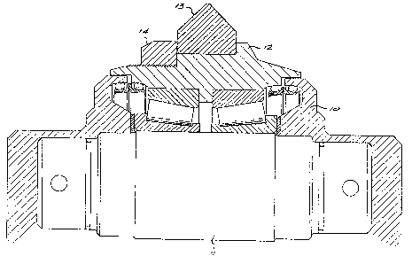
Figure 1 is a part section through one embodiment of the invention; and
Figure 2 is a similar view of another embodiment.
DESCRIPTION OF EMBODIMENTS
'; '
5 In each of the embodiments a body 10 is ~journalled to a shaft 11 by
means of suitable roller bearings in a conventional manner.
In the embodiment of Figure 1 the ~ody 10 is formed with a fixed
shoulder 12. Against the shoulder there rests a gable-section cutting
ring 13 made of cemented tungsten carbide. Circumferentially the ring
10 13 is a locational fit on the body 10. A detachable annular shoulder
14 is screwed on to the body 10.
, . . .
In Figure 2 there is a cutting r;ng 15 which ;s triangular in section.
The ring 15 is a locational fit on the body 10. On each side of the
ring 15 there is an annular clamping ring 16 attached to inclined faces
~; lS on the body 10 by means of cap screws. The purpose of the clamping
rings 16 is to introduce residual compressive stresses into the
hardmetal ring lS while locating it in position. ~rass shims 17 are
interposed between the rings 16 and 15 to ensure uniform compression.
'
~: In each embodiment the ring 13 or 15 is securely held against sideways
20 movement. The rings are readily resharpenable.
.~ -
Laboratory tests have shown that for a given penetration the cutting
forces for the hardmetal cutter of Figure 1 are essent;ally the same as
those for a sharp steel disc cutter in norite. However a blunt steel
disc cutter produced only half the penetration of the hardmetal cutter
25 for a given force. This is illustrated by the following table:-
.; ''
.
:

2~
- 5 -
~, ~
Sharp Steel I Blunt Steel I Hardmetal
Thrust IRolling I Thrust jRolling I Thrust IRolling
Force IForce ! Force IForce I Force IForce
5 Penetration (2mm)l 141 kN I 8,3 kN I 194 kN 110.7 kN I 153 kN I 7,7 kN
Penetration (4mm)l 188 kN 117,7 kN I 271 kN 117,7 kN I 191 kN l13,8_kN
~
A partial field test using six disc cutters according to F;g,ure 1 on a
Robbins boxhole borer was conducted. The other seven cutters had
conventional steel cutting rings. A hole 55 m long was bored. The steel
10 cutting rings had to be replaced at 31 m and at the end of the 55 m bore the
steel rings required replacement once more. On the other hand the six
hardmetal rings were intact and from wear measurements made, it was predicted
~-~ that the hardmetal rings would each have a cutting li~e of 400 m. Under the
same conditions stee1 rings have an averdge life of 25 m.
.

Representative Drawing
A single figure which represents the drawing illustrating the invention.
Administrative Status

2024-08-01:As part of the Next Generation Patents (NGP) transition, the Canadian Patents Database (CPD) now contains a more detailed Event History, which replicates the Event Log of our new back-office solution.

Please note that "Inactive:" events refers to events no longer in use in our new back-office solution.

For a clearer understanding of the status of the application/patent presented on this page, the site Disclaimer , as well as the definitions for Patent , Event History , Maintenance Fee  and Payment History  should be consulted.

Event History

Description Date
Inactive: IPC from MCD 2006-03-11
Time Limit for Reversal Expired 2000-03-27
Letter Sent 1999-03-26
Grant by Issuance 1991-03-26

Abandonment History

There is no abandonment history.

Fee History

Fee Type Anniversary Year Due Date Paid Date
MF (category 1, 7th anniv.) - standard 1998-03-26 1998-02-26
Owners on Record

Note: Records showing the ownership history in alphabetical order.

Current Owners on Record
BOART INTERNATIONAL LIMITED
Past Owners on Record
NOEL CUTHBERT POPE
ROGER STEPHEN LAMBSON
VAUGHAN GRIFFITHS
Past Owners that do not appear in the "Owners on Record" listing will appear in other documentation within the application.
Documents

To view selected files, please enter reCAPTCHA code :


To view images, click a link in the Document Description column. To download the documents, select one or more checkboxes in the first column and then click the "Download Selected in PDF format (Zip Archive)" or the "Download Selected as Single PDF" button.

List of published and non-published patent-specific documents on the CPD .

If you have any difficulty accessing content, you can call the Client Service Centre at 1-866-997-1936 or send them an e-mail at CIPO Client Service Centre.


Document
Description 
Date
(yyyy-mm-dd) 
Number of pages   Size of Image (KB) 
Abstract 1993-10-18 1 14
Claims 1993-10-18 1 31
Drawings 1993-10-18 2 68
Descriptions 1993-10-18 4 111
Representative drawing 2002-01-03 1 22
Maintenance Fee Notice 1999-04-25 1 179
Fees 1997-02-20 1 46
Fees 1996-02-25 1 46
Fees 1995-02-16 1 78
Fees 1994-01-23 1 48
Fees 1993-03-16 1 38