Sélection de la langue

Search

Sommaire du brevet 1282054 

Énoncé de désistement de responsabilité concernant l'information provenant de tiers

Une partie des informations de ce site Web a été fournie par des sources externes. Le gouvernement du Canada n'assume aucune responsabilité concernant la précision, l'actualité ou la fiabilité des informations fournies par les sources externes. Les utilisateurs qui désirent employer cette information devraient consulter directement la source des informations. Le contenu fourni par les sources externes n'est pas assujetti aux exigences sur les langues officielles, la protection des renseignements personnels et l'accessibilité.

Disponibilité de l'Abrégé et des Revendications

L'apparition de différences dans le texte et l'image des Revendications et de l'Abrégé dépend du moment auquel le document est publié. Les textes des Revendications et de l'Abrégé sont affichés :

  • lorsque la demande peut être examinée par le public;
  • lorsque le brevet est émis (délivrance).
(12) Brevet: (11) CA 1282054
(21) Numéro de la demande: 1282054
(54) Titre français: OUTILS DE COUPE A DISQUES POUR FORATION DANS LE ROC
(54) Titre anglais: DISC CUTTERS FOR ROCK WORKING MACHINES
Statut: Périmé et au-delà du délai pour l’annulation
Données bibliographiques
(51) Classification internationale des brevets (CIB):
  • E21B 10/00 (2006.01)
  • E21B 10/12 (2006.01)
  • E21D 09/10 (2006.01)
(72) Inventeurs :
  • LAMBSON, ROGER STEPHEN (Afrique du Sud)
  • POPE, NOEL CUTHBERT (Afrique du Sud)
  • GRIFFITHS, VAUGHAN (Afrique du Sud)
(73) Titulaires :
  • BOART INTERNATIONAL LIMITED
(71) Demandeurs :
  • BOART INTERNATIONAL LIMITED (Afrique du Sud)
(74) Agent: KIRBY EADES GALE BAKER
(74) Co-agent:
(45) Délivré: 1991-03-26
(22) Date de dépôt: 1987-01-27
Licence disponible: S.O.
Cédé au domaine public: S.O.
(25) Langue des documents déposés: Anglais

Traité de coopération en matière de brevets (PCT): Non

(30) Données de priorité de la demande:
Numéro de la demande Pays / territoire Date
86/0627 (Afrique du Sud) 1986-01-28

Abrégés

Abrégé anglais


ABSTRACT
A hardmetal ring is a size for size or low interference fit on the
body of a disc cutter of a rock working machine, such as a boxhole
borer, In one embodiment the ring is gable shaped and clamped
between a fixed annular shoulder and a detachable annular shoulder.
In another embodiment the ring is triangular in section and two
annular shoulders resting on it and inclined surfaces on the body
clamp the ring to the body.

Revendications

Note : Les revendications sont présentées dans la langue officielle dans laquelle elles ont été soumises.


THE EMBODIMENTS OF THE INVENTION IN WHICH AN EXCLUSIVE
PROPERTY OR PRIVILEGE IS CLAIMED ARE DEFINED AS FOLLOWS:
1.
A disc cutter for a rock working machine comprising a body journalled for rotation
about a shaft adapted to be secured to the machine and a continuously annular
non-segmented cutting ring which is secured to the body characterized in that the
cutting ring comprises hardmetal, and defines a continuous uninterrupted, annular
cutting edge of hardmetal, the cutting ring is a size for size fit or a low interference
fit on the body, is mounted on the body without tensile hoop stress, and is held on
the body by two flanking annular shoulders without exerting any radially outwardforces on the cutting ring, and at least one of the shoulders is detachable.
2.
The disc cutter claimed in claim 1 in which the cutting ring is gable shaped in
section with two parallel faces radiating from the body and the ring is flanked by
a fixed shoulder and a detachable shoulder.
3.
The disc cutter claimed in claim 1 in which the cutting ring is triangular in section
and is flanked by two shoulders detachably secured to inclined faces on the bodyand resting against the inclined faces of the ring.

Description

Note : Les descriptions sont présentées dans la langue officielle dans laquelle elles ont été soumises.

~2820~
-2-
BACKGROUND TO THE INVENTION
_
This invention relates to disc cutters for rock working machines such
as raise borers and boxhole borers.
Conventional disc cutting machines of the type in question have disc
cutters which compr;se a body journalled for rotation about a shaft
secured to the rock working machine. On the body there is a stee1
cutting ring which is secured with a high interference fit as by heat
shrinking. When hard abrasive rock has to be worked, the steel rings
on conventional cutting discs blunt very quickly so that rock working
10 machines with cutting discs become uneconomical to use.
:: .
It has therefore been proposed to replace the steel cuttlng edge ln
such a disc with hardmeta1 such as cobalt cemented tungsten carbide or
titanlum carbide. The earllest proposals in this regard dealt with the
fixing of segments of hardmetal on the body - see US patents Nos.
15 3 981 370 and 3 982 59~. These proposals did not, however, come into
practical use, probably because of failures at the abutting faces of
the segments.
. , ~
.
- '
::
~ .

3L2~
--3--
In US patent No. 3 766 998 the use of a continuous ring of hardmetal is
proposed. The ring is lozenge shaped in cross-section and is clamped
between inclined faces which exert a radially outward hoop stress. The
patent cautions against applying too much tensile stress to the ring,
5 but it advocates the use of some amount of tensile stress to start
with. This proposal has also not been commercialised and the applicant
believes that such a ring would fail In use due to the cumulative
effects of the initial hoop s~ress and hoop stresses caused by the
cutting loads. The geometry of the ring support does not have
10 sufficient stiffness to provide adequate support to the ring. The
- induced tensile hoop stresses in the lower portion of the profile due
to cutting loads superimposed on the tensile hoop stresses due to
fitting will cause the ring to break.
SUMMARY ~f THE INVENTION
. ~ . _
15 According to the invention a cutting ring of hardmetal is a size for
size fit or a low interference fit on the body, is held on the body by
two flanking annular shoulders without exerting any radially outward
forces on the cutting ring, and at least one of the shoulders is
detachable.
20 In one form of the invention the cutting ring is gable shaped in
section with two parallel faces radiating from the body and the ring is
flanked by a fixed shoulder and a detachable shoulder.
In another form of the invention the ring is triangular in section and
is flanked by two shoulders detachably secured to inclined faces on the
25 body and resting against the inclined faces of the ring.

~32C~
--4--
DESCRIPTION OF THE DRAWINGS
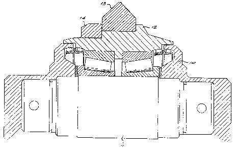
Figure 1 is a part section through one embodiment of the invention; and
Figure 2 is a similar view of another embodiment.
DESCRIPTION OF EMBODIMENTS
'; '
5 In each of the embodiments a body 10 is ~journalled to a shaft 11 by
means of suitable roller bearings in a conventional manner.
In the embodiment of Figure 1 the ~ody 10 is formed with a fixed
shoulder 12. Against the shoulder there rests a gable-section cutting
ring 13 made of cemented tungsten carbide. Circumferentially the ring
10 13 is a locational fit on the body 10. A detachable annular shoulder
14 is screwed on to the body 10.
, . . .
In Figure 2 there is a cutting r;ng 15 which ;s triangular in section.
The ring 15 is a locational fit on the body 10. On each side of the
ring 15 there is an annular clamping ring 16 attached to inclined faces
~; lS on the body 10 by means of cap screws. The purpose of the clamping
rings 16 is to introduce residual compressive stresses into the
hardmetal ring lS while locating it in position. ~rass shims 17 are
interposed between the rings 16 and 15 to ensure uniform compression.
'
~: In each embodiment the ring 13 or 15 is securely held against sideways
20 movement. The rings are readily resharpenable.
.~ -
Laboratory tests have shown that for a given penetration the cutting
forces for the hardmetal cutter of Figure 1 are essent;ally the same as
those for a sharp steel disc cutter in norite. However a blunt steel
disc cutter produced only half the penetration of the hardmetal cutter
25 for a given force. This is illustrated by the following table:-
.; ''
.
:

2~
- 5 -
~, ~
Sharp Steel I Blunt Steel I Hardmetal
Thrust IRolling I Thrust jRolling I Thrust IRolling
Force IForce ! Force IForce I Force IForce
5 Penetration (2mm)l 141 kN I 8,3 kN I 194 kN 110.7 kN I 153 kN I 7,7 kN
Penetration (4mm)l 188 kN 117,7 kN I 271 kN 117,7 kN I 191 kN l13,8_kN
~
A partial field test using six disc cutters according to F;g,ure 1 on a
Robbins boxhole borer was conducted. The other seven cutters had
conventional steel cutting rings. A hole 55 m long was bored. The steel
10 cutting rings had to be replaced at 31 m and at the end of the 55 m bore the
steel rings required replacement once more. On the other hand the six
hardmetal rings were intact and from wear measurements made, it was predicted
~-~ that the hardmetal rings would each have a cutting li~e of 400 m. Under the
same conditions stee1 rings have an averdge life of 25 m.
.

Dessin représentatif
Une figure unique qui représente un dessin illustrant l'invention.
États administratifs

2024-08-01 : Dans le cadre de la transition vers les Brevets de nouvelle génération (BNG), la base de données sur les brevets canadiens (BDBC) contient désormais un Historique d'événement plus détaillé, qui reproduit le Journal des événements de notre nouvelle solution interne.

Veuillez noter que les événements débutant par « Inactive : » se réfèrent à des événements qui ne sont plus utilisés dans notre nouvelle solution interne.

Pour une meilleure compréhension de l'état de la demande ou brevet qui figure sur cette page, la rubrique Mise en garde , et les descriptions de Brevet , Historique d'événement , Taxes périodiques et Historique des paiements devraient être consultées.

Historique d'événement

Description Date
Inactive : CIB de MCD 2006-03-11
Le délai pour l'annulation est expiré 2000-03-27
Lettre envoyée 1999-03-26
Accordé par délivrance 1991-03-26

Historique d'abandonnement

Il n'y a pas d'historique d'abandonnement

Historique des taxes

Type de taxes Anniversaire Échéance Date payée
TM (catégorie 1, 7e anniv.) - générale 1998-03-26 1998-02-26
Titulaires au dossier

Les titulaires actuels et antérieures au dossier sont affichés en ordre alphabétique.

Titulaires actuels au dossier
BOART INTERNATIONAL LIMITED
Titulaires antérieures au dossier
NOEL CUTHBERT POPE
ROGER STEPHEN LAMBSON
VAUGHAN GRIFFITHS
Les propriétaires antérieurs qui ne figurent pas dans la liste des « Propriétaires au dossier » apparaîtront dans d'autres documents au dossier.
Documents

Pour visionner les fichiers sélectionnés, entrer le code reCAPTCHA :


Pour visualiser une image, cliquer sur un lien dans la colonne description du document. Pour télécharger l'image (les images), cliquer l'une ou plusieurs cases à cocher dans la première colonne et ensuite cliquer sur le bouton "Télécharger sélection en format PDF (archive Zip)" ou le bouton "Télécharger sélection (en un fichier PDF fusionné)".

Liste des documents de brevet publiés et non publiés sur la BDBC .

Si vous avez des difficultés à accéder au contenu, veuillez communiquer avec le Centre de services à la clientèle au 1-866-997-1936, ou envoyer un courriel au Centre de service à la clientèle de l'OPIC.


Description du
Document 
Date
(aaaa-mm-jj) 
Nombre de pages   Taille de l'image (Ko) 
Abrégé 1993-10-18 1 14
Revendications 1993-10-18 1 31
Dessins 1993-10-18 2 68
Description 1993-10-18 4 111
Dessin représentatif 2002-01-03 1 22
Avis concernant la taxe de maintien 1999-04-25 1 179
Taxes 1997-02-20 1 46
Taxes 1996-02-25 1 46
Taxes 1995-02-16 1 78
Taxes 1994-01-23 1 48
Taxes 1993-03-16 1 38