Note: Descriptions are shown in the official language in which they were submitted.
~X~3238~
This invention relates to an article carrier, and in
particular to a carrier for small articles such as cameras,
binoculars and radios.
In general, article carriers of the type described
herein should be comfortable to the user, should provide
secure support for the article, and permit instant,
non-resistant and silent accessibility to the article. The
usual practice of simply hanging cameras or binoculars from
the neck on a single stxap has long been recognized as
unsatisfactory. The displacement of even moderate weight in
this fashion can leave the use uncomfortable even during
short durations of use. The artic:le can easily swing against
other objects and be damaged. Finally, in the absence of a
cover, the article is exposed to the elements. While users
often see~ to secure and protect t:he article by arranging it
inside the clothing, such practice severely impairs
accessibility. Weight displacement about the neck remains
problematic and troublesome vapour condensation problems
occur when cold articles are positioned against a warm body.
A variety of harnesses have been proposed for
attachment around the body of the user. In fact, the better
carriers for cameras and binoculars include some form of
harness system for mounting on the upper body of the user,
and brackets or clips for attaching the article to the strap
system, and consaquently to the body of the user~
,~7
,-- 1 -- ,
'' ~ , `.' ~ :
- ~ .
" .~
381
Preferably, the article carrier offers some protection to the
article being carried thereby.
E~amples of article carriers of the above descrihed
type are found in Canadian Patent No. 1,162,169, which issued
to D.M. Lyer et al on February 14, 1984, and U.S. Patents
Nos. 2,643,803, which issued to J.R. Bates on June 30, 1953;
3,152,738, which issued to J.E. Worsfold, Jr. on October 13,
lg64 and 3,884,403, which issued to R.A. Brewer on May 20,
1975. The devices disclosed by these patents meet some of
the requirements but individually do not meet all of the
requirements.
An object of the present invention is to overcome
the deficiencies of presently available carriers for small
articles by providing a relatively simple small article
carrier which is easy to use, and which in at least one
embodiment provides protection for the article beiny carried.
Another object of the invention is to provide a
small article carrier which permits comfortable, silent
movement of a heavy article from a carrying to a use
position, while restricting unwanted swinging in the carrying
position.
Yet another object of the invention i5 to provide a
carrier which does not require the release ox refastening of
clips look and loop ~velcro) fastners or the like when moving
an article between the carrying and use positions.
-- 2 --
:
,
.,
-
~ X~3X38~
Accordingly, the present invention relates to asmall article carrier comprising a pair of identical shoulder
strap means for extending from approximately the centre of
the chest of a user over the shoulders, crossing in the back
and under the arms of the user; chest strap means connected
to the front, bottom ends of the shoulder strap means, said
chest strap means maintaining the front bottom ends of the
shoulder strap means in spaced apart relationship to each
other; connector means for slidably interconnecting said
shoulder strap means in overlapping relationship in the back
area of the user; buckle means for connecting the ends of
said chest strap means to the other, front free ends of said
shoulder strap means; swivel ho~k means slidable on said
shoulder strap means for releas;ably retaining the small
article suspended from the chest area of said pair of
shoulder strap means, whereby the article can be slid
vertically and rotated around a horizontal axis.
The invention will be described in graater detail
with reference to the accompanying drawings, which illustrate
preferred embodiments o~ the invention, and wherein:
Figure 1 is a front elevational view of an article
carrier in accordance with the present invention;
Figure 2 is a front elevational view of a second
embodiment of the article carrier of the present invention;
Figure 3 is a plan view of a support plate used in
-- 3 --
1'~8X38~
the carrier of Fig. 2, and Yigures 4 and 5 are schematic
perspective views of the carrier of Fig. 2 in use.
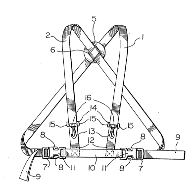
With reference to Fig. 1, the basic embodiment of
the invention includes a pair of identical shoulder straps 1
and 2, which are designed to fit over the shoulders 3 of a
user 4 (Figs. 4 and 5).
A connector defined by a disc 5 with a pair of
parallel, spaced apart slots 6 is used to interconnect the
straps 1 and 2 in overlapping relationship in the back area
of the user 4. One of the straps 1 and 2 overlaps one side
of the disc 5 and the other strap overlaps the other side of
the disc, the st~ap on one side of the disc extending through
the slots 6 and over-lapping the ~:trap on the other side of
the disc. Thus, the straps 1 and 2 are held firmly in
overlapping relationship, but can be slid longitudinall~ to
adjust the position of the disc S.
The male portion 7 of a conventional buckle of the
type including a pair of flexible fingers 8 is provided on
each free end 9 of each strap 1 and 2 for connacting the
latter to a chest strap 10. For such purpose, the female
portions 11 of the buckles are attached to the ends of the
chest strap 10. While the strap 10 has a fixed length, the
buckle portions 7 are slidable on the free ends 9 of the
straps 1 and 2 for changing the effective lengths of such
straps, i.e. permitting adjustment to suit the user's chest
-- 4 --
.
.
~ X~3x;~a~
dimensions. The other ends 12 of the shoulder straps 1 and 2
are sewn to the cross straps 10 near the ends thereof.
A swivel hook 13 is slidably mounted on the front
of each of the straps 1 and 2. The hook 13 includes a
generally U-shaped body 14 extending around the strap 1 or 2,
so that the hook can slide on the strap, and for pivotally
supporting the hook 13 for rotation around a horizontal
axis. Pins 15 extend through the arms of the body 14 into
the head 16 of the hook. The hook 13 is rotatablq in the head
16, so that the hook is rotatable around its own longitudinal
axis for facilitating attachment to an article to be carried.
A second embodiment of the invention ~Figs. 2 to 5)
includes the same basic elements as the carrier illustrated
in Fig. 1, and consequently wherever possible the same
reference numerals have been used in all figures. The
carrier of Figs.2 to 5 includes a trapezoidal plate 17,
which, as best seen in Fig. 3, has parallel top and bottom
edges 18 and 19, respectively, and downwardly and inwardly
inclined side edges 20. Horizontal slots 21 near the top
edge 18 of the plate 17 are designed to slidably receive the
straps 1 and 2, and vertical slots 22 near the bottom edge 19
receive the cross strap 10 (Fig. 2~. Slits 23 extend from
the bottom edge 19 of the plate 17 to the slots 22, so that
the plate can readily be attached and removed ~rom the strap
10. Similar slits (not shown) could be provided at the outer
~ 5 --
3Bl
ends of the slots 21, so that the plate could be removed from
the straps ~ and 2.
In use, the top end 24 of the plate 17 is tucked
into a bottom opening pocket 25 on the rear side of a small
article case or pouch 26, with the shoulder straps l and 2
extending through the slots 21, and the cross strap lO
extending through the slots 22. The pouch 26 has an
elasticized, top edge 27 ~Fig. 2), and is designed to snugly
hold a small article, in this case binoculars 28. The clips
13 are attached to the loops 29 (Fig. 5) conventionally
provided on binoculars. An overlapped portion 30 is provided
on the front or outer side of the pouch 26 for wrapping
around the top elasticated edge of the pocket 25 and the top
edge of plate 17 contained with the pocket 25, when the pouch
is to be closed to protect the contents o~ the pouch.
It will be noted that when the binoculars 28 are
removed from the pouch 26, they can readily be bP moved
upwaraly by sliding the hooks 13 along the straps 1 and 2.
The movement between the carrying position (Fig. 4) and the
use position ~Fig. 5) is smooth and silent, altering the
shape but not the dimensions of the carrier. Thus, the
binoculars (or other small article) are securely connected to
the carrier at all times, no disconnecting or re-c~nnecting
of the binoculars being required.