Note: Descriptions are shown in the official language in which they were submitted.
~Z~Z~'7~
APPARATUS AND METHOD FOR FORMING AND INSERTING
WAVE WINDINGS INTO A DYNAMOELECTRIC MACHI~IE STATOR CORE
This invention relates to a method and apparatus for
winding and inserting coils into a dynamoelectric machine
stator core. More particularly, the invention relates to
wave winding coils and inserting the coils into the slots of
a dynamoelectric machine stator core.
There has been an increased need for very small,
multiphase electric motors fGr use in automobiles and the
like to perform various functions.
However, prior art motor coil winding and insertion
methods have not been adapted to small motors. One prior
art method for manufacturing the stators for multiphase
alternating current dynamoelectric machines has been to wind
a coil for each phase and each pole and to insert the coils
into the slots of the core of a dynamoelectric machine, more
commonly called a stator core. Since each of the coils has
two leads, one problem with this method is the difficulty of
handling and connecting the many leads. Thus for a three
phase, four pole motor, twenty-four leads would have to be
handled and connected with this prior art method.
An improvement upon this prior art winding and
inserting method is to provide consequent windings for the
stator which would result in a total of six coils for a
three phase, four pole motor. This method thus results in a
total of twelve leads to be handled and connected.
A further improvement is to use the wave winding method
for manufacturing the coils since this method results in
three coils and a total of six leads. While the wave
winding method has advantages r one of the problems with this
method is that the prior art equipment for winding, forming
and inserting such coils is relatively bulky and because of
space re~uirements, needs to be located outside the
insertion tooling blade array. When a winding has been
wound on a coil form and then formed or shaped, the winding
must be stripped from the coil form onto the insertion
tooling. Prior art wave winding equipment and methods have
been limited to manufacturing relatively large motors. This
prior art equipment has not been successful in manufacturing
small motors since the wave winding forming elements could
not be moved inside the circular array of blades of the
inserting tooling.
In one prior art wave winding and inserting machine a
circular coil is first wound and a set of pulling members
restrains portions of the coil from radial inward movement
while a set of pushing members pushes alternating sections
of the coil radially inwardly, thus forming a star shaped
winding. The winding is then stripped from the winding and
former tooling and placed on the insertion tooling. By
necessity, due to the size of the pushing and pulling
elements, these members are located outside the insertion
tooling blade array. Due to the inherent resilience or
springiness of the coil wire, it is difficult to reliably
transfer coils so formed to the insertion tooling.
In another prior art machine, a curved set of forming
members is located above the insertion tooling blade array
and the forming elements have slots cut in their bottom
surfaces so that the top edges of the insertion blades can
be located therein during the transfer of the coils into the
inserting tooling. Thus, the front surfaces of the forming
member are disposed within an extension of the interior of
the circular array of blades. This method only partially
solves the transfer problem since the forming members are
not located inside the blade array. Furthermore, since the
forming members are still relatively bulky they cannot be
made small enough to transfer the windings for very small
motors such as, for instance, motors having a stator core
bore of one inch or less.
One prior art method for manufacturing these motors has
been to increase the size of the bore of the stator core and
the stator core slots, thus resulting in less stator core
material and poor slot fill and less efficient motors.
What is therefore desired is to provide a method and
apparatus whereby wave windings may be formed and inserted
in very small stator cores and wherein the forming members
extend into the interior of the insertion blade array for
positive transfer of the windings into the insertion
tooling.
The present invention, in one form thereof, overcomes
the disadvantages of the above described prior art methods
and equipment for winding, forming and inserting wave wound
coils into the stator cores of dynamoelectric machines.
The method comprises providing apertures in the coil
forming member whereby at least one of the insertion blades
may be inserted into each of the forming member apertures
whereby a portion of each coil forming member is located
inside the blade array and a portion of each coil forming
member is located outside the blade array during the
transfer of a coil from the coil form onto the insertion
tooling. Thus the coil forming members first form a coil
and after this the coil insertion blade array is moved
relative to the coil forming members and the coil form
whereby at least one of the insertion blades will extend
`` ~z~579
through the aperture of each forming mernber. Thus the coil
is stripped from the coil winding form and transferred to
the inserting tooling while the coil is retained in its
desired shape by the forming members.
An advantage of the apparatus according to the present
invention is that very small motors may be manufactured by
the method and apparatus since the forming members enter the
insertion tooling blade array. Furthermore the coils, as
they are being transferred from the coil form onto the
lU inserting tooling, will retain their shape.
The method and apparatus of the present invention
permits the insertion of coils in-to the slots of a stator
core with satisfactory slot fill and results in an efficient
motor. Furthermore the method permits the manufacture or
very small motor stators with wave windings whereby very few
leads need to be handled and connected.
The present invention, in one form thereof, provides a
method for winding, forming, and transferring a multipolar
sta~or coil in an apparatus including a coil form, a wire
former having an aperture therein, coil transfer tooling
having a plurality of insertion blades arranged in a
circumferential array and operatively associated with the
coil form and wire former. The method consists of
winding a coil on the coil form about a central axis and
then deforming the coil by moving the wire former radially
inwardly toward the central axis and a portion of the coil.
Relative movement is then effected between the coil transfer
tooling and the wire former whereby at least one of the
insertion blades enters the aperture in the wire former so
that a portion of the wire former is located within the
blade array and a portion of the wire former is located
12~Z579
outside the blade array. The coil is then stripped from the
coil form onto the transfer tooling.
The present invention, in one form thereof, provides an
apparatus for forming coils to be inserted into a
dynamoelectric machine stator core and for transferring the
coils to transfer tooling. The apparatus includes a coil
form including at least two spaced apart portions
symmetrically arranged about a central axis. A flyer is
provided for winding a coil on the coil form. Transfer
tooling is provided including a circumferential array of
insertion blades. A forming device deforms at least one
portion of the coil radially inwardly toward the central
axis. The forming device has an aperture for receiving at
least one of the blades of the transfer tooling therein.
Therefore, at least a portion of the forming device is
located within the space bounded by the array when the
transfer tooling is disposed in coil transfer relationship
with respect to the coil form and the forming means.
The present invention, in one form thereof, provides an
apparatus for forming and inserting coils into the slots of
a dynamoelectric machine stator core. The apparatus
includes a coil winding form having at least two spaced
apart portions symmetrically arranged about a central axis.
A winding member is provided for winding a coil on the
winding form. Transfer tooling is provided including a
circular array of insertion blades. The transfer tooling is
relatively movable with respect to the coil winding form. A
forming member is provided for forming radially inwardly
directed apexes in a wound coil, the forming member
including contoured radial inner surfaces. A stripper is
operatively associated with the coil form, the forming means
l~Z~7~
and the transfer tooling, to strip a coil from the coil form
onto the transfer tooling. The stripper is adapted to be
located within the circular blade array and includes
contoured surfaces adapted to cooperate with the contoured
surfaces of the forming means for deforming a coil
therebetween.
It is an object of the present invention to provide an
apparakus and method for winding and forming wave windings
and for inserting the windings into the stator core of an
electric motor.
It is a further object of the present invention to
provide a method and apparatus for manu~acturing stators for
very small motors.
Another object of the present invention is to provide a
method and apparatus for winding, forming and inserting
coils into the stator core of an electric motor whereby very
few leads need to be handled and connected.
Yet another object of the pres~nt invention is to
provide a wave winding and forming apparatus wherein the
forming elements enter the area bounded by the array of
insertion blades.
A still further object of the invention is to provide a
wave winding apparatus with apertured forming members so
that the insertion blades can be disposed in their coil
transfer positions relative to the winding form while the
forming members are retained in their operative forming
positions.
The above mentioned and other features and objects of
this invention and the manner of attaining them will become
more apparent and the invention itself will be better
understood by reference to the following description of an
7~
embodiment of the invention taken in conjunction with the
accompanying drawings wherein:
Fig. 1 is a plan view of a winding and transferring
station according to the invention for a coil winding,
forming and insertion apparatus;
Fig. 2 is a partial elevational view of a portion of
the winding and transferring station of Fig. l;
Fig. 3 is a plan view of a wire forming member for the
station of Fig. l;
Fig. 4 is a partial cross-sectional plan view of the
insertion tooling, wire stripping and wire forming assembly
for the station of Fig. l;
Fig. 5 is an elevational view of the insertion tooling
for the station of Fig. l;
Fig. 6 is a cross-sectional view of the center stripper
rod for the station of Fig. l;
Fig. 7 is an elevational view of the center stripping
rod of Fig. 6;
Fig. 8 is an end view of a side stripper rod for the
station of Fig. l;
Fig~ 9 is a cross-sectional view of the side stripper
rod taken along lines 9-9 of Fig. 8;
Fig. lOa, lOb, and lOc show the deformation of a coil
during insertion of the coil into ~he slots of a stator
core.
Corresponding reference characters indicate
corresponding parts throughout the several views of the
drawings.
The exemplifications set out herein illustrate a
preferred em~odiment of the invention, in one form thereof,
and such exemplifications are not to be construed as
79
limiting the scope of the disclosure or the scope of the
invention in any manner.
In Fig. 1 there is shown a plan view of the winding and
forming station 10. A coil form assembly 12 is shown
including left hand coil form portion 14a and right hand
coil form portion 14b. Furthermore, the coil form assembly
12 also includes coil form portions 15a and 15b for
purposes further explained herei,nafter. Coil form portions
14 and 15 are symmetrically spaced about a central axis.
A coil form mounting plate 16 is shown, as best seen in Fig.
2, for securing coil form portions 14 and 15 thereto
Coils 18 are wound on the coil form assembly 12 in a
conventional manner such as, for instance, by means of a
flyer whereby the elongated coil is wound about coil form
halves 14a and 14b. Alternatively the coil could be wound
about an arbor whereby coil form assembly 12 would rotate
about the central axis. The coil 18 is wound about a
section of reduced diameter of coil form halves 14a and 14b
whereby shoulders 20a and 20b prevent the coil from sliding
- 20 downwardly. Coil form halves 14a and 14b are inwardly
collapsible and are mounted upon guide shafts 22 whereby
coil 18 may be released. The coil form halves 14a and 14b
are secured to bearing blocks 26a and 26b which have
bearings 24a and 24b disposed therein. Coil form halves 14a
and 14b are urged inwardly by means of springs 30a and 30b.
Coil form half 14b is further adjustable relative to coil
form half 14a by means of slot 27 and threaded fasteners 28.
Thus by moving coil form half 14b relative to coil form half
14a, larger or smaller coils may be wound on coil form
assembly 12. Element 31 is gear shaft support ~or a gear
36. A cam 32, best shown in Fig. 1, cooperates with cam
~L2F~2~7~9
followers 34a and 34b for maintaining the relative spacing
of coil form halves 14a and 14b. Cam 32 has a contoured
surface 35 so that, as the cam is rotated by means of cam
gear 36 and a rack (not shown), the coil form halves 14a and
14b can be made to collapse under the inward urging force of
springs 30a and 30b. Cam 32 and gear 36 are secured to
shaft 33 with pins 37 and 38 and a retaining assembly 39.
As best shown in Fig. 2, a stripper assembly 40
includes a stripper mounting block 41 to which a center
stripper rod ~2 is secured by means of a threaded fastener
43. Four side stripper rods 44a and 44b are also secured to
block 41 by threaded fasteners 45. Stripper block 41 and
rods 43 and 44 are vertically movable by conventional means
tnot shown).
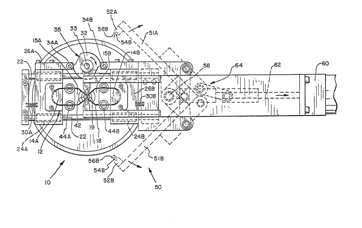
As shown in Figs. 1, 3 and 4, a wire former assembly 50
is shown including two former arms 51a and 51b on the
respective ends of which wire formers 52a and 52b are
mounted. The end portion of each wire former 52 includes an
aperture 54 as best shown in Fig. 3 for purposes explained
hereinafter. Each wire former 52 also includes a threaded
aperture 53 into which a threaded fastener is disposed for
securing wire formers 52 to arms 51. Each wire former 52
further includes a contoured surface 56 for purposes
explained hereinafter.
Former assembly 50 is operated by means of an air
driven cylinder 60 having a cylinder rod 62 for operating a
linkage 64. When rod 62 moves to the left as viewed in Fig.
1, wire formers 52 move radially inwardly toward the central
axis of coil 18. While a coil 18 is being wound by the
flyer (not shown) the coil formers are in the dotted line
position shown in Fig. 1. As best seen in solid lines in
~Z~
Fig. 1, after the coil has been wound, wire formers 52 have
been brought inwardly whereby the contoured surfaces 52 of
formers 56 are closely spaced to matching contoured surfaces
57 of center stripper rod 42, thereby capturing and forming
portions of the elongated sides of the coil between the
surfaces 56 and 57a so that the coil sides take an the
desired shape. Coil form sections 15a and 15b also have
contoured side surfaces to aid in forming the coil into the
desired shape with inwardly directed apexes as best shown in
Fig. 1. It should also be noted that while the forming
operation takes place, cam 32 simultaneously rotates thereby
causing coil form sections 14a and 14b to move inwardly
toward axis 19 and providing sufficient slack in coil 18 so
that the apexes can be formed.
The insertion tooling 70, shown in Fig. 5, comprises a
conventional circular array of insertion blades 72 and wedge
guides 74 disposed thereabout. Figs. 6 and 7 show the
construction of the center stripper rod of stripper assembly
40. A lower portion of the center stripper rod 42 includes
contoured surfaces 57 and surfaces 57a. Surfaces 57a form
shoulders 59 on the stripper rod 42 for stripping the coils
onto the insertion tooling. Stripper rod 42 also includes a
central bore 84 for receiving a coil separator pin located
on the center of a stripper (not shown) whereby a blade
alignment tool is pushed out of the blades ahead of the
uppermost turns of wire on the top coil. Furthermore
stripper rod 42 includes a central bore 86 for securing
stripper rod 42 to stripper mounting block 41 by means of
fastener 43. Figs. 8 and 9 show the side stripper rods 44A
and 44B which each include a slot 78 and tapered surfaces
lX~2~
80. Slots 78 capture coil 18 when it is stripped from coil
form 12 and transferred onto insertion tooling 72.
Referring to Fig. 4, it can be seen that each aperture
54 in wire formers 52 is shaped to accommodate a blade 72
and a wedge guide 74. Blades 72 and wedge guides 74 are
arranged in a circular array, as is conventional. The side
portions 90 of wire former 52 are dimensioned to fit in the
space which separates adjacent insertion blades 72. Thus,
it is possible for a portion 92 of each wire former 52 to be
disposed within the area inside the blade array and for the
remaining portion of the wire former 52 to be disposed
outside the blade array and wedge guide. As shown in Fig.
1, this arrangement is very advantageous as coil 18 may be
formed, after it is wound, and the insertion tooling 70 may
then be moved relative to the coil form assembly 12 and wire
forming assembly 50 while coil 18 is maintained in its
formed position. While the coil 18 is thus held and
restrained, the coil is stripped from the coil form assembly
12 onto the insertion tooling 70. Thus, it is assured that
the shape of coil 18 is positively maintained during
transfer of coil 18 into insertion tooling 70 by the coil
former assembly.
The operation of the equipment is as follows. Coil 18
is first wound about coil form 12 in a conventional manner.
During this time, coil form halves 14a and 14b are spaced
apart and are maintained in this position by means of cam
32. After coil 18 is wound and the coil wire is cut,
linkage 64 is operated by rod 62 whereby arms 51 and wire
formers 52 move radially inwardly toward the central axis 19
of coil 18. Simultaneously therewith, cam 32 rotates to
permit springs 30 to move coil forms 14 inwardly thereby
~ZF~2.~
providing sufficient slac~ in the coil so that wire formers
52 can move the sides of coil 18 inwardly. Surfaces 56 of
wire formers 52 then bottom out against the wire and
contoured surfaces 57 of the center stripper rod. Space for
coil 18 is provided between surfaces 56 and contoured
surfaces 57a. At this time, the sides of coil 18 will also
be disposed against the sides of coil form portions 15 as
best shown in Fig. 1. The transfer tooling 70 is now moved
upwardly whereby two of the blades 72 move respectively
into apertures 54 of respective wire formers 52. Stripper
assembly 40 is now moved downwardly whereby side portions of
coil 18 are captured in slots 78 of side stripper rods 44.
Coil 18 is also stripped downwardly by center rod 42 and the
abutment of coil 18 against shoulder 59. As the stripper
assembly moves further, coil 18 is stripped from coil form
assembly 12 and is inserted between respective blades 72 of
insertion tooling 70. Insertion tooling 70 together with
coil 18 is now moved downwardly relative to coil former
assembly 12 and former assembly 40. It should be noted that
either tooling 70 can be moved or coil form assembly 12 and
former assembly 40 may be moved to achieve the relative
movement of tooling 70 with respect to coil for assembly 12
and former assembly 50.
To form a three phase motorl three wave windings are
needed. Thus insertion tooling 70 is now rotationally
indexed through 60 while a further coil is wound onto coil
form assembly 12 and is then formed and transferred to
insertion tooling 70. The insertion tooling 70 is now
indexed through another 60~ while a further coil is wound
and formed. This coil is then transferred to tooling 70.
The insertion tooling is now moved to an insertion station
12~ZS79
(not shown) where a stator core is disposed adjacent and
above tooling 70 after which a stripper simultaneously
strips the three coils from insertion tooling 70 and
simultaneously places the three coils into the respective
slots of a stator core in a conventional manner.
If desired, three winding stations may be provided
whereby a first coil 18 is wound and transferred to the
insertion tooling 70 at the first station, a second coil 18
is wound and transferred to the insertion tooling 70 at a
second station, and a third coil 18 is wound and transferred
to the insertion tooling 70 at a third station. Thus, the
total operation may be speeded up by simultaneously
winding, forming and transferring coils at three stations.
Alternatively an indexed assembly could be provided with two
sets of coil forms whereby, as a coil 18 is wound on one set
of coil forms, another coil 18 is simultaneously formed and
transferred to insertion tooling at the second station.
By referring to Fig. lOa, it can be seen how the formed
coil 18 may be inserted into a stator core (not shown) to
magnetically form four poles. Apex portions 92 are formed
by wire formers 52 during the forming operations. When the
coil is transferred to insertion tooling 70 it has the shape
shown in Fig. lOa. After transfer of the coil to tooling
70, the coil assumes the shape shown in Fig. lOb since the
coil sides will droop down. Further still, when the coil is
stripped from insertion tooling 70 and is inserted into a
stator core, the coil will assume the shape shown in Fig.
lOc. Thus the coil sides 96 will be arranged in four
respective stator core slots, thereby in effect forming two
complete coils with the legs t:hereof being respectively 96a,
96b and 96c, 96d. Thus a single coil, as wound, formed ancd
1~257~
inserted, results in simulating two coils and forms four
magnetic poles.
While this invention has been described as having a
prefexred design, it will be understood that it is capable
of further modification. This application is therefore
intended to cover any variations, uses, or adaptations o~
the invention following the general principles thereof and
including such departures from the present disclosure as
come within known or customary practice in the art to which
this invention pertains and fall within the limits of the
appended claims.