Note: Descriptions are shown in the official language in which they were submitted.
3247-178
This invention relates to apparatus for eviscerating
scallops after they have been shucked.
After scallops have been harvested they have to be
shucked (removed from their shells) and then eviscerated, which
involves separating the membrane, entrails and roe (if any) from
the adductor muscle which is the meat por-tion most often consumed
by humans. Various arrangements have been devised for shucking
and/or eviscerating scallops but the present inven-tion is
concerned with the evisceration operation. The scallops to be
eviscerated can be shucked by known arrangements or by hand
although it is preferred that they not be subjected to heat
treatment which could cause partial cooking and accelerated
bacteria growth which may reduce shslf life and product appeal.
An apparatus for shucking scallops is disclosed in U.S. patent
4,361,933 of William K. Rodman, issued Dec. 7, 1982. Rodman uses
high volume, low pressure, water jets to strip frill and internals
from the meat. However, meat damage (splitting and erosion)
occurs at pressure and flow levels which could cause 80-90%
entrail removal, whereas a jet adjustment which does no damage
removes no frills and organs. Such damage is commercially
unaccep-table.
Another apparatus for processing scallops is disclosed
in U.S. patent 3,562,855 of Elmer Dryden Willis, issued E'eb. 16,
1971. rrhat apparatus, which uses a thermal and/or chemical bath
for shell removal, eviscerates the scallops by passing them over
an inclined bed of pinch rolls in a direction perpendicular -to the
roller axes. The counter rotating roller pairs oscillate, clock-
~Z8~ 3247-178
wise, and then counterclockwise, thereby stepping the product down
the incline. The rolls are covered with a rubberized abrasive
grit tape. Water sprays are used to regulate the residence time
of the scallops on the bed of rollers and to clean the rollers.
In practice, many of the scallops have to be recycled through the
eviscerator. This is due to gaps between roller centers due to
fixed bearing design and abrasive wear as well as clogging of the
"grit" by thin membrane waste. An eviscerator of the type shown
in this patent may have quite a large number of rolls, e.g. 80,
requiring numerous sprockets, a complex chain drive and several
horsepower to drive. The oscillator drive is also fairly
complicated and costly. The overall device is quite large in size
e.g. 42"x96" in comparison to its capacity and effectiveness.
Franken B.V. in Holland makes a roller bed mussel
debysser which is also capable of eviscerating scallops al-though
sometimes the liver and the roe sac do not pull through. Also,
thin tough membranes from the scallops wrap around the rolls,
reducing their roughness or "bite" which greatly reduces their
eviscera-ting ability. This device is essentially identical in use
and construction to the Willis clevice except that it uses
continuous roll rotation without oscillation.
The present invention provides apparatus for eviscer-
ating scallops which has only two continuously driven rolls and
thus is relatively small in size as compared to the prior art
roller-bed devices. The rolls are continuously cleaned to
; preserve their effectiveness. The apparatus as described herein
can process in excess of 100 scallops per minu-te with only ~
~'~8Z~
63247-178
horsepower required. This is adequate to post process the output
of 5 manual shuckers or 1 to 2 machine shuckers such as disclosed
in the above mentioned U.S. Patent 4;361,933. The apparatus is
effective at eviscerating a wide size range of scallops, does not
damage the scallop meat, and does not require any chemical bath,
heat treatment or "ageing`' of the scallops prior to processing.
Thus, in accordance with a broad aspect of the
invention, there is provlded apparatus ~or eviscerating scallops
after they have been shucked comprising an elongated generally
horizontally extending trough portion for receiving sald scallops,
said trough portion having a bottom slot, and comprising first and
second elongated rolls disposed in side-by-side relationship in
said bottom slot, said rolls defining a nlp in a vertical plane
between said rolls, said first roll having a knurled surface and
being provided with a left-hand-thread helical groove, said second
roll having a knurled surface and being provided with a right-
hand-thread helical groove, said apparatus having means for
; rotating said rolls in opposite directions so that their surfaces
enter said nip in a vertically downward direction whereby viscera
tend to be pulled from muscle portions of the scallops and through
said nip while said grooves move the scallops longitudlnally along
the rolls toward a dlscharge region, sald apparatus havlng rotary
cleaning brushes engaging sald rolls below sald Ylot and said
brushes engaglng flicker bars to clean the brushes.
The invention will now be further described in
conjunctlon with the accompanylng drawings, in which,
Figure 1 is a top view of apparatus for evlsceratiny
A
~Zg~7 3247-178
scallops according to the present invention,
Figure 2 is an elevational view, partly cut away and
partly in phantom, of the apparatus according to the invention,
Figure 3 is a cross-sectional view of the apparatus,
alony the line III - III of Figure 2,
E'igure 4 is an enlarged view of por-tions of the rolls
used in the apparatus according to the invention, and
Figure 5 is a simplified diagram of a portion of the
apparatus illustrating an alternative arrangement for moving
scallops along the rolls.
Figure 6 is a top view of apparatus according to the
invention similar to the embodiment of Figure 1 but using the
arrangement of E'igure 5 for moving scallops along the rolls.
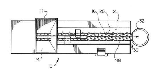
Referring to Figures l to 3, the apparatus for eviscer-
ating scallops is generally indicated at lO. The apparatus
comprises an elongated generally horizontally extending trough
portion 12 for receiving scallops (previously shucked) fed in via
a hopper 14 by an operator standing on side ~ thereof. A-t the
bottom of the trough portion 12 there is a slot 15 (Figure 3) in
which are mounted first and second elongated rolls 16 and 18 in
s'.de-by-side relationship and defining a nip 20 in a vertical
plane between the rolls. As best seen in Figure 4, the first roll
16 has a knurled surface and i8 provided with a left-hand-thread
helical groove 22. The second rol.l 18 also has a knurled surface
but it is provided with a right-hand-thread helical groove 23.
Means are provided for rotating the rolls 16 and 18 in opposite
directions, as indicated by the arrows in E'igures 3 and 4, so that
~Z~ 7 3247-178
their surfaces enter the nip 20 in a vertically downward direction
whereby viscera tend to be pulled from muscle portions of the
scallops and through the nip. The grooves 22 and 23 move the
scallops (not shown) long.itudinally of the rolls (to the right in
Figures 1 and 4, to the left in Figure 2) towards a discharge
region 30 from which they fall into a container 32. The viscera
pass through the nip 20, drop into the sloped bot-tom portion 17
and pass through a discharge chute 19 to a container 21 for
disposal.
Referring to Figure 3, rotatable cleaning brushes 36
and 37 engage the knurled surfaces of rolls 16 and 18 from below
the slot 20. The brushes keep the knurled surfaces of the rolls
from being clogged by the viscera and wrapping of thin membranes
which would impede their subsequent gripping action.
Flicker bars 40 and 41 mounted on a support 42 serve to
"flick" the bristles of rotating brushes 36 and 37 which are kept
clean by centrifugal force of rotation aided by the action of the
flicker bars. Cleaning of the rolls and passage of viscera
through the nip 20 is preferably aided by spraying water on the
rolls from nozzles, one of which is shown at 4~ in Figure 3.
To aid in ensuring that the viscera are caught in the
nip 20, and are nGt supported by the meat for the full resident
time, there may be provided a slowly rotating shaft 50 on which
are mounted a plurality of flexible "flipper" vanes such as 51
(see also Figure 2). These vanes turn the scallops as they move
along the rolls, sweeping them up the curved trough surface 12
until they slide down the vane and again onto the rolls in an
~829~7 32~7-178
inverted or random position. The trough sur-face 12 has bands of
rubberized abrasive grit tape fixed to it. Also found to be
effective is a single sharpened rigid vane running the full
processing length of the pinch rolls. Multiple water jets
directed across the pinch rolls with adequa-te pressure and volume
flow to roll or flip the product is a third effective (and
presently preferred) method, as illustrated in E'igures 5 and 6.
As seen in F'igures 5 and 6, piping 70 is mounted in any suitable
manner to extend from an inlet 71 to a straight section 72 extend-
ing along one side of trough 12 and then to an end section 73extending across the trough 12 near the end opposite the discharge
region 30. The piping 30 is provided with four fan jets 75-78 two
of which (75,76) discharge across the rolls 16, 18 and the other
two of which (77 and 78) discharge water along the rolls toward
the discharge region 30. All four jets provide horizontally
extending jets of water and assist in flipping the meats and
moving them along the rolls. Four jets are preferred but fewer or
more could be used.
The rolls 16 and 18, shaft 50 with flipper vanes 51 and
brushes 36 and 37 may be rotated by a motor 60 and any suitable
transmission such as a system of pulleys and flexible belts as
indicated generally at 61.
q'he rolls 16 and 18 are preferably 0.~75 inch to 1.00
inch diameter with a full depth 12 pitch 30 degree diamond lcnurl.
I'he pinch roller knurling pattern extends the full trough length
starting outside the feed hopper 1~ up to but no-t including the
ends supported near -the discharge region 30. Such rolls are
~ 2~ 7
3247-178
effective but do not damage -the scallop meats.
The rolls are preferably flooded with water to dissolve
and flush away the viscous slurry produced by crushing the
viscera. Meats leaving the rolls should be sprayed with clean
water to wash off crusted and other material. Dry rollers of the
correct size won't crush meats but viscous slurry can preven-t
entry of viscera into the nip.
The helical grooves in the rolls may be .050 inch deep
(root to crest) with a .050 inch radius. The firm meats engage
the helical grooves thereby positively transporting the scallops
axially along the horizontal pinch rolls while they are processed.
The grooves should not be too big or the meats may be pulled
through the nip. The thread pitch is preferably 2 to 4 per inch
and extends from within the feed hopper to the full extremity of
the roller discharge end. The pinch roller shafts are provided
with synchronizing spur gears at the drive end which maintains
face to face alignment of opposing knurl surfaces and helical
grooves. Correct alignment is shown in Figure 4. Referring to
Figure 4, the knurl pattern preferably has a plurality of parallel
longitudinal V-shaped grooves 80 cut into the knurl eor about the
firs-t 6 to 10 inches of the rollers. These V-shaped grooves may
be, eor example, 1/16 inch deep with sides subtending an angle of
about 30. The V-shaped grooves 80 damage the roe and liver
suEficiently to ensure they are caught in the nip between the
rollers and hence removed from the scallop meats.
By way of example and not limitation the rolls may be 32
inches long.