Note: Descriptions are shown in the official language in which they were submitted.
3~
Description
Lubricated S~line Joint
Technical Field
This invention relates to a spline joint for
connecting two rotatable members, and more
particularly to a spline joint that has a controlled
annular lubricating fluid mass associated therewith.
: Backqround Art
The fretting and progressive wear o~ spline
joint teeth has long baen a problem, and it has become
a recognized requirement to provide adequate
lubrication thereto. It has also been found that
merely allowing a lubricating fluid to pass over the
i splines is inadequate because at higher rotational
speeds and loads the lubricating fluid is thrown
outwardly so fast that the spline teeth surfaces still
experience such phenomenon.
In order to improve the service life of
spline joint-q lubricating fluid has been supplied
thereto in th~ form of an annular mass, with the
inside effective diameter of the spinning mass often
being limited by an annular dam adjacent one end of
the spline joint. Exemplifying the art in this area
are the following U~S. Patent Nos.: 3,242,695 issued
March 29, 1966 to P.Mv Ross, Jr; 3,~01,349 issued
January 31, 1967 to J.W. Williams; 3,380,555 issued
April 30, 1968 to J.D. Myers, et al; 3,589,471 issued
June 29, 1971 to R.G. Edge; 3,621,937 issued November
23, 1971 to R.G. Edge, et al and 4,281,~42 issued
August 4, 1981 to F.J. Gaeckle, et al.
A variation o~ the aforementioned prior art
is used commercially to connect an engine-driven
3;~00
~2--
flywheel member and the rotating housing input member
of a hydrodynamic torque converter. A seal ring forms
a dam at one end of the spline joint, and a radially
inwardly facing chamber that is accessible to
; 5 lubricating fluid is located at the other end thereof.
A plurality of relatively large diameter passages are
formed longitudinally in the radially inner housing
m~mber which are in open communication with the
chamber and the seal ring groove at the opposite ends
of the spline joint, and also with a radially
outwardly opening surface for the continual egress of
fluid from the region of the spline joint. In such
variation there is no attempt to accurately control
the rate of flow of fluid egress through the passages,
and the centrifugal pressure head is limited to
substantially the inside radius of the seal ring
and/or the radially outer portion of each passage.
One spline joint located between a flywheel
member and a torque converter housing member driven
thereby was observed to have substantial dynamic
activity. Particularly, the internal and external
teeth of the spline joint actually backed away from
the normal di~ection of engagement and then reenga~ed
in a pulsating manner during certain portions of the
operating speed range of the system. In order to
dynamically dampen this high speed cyclic activity,
the spline joint was submerged in an annular mass of
lubricating fluid to a radial depth sufficient to
provide a greater centrifugal pressure head than that
required for simply lubricating the spline joint. In
such instance an internal dam provided a fixed minimum
internal radius of the fluid mass around the spline,
and there was no attempt to circulate fluid through
the splines. However, experimental test results were
1~33;~)0
-3-
unsatisfactory at thP desired intermediate internal
radius value of the ~luid mass.
In high speed applications the centrifugal
action on the lubricating fluid mass can cause
separating forces parallel to the axis of rotation of
a significant magnitude upon the flywheel member and
the housing member, and these forces are imposed on
the bearings that support them. Consequently, it is
desired that the radial depth of the fluid mass and/or
; 10 the internal effective radius thereof be limited to
minimize such forces.
Accordingly, what is nePded is a lubricated
spline joint of relatively simple and economical
construction that can effectively and controllably
provide viscous damping of the cyclically induced
torsional vibrations of the system as well as reducing
wear of the splines. The spline joint should provide
the desired centrifugal pressure head while not
exceeding a preselected maximum pressure head range in
order to minimize thrust loads upon the bearings, and
should continually and controllably circulate fresh
lubricating Pluid through the splines to minimize
aeration and/or cavitation problems and to aid in
self-cleaning so that deleterious material does not
collect over a substantial period of time in
relatively dead-end pockets.
Disclosure of the Invention
The present invention is directed to
overcoming one or more of the above problems.
In one aspect of the present invention there
is provided a lubricated spline joint for connecting
first and second members rotatable about a central
axis and individually defining an internal spline and
an external spline respectively. Sealing means is
3~0(~
disposed near one end of the s;plines, a radially
inwardly fa~ing annular chamber is disposed near the
other end thereof, and a source of lubricating fluid
is accessible to the chamber. Advantageously, first
means is provided for establishing a preselected
minimum internal radius R of an annular fluid mass
submerging the splines to limit the centrifugal
pressure head thereof, and second means is provided
for controllably venting the Eluid mass at a location
radially outwardly of the radius R so that a portion
is continually dispelled as a result of centrifugal
~orce and fresh replacement fLuid is circulated
through the splines.
Preferably, the first means is defined
within the second member by an internal cylindrical
surface that essentially form~s a dam of the
preselected radius R, and by a cooperating plurality
of radially oriented passages that centrifugally
exhaust ~luid away from the cylindrical surface. The
second means is independent of the first means and
includes a plurality o~ passal~es formed in the
internal second member radi211y outwardly of the
;~ radius R so that fluid is controllably exhausted in a
generally longitudinal direction away from the chamber
and the splines. By controlling the rate of fluid
egress from the fluid mass relatively clean and/or
nonaerated fluid is caused to continually and more
evenly be distributsd over the submerged splines.
This markedly improves the viscous damping
characteristics of the joint, reduces wear, and
maintains the axial thrust forces as a result of thA
centrifugal pressure head at acceptable levels.
~ ~3;~
--5--
Brief Description of the Drawinas
Fi~. 1 is a fragmentary, longitudinal, cross
sectional view taken through the central axis of a
lubricated spline joint constructed in accordance with
the present invention and in the environment of an
engine-driven flywheel and a torque converter driven
thereby;
Fig. 2 is an enlarged fragmentary,
longitudinal, cross sectional view of the spline joint
illustrated in Fig. 1 showing details of the fluid
passages formed in the members thereof;
Fig. 3 is a transverse cross sectional view
taken along the line III-III of Fig. 2; and
Fig. 4 is an enlarged, fragmentary,
longitudinal cross sectional view of an alternate
embodiment housing member that can be used in place of
the housing member shown in Fig. 2 to form a
.: lubricated spline joint constructed in accordance with
the present invention.
,~ ~est Mode for Carr~ing Out the Invention
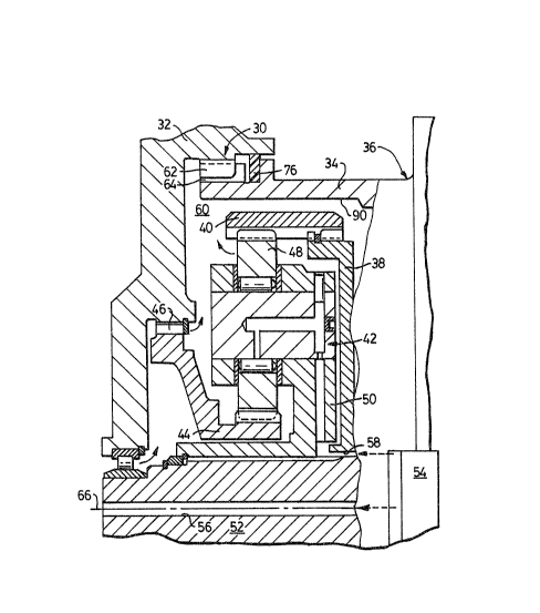
Referring to Fig. 1, a lubricated spline
joint 30 constructed in accordance with the present
invention is shown in the exemplary environment of an
engine-driven flywheel member 32 and a driven tubular
housing member 34 of a conventional hydrodynamic
torque converter 36, only a portion of which is
~ illustrated~ The torque converter is driven by the
.: housing member 34 and has an output element 38
drivingly connected to an internally toothed ring gear
40 of a planetary gear set 42. The planetary gear set
includes a sun gear 44 which is releasably connected
to the flywheel member 32 by a spline joint 46, and a
plurality o~ planet gears 48, one of which is shown,
are inter~eshingly engaged with the ring gear and the
1'~ 3330V
--6--
sun gear. $he planet gears are rotatably supported in
a planet carrier 50 which is connected to rotate with
an output shaft 52. The planetary gear set forms a
mechanical torque divider that is of interest
primarily only to indicate that a source 54 of
pressurized lubricating fluid is effective to
communicate the fluid to a central passage 56 defined
in the output shaft 52, and to a passage 58 defined
between the output shaft and the converter output
element 38. Thus, a fluid such as oil is directed to
the elements of the planetary gear set for the
lubrication thereof and is available in generous
amounts in a chamber 60 defined within the flywheel
member 32 and the housing member 34.
As shown best in Figs. 2 and 3, the first
flywheel member 32 of the spline joint 30 defines an
internal spline 62, and the second housing member 34
defines an external spline 64 which is intermeshingly
engaged with the internal spline. These splines are
generally concentrically arranged with respect to a
longitudinally oriented central axis 66. The flywheel
member 32 further defines an annular side wall 68
~; normal to the central axis adjacent one end of the
spline joint, and an internal cylindrical surface 70
adjacent the other end thereof.
An annular groove 72 is defined in the
housing member 34 between the external spline and a
back-up flange 74, and sealing means 75 is provided at
one end of the splines for preventing flow between the
members 32 and 34 which c2n experience relative motion
therebetween. The sealing means includes a seal ring
76 seated in the groove and which makes effective
sealing contact with the cylindrical surface 70 of the
flywheel member 32. Preferably, the seal ring is made
: 35 of a polymeric or elastomeric material which is
0~
-7-
adaptable to swell in the presence of a lubricating
fluid such as oil. For example, one seal ring
material that is preferred is of Viton synthetic
rubber material. Viton is a recognized tradename of
E.I. duPont de Nemours ~ Co. Inc.
The housing member 34 also defines an end
wall 78 which faces the side wall 68, and defines
therewith and with the flywheel member 32 a radially
inwardly facing annular chamber 80. This chamber i5
supplied with lubricating fluid by the centrifugal
action o~ the rotating members.
In accordance with the present invention,
the spline joint 30 includes first means or an
internal annular barrier as is indicated generally by
the reference number 84 for establishing a preselected
minimum internal radius R from the central axis 66 of
an annular fluid mass 86 entrapped around and
;~ submerging the splines 62 and 64. The annular barrier
; 84 thereby limits the maximum centrifugal pressure
head to a preselected range of values corresponding to
the speed of rotation of the spline joint. And
significantly, the spline joint further includes
second means or an exhaust device 88 for controllably
venting the fluid mass radially outwardly of the
radius R so that a portion thereof is continually
dispelled outwardly as a result of centrifugal force
and replacement lubricating fluid can circulate
through the spline joint 30.
More specifically, the internal annular
barrier 84 includes an internal cylindrical surface so
formed within the housing member 34 which essentially
defines the internal radius R from the central axis 66
as is shown in Fig. 2. A plurality of radially
oriented passages 92 are also defined fully through
the housing member which communicate with the surface
,
.
:. .. ,. , :
1;~83300
~8--
90 and an external peripheral surface 91 of the
housing member to limit the amount of lubricating
fluid collected on the internal surface 90 to a
substantially fixed value.
: 5 As shown in Figs. 2 and 3, the spline joint
exhaust device 88 includes a plurality of generally
longitudînally oriented venting passages 94 that are
defined in the housing member and individually spaced
within one tooth of the external spline 64. Each of
the venting passages has a first inlet 96 at one end
of the spline joint 30 communicating with the chamber
80, and a second inlet 98 in open communication with
the seal ring groove 72 between the opposite end of
the spline joint and the seal ring 76. Also, a
flow-restricting orifice lO0 is defined in each of the
venting passages which are in open communication with
~ the external peripheral surfact 91 in order to
: controllably limit the amount of fluid ~eing
discharged. These orifices are sized so that the
fluid discharge rate is less than the incoming supply
so that a full torus of fluid or annular fluid mass is
available.
~'
First Alternate Embodiment
Fig. 4 illustrates a first alternate
embodiment of the lubricated spline joint 30, wher~in
only the housing member 34' is illustrated as being
: modified from the housing member 34 of Fig. 2.
Particularly, the ori~ices 100' of the venting
: 30 pass~ges 94' have been drilled in a longitudinal
direction parallel to the central axis such that they
intersect and are in open communication with the
~: radial passages 92. From a manufacturiny standpoint
this is less costly than to drill the orifices 100 at
the inclined 45 angle shown in Fig. 2.
0~
- 9 -
Industrial A~plicability
In operation, the engine-driven flywheel
member 32 was rotated through an operating range of
from about 700 to 2000 rpm. Tests indicated that when
the venting passages 94 were not included, and when
only the internal annular barrier 84 and the radial
passages 92 were used that the fluid damping
characteristics of the spline joint were not
satisfactory. However, when the spline joint 30
illustrated in Figs. 2 and 3 was testedt it was found
that very desirable fluid damping was achieved. It
was theorized that the venting passages 94 are
extremely beneficial by continually purging
lubricating fluid and entrapped air from the region of
the spline joint. By continually having inlet access
to both ends of the spline joint any aerated ~luid
thereat is caused to continuously flow along the
venting passages and out the flow limiting orifices
100. The location of the venting passages at
substantially the radially inner portion of the spline
joint is beneficial in that proportionately more air
or cavitation is present thereat than at the radially
outer portion due to centrifugal forces. The flow
limiting orifices assure that the fluid mass ~6 will
build up in the chamber 80 to the radius R and have a
sufficient pressure head to provide significant
viscous damping characteristics~
In view of the foregoing, it is apparent
that the economical lubricated spline joint 30 of the
present invention not only includes first means 84
that assures an adequately sized annular fluid mass 86
to provide the desired centrifugal pressure head
range, but also includes second means 88 independent
of the first means for continually purging lubricating
fluid from the splines 62 and 64 at a location spaced
33~
,
--10--
radially outwardly of the inner radius of the fluid
mass so that relatively fresh and less aerated fluid
is available to effect the desired degree of viscous
damping of the splines. ~hus, lubricating fluid
5 having the desired characteristics is available at a
particularly effective range of pressures to more
uniformly coat the individual spline teeth, and yet
the thrust loads produced by the rotating fluid mass
are also maintained within practical limits.
Other aspects, objects and advantagPs of
this invention can be obtained from a study of the
drawings, the disclosure and the appended claims.