Note: Descriptions are shown in the official language in which they were submitted.
~283~
KNIFE 8LADE AND METHOD FOR MAKING SAME
BAC~GROUND OF THE INV~NTION
The invention relates generally to knife blades
and deals more particularly with the construction of and
the method for making knife blades for cutting sheet
material which blades exhibit some self sharpening
characteristics.
A blade of the general type with which this
invention is concerned is shown in U.S. Patent 3,681,846
to Gerber. The '846 blade has three layers, a relatively
hard layer sandwiched between two relatively soft layers.
In one embodiment of the '846 blade, the inner Layer is
made of tungsten carbide and the two outer layers are
made of steel or aluminum. An outer face of each outer
layer is bevelled, and ideally, the two bevelled faces
converge upon an exposed edge of the inner, relatively
hard layer such that the exposed edge of the inner layer
protrudes slightly from the outer layers forminq a
cutting edge or peak to the knife blade. The outer
, ~
~.Z !33q~
--2--
layers support the inner layer. In this embo~iment, the
thickness of the relatively hard inner layer varies in
the longitudinal direction of the cutting edge so that
the cuc~ing edge wears unevenly forming a serration.
EventuaLly, the cutting edge dulls and may be sharpened
by one or two grinding wheels which bear against both of
the outer, relatively soft layers of the blade.
It has proven difficult to accurately grind the
two outer faces of the relatively soft layers such that
the peak of the blade is formed exclusively by the
exposed edge of the inner layer. The reason is that it
is difficult to align the grinding wheel such that its
axis is precisely parallel to the plane defined by the
inner layer and misaLignments of only a few thousandths
of an inch result in the peak of the blade being
partially formed by the outer, relativeLy soft layers, in
which cases, the blade dulls easily.
Accordingly, a general object of the invention
is to provide a knife blade for cutting sheet material
which bLade does not dull easily.
A more specific object of the invention is to
provide a blade of the foregoing type which does not
require precise sharpening.
~ Another specific object of the invention is to
provide a knife blade of the foregoing type which
exhibits some self-sharpening properties.
Another general ob~ect of the invention is to
provide methods for making the cutting blades of the
3- ~,83~
foregoing type.
Other ohjects of the present invention will
become apparent from the fol~owing detailed description.
SUMMARY OF THE INVENTION
_ _
The invention resides in a knife blade used for
cutting sheet material. The blade may be installed in an
automatic cutting apparatus which reciprocates the blade
d~ring cutting. ~he knife blade comprises a cutting
portion having a base and a coating on a portion of the
base, the base being formed ~rom a reLatively hi~h wear
material and the coa~ing being formed from a relatively
low wear material.
According to one feature of the inventio~n, the
relatively low wear material may be harder than the high
wear material~ The cutting portion has two ad~oining
faces; one of the faces is formed by the relatively low
wear, hard coating material and the other face is formed
by the relatively high wear soft base material. With "
this design, the relatively low wear, hard coating on the
cutting portion is always exposed to the workpiece to
provide effective cutting. Also, the relatively high
wear, soft face tends to wear more rapidly than the
relaeively low wear, hard face exposing the relatively
low wear, hard face further and providing a degree of
self-sharpening.
According to another feature o~ the invention,
either face of the cutting portion may be provided with
, ,
.
~ _4_ ~36~
an alternatirlg sequence of hills and valleys, the valleys
intersecting a cutting edge to provi~e serrations which
facilitate the cutting.
B~IEF DESCRIPTION OF THE FIGURES
Fig. 1 is a ~ragmentary side view of a cutting
apparatus including a knife blade which embodies the
invention.
Fig. 2 is a sectional view of the blade of Fig.
1 taken along the line 2-2.
Figs. 3-5 illustrate steps in a method for
producing the blade of Fig. 1.
Fig. 6 is an ~nlarqe~, fragmentary side vie~J of
a modified for~ of the knife blade of Fi~
Fig. 7 is a fragmentary plan view of another
cutting blade which embo~ies the invention.
Fig. 8 is a sectional view of the knife blade of
Fig. 7 taken along the line 8-8.
Figs. 9-11 illustrate a metho~ for producing the
knife bLade of Fig. 7.
Fig. 12 is a fragmentary side view of another
knife blade which embodies the invention.
Fig. 13 is a sectional view of the blade of Fig.
L2 taken along the line 13-13.
DETAILED DESCRIPTION OF THE PREFERRED EMBODIMENTS
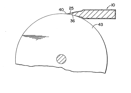
Turning now to the ~rawings, Fig. 1 illustrates
a knife bla~e generally designate~ 10 which embo~ies the
i~
-5- ~2~3
present invention. The bla-le 10 is received in a cuttinq
head 12 of an automatic cutting apparatus 13. The
apparatus 13 includes a penetrable worksheet supporeinq
bed 15, a means for reciprocating the blade lO in a
direction perpendicular to the bed l5 and a means for
moving the blade in an X-Y plane paralLel to the bed 15.
Sheets 17,17 of fabric are supported on the hed 15 for
cutting. The cutting head 12 includes a hlade holder 14,
a nousing 19 having a guide slot through which the blade
10 and blade holder 14 reciprocate, and a movable
grinding assembly 18 for sharpening the blade 10. For a
further description of a cutting apparatus which may be
used to reciprocate a knife bla~e and move it in an X-Y
plane parallel to a support surface, reference may be
made to U.S. Patent 3,805,650 to Pearl issued April 23,
"r,'~j
1974.
As shown more cLearly in Fig. 2, the blade 10
comprises a cutting portion 24 and a strentheninq portion
26 integrally connected to one another. ~y way of
example, the blade is 3/16 inches front to back (left tO
right in Fig. 2), and is .028 inches thick at its
thickest portion.
In the illustrated embodiment, the cutting
portion 24 incLudes two bevelled cutting faces 2S and 36
which converge upon one another to yield a cutting edqe
40. Both of the faces 25 and 36 may have a slight
cylindrical concav1ty due to hollow grindin~ of the base
836~
- --6--
material. The hollow ground increases the sharpness of
the cutting portion 24. Both of the faces 25 and 36 form
approximately the same angle relative to a plane 37. The
plane 37 bisects the blac3e 10 and so, defines a natural
cutting direction or plane for the blade 10 so that the
cutting portion has a generally symmetrical cross-section
and provides a minimal resistance to cutting.
The blade 10 is formed from an inner base or
support body 30 of relatively high wear material and an
outer relatively wear resistant coating 32. In the
illustrated embodiment, the outer coating 3~ surrounds
alL of the base 30 in its final form except for the face
36 of the cutting portion 24. To provide a coating which
is more wear resistant than the base 30, the coating 32
is formed of a harder material than the base 30. By way
of example, the base 30 is made of hardened tool steel
having a hardness of 60 Rockwell C or softer and the
outer coating 32 is made of titanium nitride having a
hardness of i30-90 Rockwell C. The thickness of the outer
coating may be in the range 0.1/1,000 inches to 1/1,000
inches with a s~ggested thickness of 0.5/1,000 inches
which thickness is substantially uniform throughout the
coating. When the blade 10 is sharp, the cutting edge 40
i defined primarily by the exposed edge of the coating
32. A thin coat is desirable to yield a sharp cutting
edge but the coat should not be so thin as to rapidly
break during cutting. The titanium nitride also provides
the blade in general with ~ low coefficient of friction
~` ~2a360~
--7--
to make it easier for the blade to slice through the
sheet material.
~ ecause the material of the outer coating 32 is
more wear resistant than the material of the base 30, as
the blade 10 reciprocates and cuts sheet material or
other workpieces, the noncoated face 36 of the cutting
po{tion 24 wears more rapidly than the coated face 25 of
the cutting portion 24. Consequently, during usage, the
cutting edge 40 of the cutting portion 24 may remain
defined, to a large extent, by the exposed edge of the
coacinq 32 on the face 25. This is desirable because the
relatively hard edge of the coating 32 is generally
better than the softer base material for cutting. ~lso,
the coating 32 is made thinner and therefore sharper than
the base of the cutting portion 24.
While the material of the base 30 of the cutting
portion 24 wears in a very gradual manner by the removal
of fine particles of the base material, the exposed edge
of the coating 32 on the cutting portion may tend more to
wear by chipping due to brittle fracture as the base
material recedes and the adjacent coating loses its
support. The brittle fracture property of the coating 32
may be advatltageous for cutting certain types of sheet
material because it makes the cutting edge 40 jagged or
serrated which in many instances provides more effective
cutting than a smooth cutting eclge of the same sharpness.
AppLicant believes that the cutting portion of the blade
10 will remain sharp enough to cut 1,000 to 10,000 linear
" _f3_ ~2a31~0~
inches of ~abric on the fold, enough to cut one to ten
men's suits.
If the coating 32 on the cutting portion 24
recedes more rapidly than the adjacent base material, the
face 36 may be ground by the grinding wheel assembly 18
to again expose the coating 32 at the cutting edge. The
grinding assembly 18 comprises an arm 39 which is
pivotally mounted to the housing 19 and a grinding wheel
43 which is carried by the arm 39. The arm 39 may be
; pivoted downwardly so that the grinding wheel engages the
face 36 with an axis 41 of the wheel parallel to the
cutting edge 40.
The strengthening portion 26 gives the bl~de
lateral stiffness so that as the blade 10 moves in a
nonlinear path in the X-Y plane and the worksheets 17,17
and penetrable bed 15 exert lateral forces on the cutting
portion 24, the cutcing portion 24 is able to resist
deflection. Also, the strengthening portion provides a
grip for the blade holder 14.
Figures 3-5 illustrate a method for producing
the blade 10. ~nitialLy, as shown in Figure 3, the base
30 is provided of hardened steel, which base may be
formed by a machininq process. Then as shown in Fig. 4,
the base 30 is coated with the titanium nitride. In the
illustrated embodiment, the coat covers virtually the
entire surface of the base 30 includinq both faces 36 and
25 of the cutting portion 24.
;
_9_ ~Z~3~0~
The coating 32 may be ~ormed by one of various
commercially available processes, such as a "Titan ~ote"
(TM) chemical depositing process provided by Richter
Precision Incorporated, or a chemical depositing process
provided by Blazers Tool Coating, Inc. of ~orth
Tonawanda, New York. In their chemical depositinq
processes, suitable compounds are mixed to form titanium
nitride gases which are then chemically bonded to or
deposited on the surface of the base 30. An ion bonding
process may also be used to form the coating 32.
Next, as shown in Fig. 5, the face 36 of the
cutting portion 24 is ground by the grinding wheel 43 or
another grinding wheel to remove the associated portion
of the coat 32, to sharpen the cutting portion 24, and to
expose an edge of the coat 32 tO form the cutting edge
40. Herein lies a virtue of the design of the blade 10.
Because the face 25 is coated with the relatively hard
material and is exposed to the sheet material during
cutting, even if the grinding wheel is somewhat
misaligned so that its axis is not aligned precisely
parallel to the plane 37 and the cutting edge is not
defined entirely by the exposed edge of the coating 32
but is partially defined by the base material 30, the
blade 10 will still be effective in cutting because one
side of the cutting portion will still be defined by the
very hard coating material. Moreover, as the cutting
portion wears, the relatively soft base material located
at the cutting edge will tend to wear faster than the
I o ~2~33
adjacent, relativeLy hard coating causinq the cutting
edge 40 to be defined more and more by the coating
material and less and less by the relatively soft base
material.
I'he grinding wheel 43 may have a surface covered
by either fine or coarse grit. ~f the fine grit is
utiLized, then the blade ]0 may be reciprocated during
the grinding process to ensure uniform grinding and to
provide the face 36 with a smooth surface. If the coarse
grit is utilized, it may score the face 36 and the
exposed cutting edge 40 to make the cutting portion 24
ragged or serrated. If the coarse grit is utilized on
the grinding wheel 43, then the blade 10 may not be
reciprocated in some cases or may be reciprocated slowly
in other cases while the ~rinding wheel engages ~he
cutting portion 36 so that the scores produced by the
grit intersect the cutting edge 40.
Fig. 6 illustrates the blade 10 after it has
been scored by the coarse grit and worn to a small degree
by usage.
Scores 45,45 in the base material of the face 36
cause the cutting portion to have an uneven thickness
along its length so that the cutting portion wears
unevenly on both faces, and so, yields a more jagged or
serrated cutting edge from usage than would normally
occur through brittle fracture of the coating 32. The
scores 45,45 are perpendicular to the cutting edge
because the blade 10 is maintained stationary during the
-- ~LZ83~
grinding process.
It is also possibLe to form the cutting portion
24 by starting with the machined base 30 of Fig. 3,
masking the face 36, coating the unmasked sur~ace of the
base with the titanium nitride an~ then removing the
mask. This avoids the subsequent grinding step.
Figures 7, 8, and 12 illustrate another knife
bLade generally designated 110 which embodies the present
invention and which may be installed in the cutting head
12. The blade 110 is formed ~rom an inner body or base
130 and an outer coating 132, which base and coating may
be ~ade of the same materials as the base 30 and coating
32 of the blade 10, for example, hardened steel and
titanium nitride, respectively. The coating 132 may also
be applied by one of the chemical ~epositing processes
described above. The thickness of the coating 132 is
also similar to that of the coating 32, 0.1/1,000 inch to
1/1,000 inch with a suggested thickness of .05/1,000 inch
as a trade-off between sharpness and St rength. The blade
110 comprises a cutting portion 124 and an integrally
connected, strengthening portion 126.
The cutting portion 124 has tWO hollow ground
faces 140 and 1~2, which ~aces intersect or converge upon
one-another to ~orm a cutting edge 14~ and are angled or
bevelled relative to a plane 147 which bisects the blade
110 and defines a natural cutting plane or direction for
the blade 110. The face 140 is coated with the
relatively hard material and has ridges or corrugations
, ~ ~Z~33~0~
for~ed byan alternating sequence of l~ills 143,143 and
valleys ~5~145 The cutting edge 146 is primarily
defined ~ the coat 132 on the face 140 and is jagqed or
Serratedtue to the hills 143,143 and valleys 145,145.
The strengehening portion 126 helps the cutting
portion l24 to resist lateral deflection, provides a grip
for the ~ade holder 14, and is identical in design to
the strengthening portion 26 of the blade 10.
rigures 9-11 illustrate a method for making the
blade 11~ Initially, the body or base 130 shown in Fig.
9 is proiided, for example, by an appropriate machining
process. Grooves 148,14~ are cut in a face 139 of the
base 130 which grooves are perpendicular to a cutting
edge 146 of the blade 110. By way of example, the
9rooves 148,14~ are 1/1,000 inch to 5/1,000 inch ~eep.
The grooveS 148,148 are shown to be evenly spaced
although this is no~ necessary.
Next, as shown by the front view of Fig. 10, the
base 130 is coated, and in the illustrated embodiment,
the coating covers virtually the entire surface of the
base 130. The coating has a substantially uniform
thickness and therefore takes the shape of the cutting
portion 124 including the corrugated shape of the face
140 forming the hills 143, 143 and the valleys 145,145-
~ ext, as shown in Fig. 11, the face 142 of thecutting portion 124 is ground by a grinding wheel 150
having an axis 152 parallel to the cutting edge 146. The
grinding wheel 150 removes the hard coat on the face 142,
` -13- ~3~
and cucs back the exposed portions of the valleys 148,
148 along the cutting edge 146. This adds jaggedness to
the cutting edge 146 as shown in Fig. 9, the expose~
edges of the hills 143, 143 forming protruc1ing teeth of
the cutting edge 146 and the exposed edges of the valleys
145, 145 forming recesses between the teeth 143, 143. The
recesses are somewhat deepened by the grinding process.
The cutting edge 146 has a saw tooth form which is
effective in cutting. Moreover the cutting ability is
not directly dependant on the sharpness of the cutting
portion 124 so that the cutting portion 124 is able to
cut effectively even after the cutting edge 146 wears and
dulls somewhat. ~ote also that because the face 142 is
formed by the relatively soft and high wear material, the
face 142 wears more rapidly than the coating on the face
140 and therefore recedes from the cutting edge 146 ancl
the coat or the face 140 to aid in maintaining the
sharpness of the cutting portion 124.
After a significant amount of cutting, the
cutting portion 124 may become dull, and a grinding
process may be utilized to sharpen it. The grinding
wheel 150 or the grinding wheel 43 may be used t~ sharpen
the cutting portion 124. Because the face 140 is coated
and exposed to the sheet material during cutting, even if
the grinding wheel is somewhat misaligned so that its
axis is not precisely parallel to the plane 147 and the
cutting edge is not defined entirely by the exposed edge
of the coating 132 on the cutting portion 124, the blade
3L~83~1
. .
110 will sti~l be effective in cuttinq becallse one side
of the cutting portion will Still be defined by the very
hard, coating material.
Figures 12 and 13 illustrate another knife blade
generally designated 210 which embodies the present
invention. The knife blade 210 may be received wiehin
the cutting apparatus 13 and comprises a cutting portion
224 and a strengthening portion 226 integrally connected
to one-another. The cutting portion 224 includes two
bevel~ed cutting faces 225 and 236. Both of the faces
235 and 236 may have a slight cylindrical concavity due
to hollow grinding of the base material of the cutting
portion 224. Both of the faces 22~ and 236 form
approximateLy the same angle relative to a plane 237.
The plane 237 bisects the blade 210 and defines a natural
cutting plane for the blade 210 so that the cutting
portion has a generally symetrical cross-section and
provides a minimal resistance to cutting.
The blade 2lO is formed from an inner base or
inner support body 230 and an outer, wear resistant
coating 232. In the illustrated embodiment, the outer
i coating 232 surrounds all of the base 230 in its final
form except for the face 236 of the cutting portion 224.
The coating 232 is formed of a harder more wear resistant
material than the base 230. By way of example, the base
230 is made of hardened tool steel having a hardness of
60 Rockwell C or softer and the outer coating 232 is made
of titanium nitride having a hardness of 80-90 Rockwell
2836(~
-15-
C. The thickness of the outer coating may be in the
range .1/1,000 inches to 1/1,000 inches with a suggested
thickness of 0.5/1,000 inches which thickness is
substantially uniform throughout the coating. When the
blade 210 is sharp, a cutting edge 240 is defined
primarily by the expose~ edge of the coating 232. A thin
coat is desirable to yield a sharp cutting edge but the
coat should not be so thin as to rapidly break during
cutting. Except for the cross-sectional shape of the
blade 210, the blade 210 is very similar to the blade 10,
both in design and performance, and is produced in a
similar manner. The blade 210, like the blade 10, may be
provided with grooves which intersect the cutting edge
240.
By the foregoing, knife blades embodying the
present invention have been disclosed. However, numerous
modi~ications and substitutions ~ay be made without
deviating from the scope of the invention. For example,
if desired, the width of the strengthening portions 26
and 126 of the knife blades 1~ and 110 respectively may
be decreased and bevelled to aid the blades in slicing
through the sheet material. Also, if ~esired, either
face of the cut~ing portion 24 or 124 may be made
parallel to the cutting planes 37 and 147, respectively
and the other face made bevelled to intersect the other
face of the cutting portion.
Also, if desired, either or both faces of the
cutting portions 24,124 or 224 may be made flat without
i -~6- ~Z~3~
the cylindrical concavity of the aforesaid hollo~ ~round.
Therefore, the invention has been disclosed by way of
iLlustration and not by limitation.