Note: Descriptions are shown in the official language in which they were submitted.
7'3~
KEY LOCK WITH KEY ISO:LATION
BACKGROUND OF rrllE - INVENTION: -
This invention relates to locks which have settable
elements like disks, levers, or other forms of "tumblers" that
can be set by a key.
Nearly all locks can be described, in a-general sense,
in the following way. They consist of an external memory which
can be a key or a card or simply the intelligence of the
-operator. The lock is proviaed with an internal memory. There
must be a provision by which the two memories can be made to
interact. Ihis can either be a slot in the lock through which a
key can enter, or a slot for a card, or a dial or knobs to be
operated manually by the user. In some recent technology, this
interaction can even be a device that reads the fingerprint, the
size of the users hand, or any other arrangement of sensors that
can connect the outside world to the inside memory of the lock.
The lock has a fourth major device that can detect the
coincidence between the outside and inside memories. If the
coincidence is correct, this fourth element permits the lock to
open. This may be an electronic device that provides the proper
signal, and it may be a mechanical device that permits a bolt to
be withdrawn.
It is obvious that locks can be defeated in one of two
principal ways. The first is by brute force; that is, the lock
can be broken, cut out, drilled, or otherwise damaged and
neutralized. Some such techniques can be quite subtle in that a
small hole can be drilled through which the internal mechanism
can be examined and manipulated.
The second method for defeating a lock, and the problem
~j~
7~3;~ -
ad~ressed in this invention, is the general means called
"picking" or surreptitious entry. In this approach, th-e lock is
not damaged in any way, but by the use of proper instruments
coupled with skill of the operator, the internal mechanism can be
manipulated ana the lock opened.
In order to defeat this type o~ surreptitious entry, a
great many expedients have been invented. Torque senSing
devices, complicated keys, complicate~ tumblers and disks, time
delay mechanisms, an~ a great many other techniques have been
designed and produced. I myself have three patents on such
expedients. They are U.S. Pat. Nos. 3,172,2~3; 4,111,01g; and
4,4~5,64~-
U.S. Pat. Nos. 2,52~,964; 1,702,430 and 180,225 appearto be related to my subject invention. They discuss the
~rincipal idea of blocking the key slot before the lock can be
opened. They do not, however, close the key slot completely or
isolate the key from the tumblers. In one case, the key is made
to have a wide flange and a rather narrow neck so that most of
the key slot can be cLosed, but the passage to the tumblers from
the outside worl~ remains open although, as the patent clearly
states, the passaye is somewhat tortuous. In the others, the key
slot is only partially closed.
U.S. Pat. No. 2,179,947 to ~. Miller is much closer to
the subject of my invention. ~ere a sn,all key is inserted into
the lock ano is completely "swallowed" before it can be opened.
The key slot is closed and the lock is turned by a handle. When
the action of the lock is finished, the key is ejected from the
lock. The disadvantage of having to use a key that cannot be
conveniently carried as a ring or in a key, that has a very small
7''~
head, and that can get stuck in the lock because of dirt,
congealed oil or a slight bend in the key, are~ too obvious to
need further discussion.
SUMM~RY OF THE INVENTION:
My invention assumes that in a conventional key-
operated lock, where the key sets a series of elements (such as
aisks, levers or other types of what are sometimes called
tumblers), it is possible to reach the elements through the key
slot and manipulate them while testing their position by torquing
the cylinder or pushing back on the bolt or doing something
equivalent. Admitte~ly, some locks are difficult to pick in this
way because of the aforementioned efforts in àesigning the
various components. Nevertheless, as long as there is access
between the outside world and the control elements of the lock
there is always the possiblity of such manipulation. In the
present invention, I have designed a system where the key sets
-the elements, as in conventional locks, but then the key and the
key slot are moved away from the elements and are captured in
what may be called an isolation con~partment. The external world
is then completely physically blocked from any connection between
the key slot and the elements that control the opening of the
lock. It is only after this-has been accomplished and the
physical openiny to the lock-is completely isolated from the
internal memory that the fourth element of the lock, the fence or
its equivalent, can test the position of the elements to see if
they were correctly set.
7~.~
B~IEF DESC~IPTION OF TIIE DkAWINGS:
Figure 1 shows the front face of my lock in one
embodiment. The key slot is open.
F'igure 2 shows the same face after a key has been turned
counterclockwise approximately 1~0 . The key is not shown in
Figures 1 and 2 for clarity.
Figure 3 shows a section taken approximately on the line
3 - 3 of Fiyure 1. This figure shows a simplified form of the
two co-acting cylinders, one for holding a key and the second
acting to isolate it from the rest of the lock under certain
conditions.
E`igure 4 shows a key cut to set three levers.
Figure 5 is taken approximately on line 5 - 5 of Figure
3, and shows the main components of the lock under the front face
of the lock. The position of components is shown with the key
slot in the initial position.
E~igure 5A shows a detail of the construction of a
(detent) push-pin used in sotne of the embodiments.
Figure 6 shows the lock mechanism as in Figure 5 except
that the key is in the cylinder.
Figure 7 shows the position of the components when the
key has just set the levers.
E~igure 8 shows the components with the key trapped and
isolated from the levers.
Figure 9 shows the lock set to be unlocked but not yet
turned, with no key in lock (for clarity).
Figure 10 shows the main lock cylinder partly turned.
Figure 11 shows the lock opened (main cylinder turned).
Fiyure 12 shows the condition of the lock when the
7~
levers were not set correctly.
Figure 13 shows a- different embodiment of my lock which
is similar to that of Figure 5 except that instead of levers, I
now have three disks set by the key.
- Figure 14 shows a key to cooperate with a lock in Figure
13.
Figure 15 is the same as Figure 13 except that the key
is in the cylinder.
Figure 16 shows the key trapped and isolated from the
10 disks, after the disks have been properly set by the key.
Figure 17 is the same as Figure 16 with the key not in
its cylinder.
Figure 18 shbws the lock after it has been unlocked.
(The main cylinder has been turned).
Figure 19 shows a different embodiment of my lock, front
view. The dotted line shows the position of the key as it sets
the levers.
E`igure 20 shows the key designed for this lock.
Figure 21 shows a cross-section taken roughly parallel
20 to the main axis of the lock cylinder.
Figure 22 shows the main features of the inside of the
lock taken as a section roughly along line 22 of Figure 21.
Figure 23 shows the mechanism after the levers had been
set correctly and the inner cylinder has been rotated counter-
25 -clockwise. The lock is now unlocked.
Figure 24 shows the relative positions of the key slots
in the outer case of the lock and in the top surface of inner
cylinder.
Figure 25 shows a different embodiment of my lock. It
7~3.'~
is similar to that~shown in Figures 1 to 12. The lock is shown
in section as it is i-n the locked condition.
Figure 26 is a sectionview showing the lock after it has
been unlocked by a proper key.
In all oE the embodiments, the interlock between the key
space and the fence is such that the fence must be moved away
from contact with the elements before the key slot can be turned
back to its initial, open position. This motion also resets all
the elements into their starting positions. They then have no
relation to their positions for opening the lock.
DETAILED DESCRIPTION OF THE DRAWINGS:
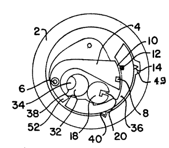
Figure 5 shows a schematic diagram of the principal
working elements of my invention. The lock consists of an outer
case 2 which may be a cylinder containing the working parts. A
multiplicity of levers 4 are pivoted at 6. Each lever has a
notch 8 in the appropriate position for the lock to operate.
Faciny the working edges 10 of the levers 4 is a fence 12
operated by a push pin 14 the end of which is in a notch 49 in
the ~uter casing 2.
A small cylinder 18 is provided with a keyway slot 20
and a key 22 can be inserted into this slot 20 when the cylinder
18 is in the correct initial position as shown in Figures 1 and
5. This is determined by the plate 24 which is fixed to the
outside case 2. Thus, the key 22 can enter the lock or be
removed from it in only one position.
When the key 22 is turned counterclockwise, the various
raised bits 26 of the~key 22 move the levers~4 as shown in Figure
7. The-levers 4 are held in position by friction resulting from
the force provided by spring washer 28. The sectors are
7~'~
separated by fixed plates 30 so that the motion of one sector 4
is not communicated to another.
After the key 22 has set the sectors 4, it continues its
counterclockwise rotation until it reaches its final position as
shown in Figure 8.
Geared to the cylinder 18 containing the key slot 20 is
another cylinder 32 (Fig. 3) which has a sector 34 cut outl as
shown in the figures 5 to 12. it is designed so that the working
portions of the key 22 can enter this cut-o~t section 34 as the
cylinders 18 and 32 rotate with each other. In the final
position shown in Figure 8, the two cylinders 18 and 32 have
rotated so as to trap the key 22 and/or its slot so as to isolate
them from the rest of the mechanisms in the main cylinder 36
(Fig.~).
E'ormed on the outside surface of trapping cylinder 32 is
a cam section 38 (Fig. S) which serves two functions. In the
position of Figure 8 it contacts cylinder 18, thus acting to
provide a better seal between space containing the key 22 and the
wor-king elements o~ the lock. Its second function is to reset
the levers 4 as will be explained below.
After the two cylinders 18 and 32 have finished their
rotation (Fig. 8) and have now trapped the key 22, a pin 40 is
- in position to enter the hole 42 in cylinder 18 (See Figs. 8 and
5A). With the key 22 in this position, this pin 40 acting
25 against the cam surface 44 as notch 45 enters hole 42 (See E'ig.
5A) and permits the main cylinder 36 to turn.
- Further motion of the main cylinder 36 causes the fence
pin 14 to be pushed in by the cam surface 48 of the notch 49 in
the outside body 2 (See Fig. 10) and to move the fence 12 into
7~3.~
the notches 8 of the levers 4, if they had been previously
correctly set. '[his permits the major cylinder 36 to continue to
turn. If, however, the notches 4 had not been properly aligned,
the fence 12 cannot enter the notches 8 of the levers 4 and the
ma~or cylinder 36 cannot be turned. It should be noted that in
this position (k`ig. 8 to 12) there is no way by which any tool
can reach the levers 4 to manipulate them except, of course, by
drilling the lock or by other damaging means. ~ote that notch 49
is much wider than notch 45.
When it is desirea to reset the lock into its initial
position, the key 22 is turned clockwise. Cylinder 36 is turned
clockwise and the cam 38 operating against the ends 52 of the
sectors 4 (E'ig. 5) resets them all into the position shown in
Figures 5 ana 6. The key 22 finally reaches the clockwise
position shown in E'igure 6 and can be removed from the lock. All
this can only occur if the two pins 40 and 14 are as shown in
Figures 5 and h.
The number of levers 4 can be as large as desired,
dependiny on the size of the lock and the precision of
construction tha~ can be economically achieved. For exarmple,
eight or ten levers present no special problem and each lever can
have five to ten possible positions. It is obvious that with
normal tolerances of key construction and other mechanical
uncertainties, the number of possible positions of each element
has to be kept to some reasonable value. Five or six notch
pOSitiQnS are very easy to accomplish in an ordinary lock. If
the lock is made larger, the number of possible positions can be
greatly increased.
In rny lock, it should be noted, that because the key 22
~37~<3~
is removed from contact with the elements 4, the elements are
held in posi-tion by friction as is done unlversally in
combination locks. While I show levers 4 which are not balanced
against the forces of gravity or shock, they can be easily
arrange~ to be so. Each lever can be counterbalanced if the lock
does not have to be crowded into the smallest possible space.
Counterbalancing is particularly easy to do with the embodiment
in Figure 13. Here the only cut-outs that have to be
counterbalanced are the two notches 100 and 102 and this can be
easily done by putting a hole in the disk on the opposite side.
I foun~ that using a spring washer 104 or 28 (in the yrior
embodiment) to provide the necessary friction is much simpler and
is entirely satis~actory.
If a master key is desired, some of the sectors 4 can
have more than one notch 8 and this is well understood in the
prior art. It should also be noted that if the fence 12 is
narrow, the number of yossible positions can be larger. This is
also true if the fence 12 has very sharp corners and the notches
8 have e~ually sharp corners. Then, even a small amount of
misalignment between the notches and the fence prevents the Eence
feom entering. This action is also well understood in the art.
It is also possible to design a lock using the same
basic principle explained so far but where the key instead of
lifting levers, rotates disks (See Figs. l~ to 18). This design
resembles the internal construction of a typical combination
lock. There are two obvious methods of doing this. One is to
gear each lever 4 of the lock of my first embodiment (Figs. 5 to
12) to a disk so that moving the lever rotates the disk. This
may be an advantage in-that a relatively small motion to the
1~37~t;~
lever can produce a large motion of the disk so as to spread the
fence entering notches over a large circumference. The same
thing can be done, of course, by making the levers very large,
but the overall size of the lock is often an important
consideration.
A metho~ of making a key turn disks directly is shown in
Figures 15 and 16. Here the key 106 has raised ~ortions, or
bits, 108 of various heights and the key 106 can enter suitable
notches 102 in the disks 110, and as the key 106 (Fig. 15) turns,
10 each disk 110 is moved through an appropriate angle. A high bit
108 rnoves the disk through a large angle, and a lower bit 108
moves a disk 110 through a smaller angle, and where there is no
raised key section 112, the disk 110 stands still. The key shown
in Figure 14 is therefore of three bit heights, 0, 1, and 2, as
15 shown.
Each disk 110 is provided with a notch 100 into which a
fence 114 can enter. With the exception of resetting the disks
llOwhich, in this case, is done by the key itself, the operation
of the lock is similar to that of E`igures 5 to 12.
In the embodiment of r~`igures 13 to 18, I show a
different arrangement of pin interlocks to assure that the key
lOb can be turnea. ~he pin 118 is bifurcated into two arms 120
and 122. Arm 120 is designed to enter hole 124 as the key 106
starts to turn cylin~er 126 counterclockwise to open the lock.
25 Arm 122 is terminated in fence 114.
The lengths of the two arms 120 and 122 are so
proportioned that arm 120 is closer to the cylinder 126 than
fence 114, at the end of arm 122, is to the disks 110. This is
done so that the arm 120 must enter hole 124 before the fence 114
37~'~
can determine whether the disks 110 were set correctly. Thus the
key 106 must turn the cylinder 126 to the position shown in
Figure 16 before the fence 114 can cause the lock to open. in
this position ( Eligure 16) the key is isolated from the lock
opening mechanism as was done in the prior-described embodiment.
Here, again, two cylinders 126 and 128 are geared together.
Cylinder 12~ has a sector 130 cut out so as to form part of the
isolation chamber for the key 106.
As in the previous embodiment, separator plates 132 are
located between the disks 110 so that turning one disk does not
move another.
If the disks 110 were set correctly by the key 106, the
fence 114 enters the notches 100 and the inner cylinder 116 can
rotate, being no longer prevented from doing so by the pointed
15 pin 118.
When the lock cylinder 116 is rotated back to its
initial position, pin 118 moves back into notch 134 (Figure 16).
This retracts arms 120 and 122 and the fence 114, The key
cylinder 126 is now ~re~ to r~tat~ and the key can rest disks 110
into their initial positions as shown in E`igures 13 and 15.
Figure 17 shows the positions of the lock components if
a pick is used to turn the cylinders 126 and 128 into the
positions shown. The arm 120 can enter the hole 124 in cylinder
126, but the fence 114 cannot enter the notches in the
incorrectly set disks. In this configuration, there is no
physical path available to the pick to reach the disks from
outside the lock.
Figure 18 shows the lock after it has been unlocked by a
proper key.
,
3'7~
It should be noted that in the case of a lock where--
elements are set by a key which then, in effect, is removed from
further cooperation with the lock, the lock can be considered to
be a combination lock. The action of a fence entering levers or
disks in my lock is not different from that which occurs in a
conventional combination lock. It is-no easier to test the
posltion of the levers or disks of my lock than it would be to
test the position of disks in a conventional combination lock.
As a matter o~ fact, because a key can set a much greater number
of elements than a dial, such a key lock offers greater
protection against surreptitious tampering than the conventional
combination lock. A naive question arises as to why not use many
more disks in a conventional combination lock. The difficulty
with such approach is that when a conventional lock has more than
three disks, the setting becomes very difficult. With ten disks,
one would have to spin all of the disks first in one direction
an~ then set the first number, then rotate the setting dial in
the other direction nine times, set another number, then rotate
the dial eight times, etc., etc. This is very difficult to do
without mistakes and as far as I know this is never done. With a
key setting the disks, however, there is no problem of having ten
disks or levers, or any other number.
In a combination lock, it is sometimes possible to
detect the differences in height among the three disks. The
problem becomes very difficult if one tries to do that with ten
levers or other such elements. Because these levers can be
stamped out by a single die, there is no problem of making them
identical. This is much easier than turning the disks-to the same
exact diameter as by a lathe. This last consideration I do not
37~
consider very important technically, but it is a factor in
considering the cost of locks.
Another embodiment is shown in Figures 19 to 24. Its
settable elements 200, which can be conventional levers, are set
by a key 202 as before, but instead of the key 202 being isolated
from the levers 200 by a trapping mechanism, the isolation is
accomplished by removing the key 202 from the lock entirely and
then closing the key slot 204 completely before any attempt can
be maae to test whether the levers 200 (or other elements) have
been set correctly.
To accomplish this, I show in Figures 19 to 24 a lock
having an outside rigid case 206, an inner rotatable cylinder 208
whose top 210 is fitted closely to the upper plate 212 of the
case 206. I show a space between them in Fig. 21 for clarity
only. The inner cylinder 208 has a shaft 214 protruding through
the top 212 of the lock. A knob 216 mounted on the shaft 214
provides the means by which the inner cylinder 208 can be
rotated. Figure 22 is taken roughly along the plane 22 - 22 of
Figure 21. In the initial condition (Fiy.22) the key slot 204 in
20 the top 212 of case 206 is aligned with a similar key slot 218 in
the inner cylinders top plate 210. Thus, when the two slots
are aligned, the key 202 such as shown in Figure 20, can be
inserted into the lock. It is-then turned counterclockwise
(viewed from above) approximately 45 to set the levers 200.
The key 202 after setting the levers 200 is shown by
dotted lines in Figure 19. The inner cylinder 208, of course,
cannot be turnea by the knob 216 because the key itself prevents
this. For the lock to be opened, the key 202 has to be removed
entirely. The lock cylinder 208 cannot be turned clockwise
7~
because of the shape of the spring pin~220, (See Fig. 22). The
knob 216, however, can be turned counterclockwise. This
automatically closes the key slot 218 because the two slots 204
and 218 are no longer aligned. The new position of the slot 218
in the inner cylinder is as shown in Figure 24. If the levers
200 had been set correctly, a fence 222 operated by the pin 220
acted upon by cam surface 224, enters the notches 226 in the
levers 200, as in Figure 23. The inner cylinder 208 can now
continue turning counterclockwise. it can then operate the rest
of a conventional lock mechanism that need not be shown here.
When it is desired to close the lock, the knob 216 is
turned clockwise but passes down the cam surface 224, fence 222
is withdrawn from the lever notches 226 and the levers 200 can
now be reset. This is done by a vertical rod 228 seen in Figures
21, 22 and 23. It is mounted on plate 230 pivoted at pin 232
mounted on and concentric with the inner cylinder 208. A ball
detent 234 operated by a spring 236 mounted in the outer,
stationary body cylinder of the lock 206 pressés against the
plate 230 so that as the innee cylinder 208 is rotated clockwise
the plate 230 is held back by ~riction because of the detent 234.
The rod 228 acts to reset all the levers 200 back to their
initial position before the two key slots 204 and 218 are
aligned. The lock now is ready for another operation.
In order to increase the friction between the detent 234
25 and the plate 230 the plate can have a serrated edge and the ball
detent can be replaced by a pointed pin to increase the forces
between them. The embodiment shown is by way of an example only
and ratchets of various types are well known to the art so that
the plate 230 can be held back as the inner cylinder is rotated
14
37~1~
clockwise (looking from above).
Figures 25 and 2h show still another embodiment of my
invention. The design is similar to the first embodiment, as
shown in Figures 1 to 12, and the drawings are simplified
schematics taken just below the front plate of the lock as was
done in Figure 5.
The lock has an outside body cylinder 300 and an inner
cylinder 302. To open the lock the inner cylinder 302 must be
rotated. This is identical in operation with a great many locks
used throughout the world.
~ ounted inside cylinder 302 are a set of levers 304 that
must be correctly set by a key 306 so that a fence 308 should be
able to enter notches 310 in these sectors 304.
A key cylinder 312 is located in the inner cylinder 302,
and is provided with a key slot 314. The key 306 that can be
identical to key 22 as shown in Figure 4, can be inserted through
a suitable key opening 20 in the top plate 24 of the lock as
shown in E`igures 1 and 3.
Unlike the lock of L;`igures 3 to 12, this last embodiment
does not contain a second cylinder (32 of Figures 3 and 5) to
isolate the key 30~ after it has set the sectors 304. Instead,
I use a swinging plate 316 pivoted on shaft 318. The plate 316
is driven by a small diameter pinion gear 320 affixed to shaft
31~ his gear 320 is acted upon by a short rack 322 that is a
part of pin 324.
The resetting of the levers 304 is accomplished in a
manner somewhat si~ilar to that of the first embodiment (Figs. 3
to 12), except that the key cylinder 312 itself has a cam 326 at
its lower end for this purpose. The cam 326 acts on a sliding
7!~.~
pin 328 mounted for lengthwise movement in the base of the
cylinder 302. A vertical rod 330 is fastened to the pin 328 at
its left end as seen in Figures 25 and 26 and this vertical rod
330 resets the levers 304 when the key cylinder is rotated
clockwise to its initial position as seen in Figure 25.
The key cylinder 312 is provided with a small hole 332
into which pin 334 must enter before the lock can be opened.
- The action of the fence-pin 336 and of the fence 308 are
exactly as described for the pin 14 and fence 12 in the first
embodiment.
For this lock to be opened, a propér key 306 is inserted
~ into key slot 314 in the key cylinder 312. The key 306 is turned
counterclockwise about 300 degrees till it is stopped by the
solid parts of the inner cylinder 302 as shown in Figure 26.
The pin 334 acted on by the cam surface 338 of the notch
340 (in the outer case 300) moves into the hole 332 of the key
cylinder 312, and the rack 322, acted on by the cam surface 342
of the notch 344 swings the plate 316 into the position shown in
dotted lines in Figure 26.
The inner cylinder 302 is now free to continue rotation.
The fence pin 336 reaches the cam surface 346 of the wide notch
348 in the outer case 300, and because the sectors 304 had been
correctly set, as stated, the fence 308 enters the notches 310
and the lock can be opened.
It can be noted that in this embodiment for the lock to
open the path from the key slot 314 to the sectors 304 is very
long and torturous so that even if the isolation plate 316 were
somehow to fail in its function, picking the lock would be
extremely difficult.
i6
7~3~
When. the cylinder 312 is returned to its original
position, as shown in Figure 26, the pin 334 is withdrawn from
the hole 332 by its spring 350 and the key 306 can now be turned
clockwise to the position shown in Figure 25 so that it can be
withdrawn from the lock. As the key 306 is turned clockwise, the
cam 326 acts on the sliding pin 328, and the rod 330 acting on
the ends 352 of the sectors 304 resets them to their normal,
unlocked positions, as shown in Figure 25.
Another consideration in the design of my invention is
that the levers are held in position by friction and do not need
springs as used in almost all conventional lever locks. This is
an important consideration in designing locks for low price and
high reliabi-lity.