Note: Descriptions are shown in the official language in which they were submitted.
9~
Description
Positiv0 Keeper Means For Pins Of Earthworking Tips
Technical Field
This invention relates generally to a pin
retainer assembly for securing an earthworking tip to
~n adapter on an earthworking device and more
particularly to a keeper means for positiv~ly securing
the pin in the apertures in the tip and the bore in
the nose of the adapter.
Back~round Art
Replaceable earthworking tips or teeth
commonly used on rippers, loader buckets and trenchers
must be positively secured in place on their support
adapters and yet be capable of quick removal for
; replacement purposes. In addition to the monetary
~value of the tip that is lost, the loss of the tip
will subject the adapter to damage requiring time
consuming expensive repairs and/or replacement.
Loss of the tip, when used in conjunction with rock
crushing equipment, causes severe damage to the
equipment should it become digested or jammed therein.
Prior art retaining pins for securing an -
earthworkins tip on its adapter have not been totally ~ -
successful especially when used in combination with
impact rippers. In such appIication, the retaining
plns are subjected to extreme vibration resulting in
breakage of the pins or the retaining mechanism
becoming loose causing loss of the pin and the tip.
TypicalIy, retaining de~ices have been
empIoyed which relies ~n friction between mating
~ sur~aces for retention. U.S. Patent 3,624,827 issued
;~ 35 ~ ~ ~
~ :
-:
,: . . . .:. ~ :
. .
., . . : : : -
33~39
to Richard R. Liess et al on November 30, 1971
discloses a retaining pin having a friction ring
disposed in a deep, wide, central groove of the pin.
The pin is retained in a hore defined by the adapter
nose solely by friction between the ring and the bore.
Although this type o~ pin has been successful in
normal ripper and bucket tip retaining applications,
the central groove materially reduces the strength of
the pin and subjects it to early ~ailure in extremely
severe applications. In addition, the pin can vibrate
out of the bore since it is not positively retained.
U.S. Patent 3,959,901 issued to Gene R.
Klett on June~l, 1976 discloses another friction type
retaining device in which the pin is retained solely
by frictional engagement of the retaining pin with a
lock ring~ As before, vibration allows the pin to
work its way loose resulting in loss of the pin and
the separation of the tip from the adapter.
U.S. Patent No. 3,952j433 issued to
Lloyd K. Heinold, et al on~April 27, 1976 and U.S.
Patent No. 3,990,162 issued to Lloyd K. Heinold, et al
on November 9, 1976 disclose spring clips that
straddle diametrially opposite sides of the retaining
pin in expanded friction engagement. The clips are
~ substantially encapsu1ated by an elastomeric material
which aids in maintaining the spring clips in
frictional engagement with the pins. Undesirably, the
spring clips~only partially engage the pins and the
pins are easily removed by the spreading of the spring
30~ clips.
Accordingly, an improved earthworking device ~ -
is provided so constructed that the earthworking tip
is retained on the nose of ~he adapter by a pin that
is positively retained in aligned apertures in the
earthworking~tip and the bore o~ the adapter.
,-, . . .
. . : , :: , . .
:' -'. , : ' . -
~8~939
~3--
Preferably, the retaining pin is positively secured
by a keeper means that is simple and economical in
con~truction while maintainîng the pin against outward
axial movement during operation of the earthworking
device.
The present invention is directed to over- -
coming one or more of the problems as set forth above.
Disclosure of the Inventio~
In one aspect of the present invention, a
retaining pin and a keeper means adapted for use in an
earthworking device having a nose and a tip
telescopically mounted on the nose, the nose has a
transvers~ bore and laterally converging sidewalls,
and the tip defines a mating socket with laterally
spaced apart converging sidewalls defininy a pair of
aligned holes th~rein axially aligned with the
transverse bore, and a recess defined in one of the
nose and the tip in axial alignment with the
20 transverse bore and the holes, the retaining pin ~ -
ha~ing an ou~er peripheral surface with an annular
groove defined in the outer peri~heral surface;
: characterized in that, the keeper means includes a
metallic washer and a resilient retaining ring, the
washer has a frusto-conical side surface and an inside
sur~ace defining a bore with an annular groove opening
in the bore, the keeper means when assembled is
disposed in the recess, and the pin is disposed in the
aligned bore and extendæ substantially through the
holes of the sidewalls to retain the tip on the nose,
the pin begin slidably disposed within the bore of the
: metallic washer, and the~ring has a cross-section with
~ a predetermined radial thickness and is disposed in
:~ locking engagement within the groove on the pin and
the groove in the washer, the depth and configuration
~,. .
- . -
,.' ~: ' ' ' ' ' ' ' ' '. ' ', . : - '' ' ' ,.
~: ' - - ~ . - -
: ~
,:
~L~83939
~,, _
of the groovas being sufficisnt to prevent camming of
the ring out of the grooves, the ring, in use, is
oparative in conjunction with the grooves in the pin
and the washer to prohi~it disassembly of the pin from
the washer without an external force being applied to
the pin suPficient to shear the ring or to fracture
the washerO and one of the sideæ of the wacher being
operative to cooperate with one of the lateral
sidewalls of the nose or the tip to e~fectively
concentrate the external force close to the interface
of the grooves.
In another aspect of the present invention,
an earthworking device including an adapter having a
nose with forwardly converging lateral sidewalls and
defining a transverse bore, an earthworking tip
telescopically mounted on the nose of the adapter and
having a pair o~ spaced apart forwardly converging
lateral sidewalls and a pair of laterally aligned
holes de~ined in the sidewalls, the bore and the holes
being substantially axially aligned, a recess formed
in one of the ~ose and th earthworking tip and in
substantial axial alignment with the bore and the
: : holes, a cylindrical pin having a groove and during
: assembly being slidably disposed in ths bore and th
holes for retaining the tip on the adapt~r;
characterized by, a keeper means for securing the pin
in the bore being located in the rec~ss ~or abutting
contact with the nose and one of the sidewalls, the
kaPper means including a metallic washer and a split
: 30 resilient retaining ringj the matallic washer having a
; frusto-conical side sur~ace disposed adjacent one of
the pair o~ spaced apart forwardly converging lateral
sidewalls of the earthworking tip or one of the
; ~ ~orwardly converging lataral sidewalls of the nose and
~ 35 an inside ~urface defining a bore and a groove opening
e~ :~
:,
., ~ .
~, , . . ., : , ,, : ' .,
', ,-, ~ . , '- , ~ '
, - , . . .
~L~8~39
-4a-
into the bore, the bore of the metallic washer being
axially alignabls with the bore in the nose, the
resilient retaining ring having a cross-section of a
predetermined radial thickness captured in one of the
grooves in the pin and the washer and adapted during
assembly to permit ~lidabl~ insertion of thP pin in
the bore and the holes ~or locki~g engagement o~ the
retaining ring with the other of the grooves, the
depth and configuration of th2 groove~ being
sufficient to prevent camming of the ring out of the
grooves~ and the retaining ring and washer being a
configuration suf~icient to prohibit disassembly of
the pin without an sxternal force being applied to the
pin sufficient to shear the retaining ri~g or to
fracture the ~asher with eaçh of the sides of the
washer constructed to effectively concentrate the
force close to the interface of the grooves.
Brief Descrlption of the_prawinas
Fig. 1 is an exploded isometric view of an
: aarthworking device comprising an earthworking tip
retained on the nose of an adapter by a retaining pin
and a keeper means of the present invention;
Fig. 2 is an enlarged cross-sectional view
of an assembled earthworking device;
Fig. 3 is an enlarged partial sectional view
taken in the direction of:arrows III-III in Fig. 2;
Fig. 4 is an enlarged cross-sectional viPw
of the resilient retaining ring located in the groove
of the pin and the groove of the washer;
~:~ : Fig. 5 is an enlarged cross-sectional view
of an alternate embodiment of the resilient retaining
ring; and
: :
~ : : 35
- . .
. . ~ . . . . .
.
3~3~
Fig. 6 is an enlarged cross-sectional view
of an alternate embodiment of the subject invention.
Best Mode f _ Carrying Out the Invention
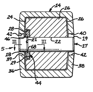
Referring to Figs. 1, 2, 3, and 4 an
earthworking device ~0 comprising a support member or
adapter 12 having a tip 14 detachably mounted by a pin
retainer assembly 7 5 on a forward end or nose 16
thereof. The pin retainer assembly 15 includes a
7 0 rylindrical pin 17 which has an outer peripheral -
surface 20 and an annular groov~ 21 defined therein.
A pair of beveled surfaces 18 and 19 are provided at
the intersection of the outer peripheral surface 20
with the ends of the pin 17. The nose 16, preferably
of wedge shape, defines a transverse bore 22 and a
pair of ~orwardly converging lateral sidewalls 24 and
26. It is noted that in some adap ers 12, the
sidewalls 24 and 26 may not be forwardly converging
but be substantially parallel. A recess 28 having an
~ 20 end wall 29 is formed in the lateral sidewall 24 of
: th~e nose 16 and in concentric relationship with the
bore 22.
A wedge-shaped socket 30 is formed in the
~ :: tip 14 to accommodate the like-shaped nose 16 of the
: 25 : adapter 12. The nose preferably terminates at its
apex defined by a surface 32 adapted to at least
partially abut a surface 34 formed at the apex of
recess 30 in the tip 14.
Tha tip 14 ha~s a pair of forwardly
converging spaced sidwalls~36 and 38 and a pair of
laterally aligned holes 39 and 40 defined by
: peripheral surfaces 41 and~42. The sidewalls 36 and
: 38 are normally designed to cQnform generally tG the
sidewalls 24: and 26 of the nose 16. The holes 39 and
: 40~straddle bore 22 in the nose 16 and are in
,
.
.. ~ - , :
- .
- . :
- ~2~33~3~
substantially axlally alignment therewith.
As best shown in Figs. 2 and 3, the pin
retainer assembly 15 also includes a keeper means 44
mounted in the recess 28 formed in the lateral wall 24
of the nose lS for securing the pin 17 in the bore 22 : -
of nose 16. It is recognized that the recess 28 could
equally be formed in lateral sidewall 26 of the nose
16 or in either of the sidewalls 36 or 38 of the tip
without departing from the subject invention.
The keeper means 44 includes a washer 46
10 having an inside surface 47 defining a bore 4~ with a . .
radial annular groove 50 define~ in the washer and
opening into the bore. The washer 46 is preferably
made of metallic material or any oth~r suitable
material. The washer 46 further has a flat inner side
: 15 surface 52 adjacent the end wall 29 of the counterbore
: 28 and a fru~to-conical outer side ~urface 54 adjacent
the sidewall 36 of the tip 14. It should be
recognized that a similar outer frusto-conical surface :--
could be on the opposite side of the washer 46 without
departing from the essence o~ the subject invention.
; As best shown in;Fig. 4, the groove 50 of
~ : : the washer 46 has a pair of generally parallal
: ~ ~ sidewalls 56 and 58 and a bottom surf ce 60 spaced
from the bore 48 defining a predetermined depth A for
the groove.
The groove 21 in the pin 17 has a pair of
enerally parallel sidewalls 62:and 64:and a bottom
surface 66 spaced from the outer peripheral:surface 20
of the pin 17;defining a predetermined depth B for the
~groove. :~
The:keeper means 44 also includes a metallic
: split resilîent:retaining ring 68. The retaining ring
68 has a cros -section:that is generally rectangular
with a pair o~ generally parallel sidewalls 70 and 72
;35 ~ defining a predetermined width~C and a pair of
::: :: : ::: : :
::
: . . - . -: - . ~ : - . .
. . - ::
.
.. . .
~L28393~3
generally parallel inner and outer surfaces 74 and 76
defining a predetermined radial thickness D. The ring
68 is slidably capture~ in the groove 50 of the washer
46. The ring 68 may be composed of a conventional
spring steel or like material which exhibits the
desired resiliency, hardness and spring back
capabilities required for pin retention purposes.
The pin 17 in the assembled position is
slidably disposed within the bore 22 of the nose 16,
the bore 48 of the washer 46 and extends substantially
through the holes 39 and 40 of the sidewalls 36 and 38
of the tip 14. The ring 68 is disposed in locking
engagement with the groove 21 of the pin 17 and the
groove 50 in the washer 46.
Pref~rably, the depth A of groove 50 in the
.. ..
: ~ washer 46~'has depth A'is equal to or greater than the
predetermined radial thickness D of the ring 68~ The
predeterminPd~depth B of the groove 21 in the pin 17
is generally equal to one half of the predetermined
radial thickness ~ of the ring 68.
~:: : Referring now to Fig. 5, an alternate
:embodiment of the presenk invent~on is illustrated and
: includes a split resilient retaining ring 78 having a
cross-section that is generally circular with a ;~
predetermined radial thiGkness E.
`: The ring 78 is slidably captured in the
groove 50 o~ the washer 460~ A bottom surface 80 of
: the ~roove 50, spaced from t~e bore 48, has a profile
generally corresponding to:the ciruclar cross-section
of the ring 78 and defines a depth F for the groove.
.
The groove 21 in the:pin 17 has a root
pro~ile 82 generally corresponding to the circular
cro~s-section of the ring 78:and defines a
predetermined depth G for ths grooYe.
35~ ~
. ~ - - ' . .' .
. . ~ . . , -
: ,: .:: . - : .
.
~: :' :' ' :' ' ' .
~2~33~39
The ring 7~ is disposed in locking
engagement wlth the groove 21 of the pin 17 and the
groove 50 in the washer 46.
It is recognized that the bottom sur~ace 80
of groove 50 and the profile 82 of groove 21 in pin 17
need not correspond exactly to the circular
cross-secti~n of the ring 78 and may in fact be like
that shown in Fig. 4.
Preferably, the depth F of groove 50 in the
washer 46 is equal to or greater than the predeter-
mined radial thickness E of ring 78 and the
predetermined depth G o~ the grooYe 21 in the pin 17
is generally equal to one-half of the predetermined
radial thickness ~ of the ring 78.
Referring now to Fig. 6, another alternate
embodiment of the present invention is illustrated.
The groove 21 in the pin 17 has a depth H preferably
equal to or greater than the predetermined radial
thickness D of the ring 68. The ring 68 is slidably
captured in the groove 21 of tha pin 17O The radial
; annular groove 50 in washer 46 pre~erably has a depth
J generally equal to one-half of the radial thickness
: D o~ the ring 68. A pair of beveled surfaces ~4 and
86 are provided at the intersection of the bore 48 and
~ ~25 the side surfaces 52 and 54 of the washer 46. The
:~ : beveled surfaces 84 and 86 are dimensioned to provide
a camming functiDn to compress ring 68 into groove 21
during asse~bly.
It is recognized that the split resilient
: ring 78~having a cro~s-section that is generally
:circular could be slidably captured in the groove 21.
:: :
Industrial Applicability
The earthworking device 10 of the present
: : 35~ invention is particularly adaptable for positive
~ retentlon of earthworking tips or teeth detachably
:~: :
.
. .
.
-
. ~ ~ . . -
. . .
: : -
: . , - -:
. .
,:,: . . : .
~2~33~39
. 9
mounted on support adapters and may be Pqually usef~l
for the retention of tips used on trenchers or on the
cutting edge of a loader bucket. Because the tips and
the pins are subjected to extrems bending, twisting
and vibration it is extremely difficult to providing
positive pin retention while still allowing periodic
replacement.
In operation, referring to Fig. 1, 2, 3,
and 4, the Xeeper means 44 is initially placed in
recess 28 and the tip 14 is telescopically mounted on
the nose 16 of the adapter lZ. This capture keeper
means 44 between the end wall 29 of the recess 28 and
the sidewall 36 of the tip 24. The flat inner surface
. 52 o~ the washer 46 is positioned adjacent the end
wall 29 of the recess with conical outer side surface
54 adjacent the sidewall 36 of the tip. Pin 17 is
: then driven manually, by a sledge hammer or the like,
: through the aligned holes 39 and:40 in the tip 14, the
bore 22 in the nose 16 of adapter 12 and the bore 4~
~: 20 in the washer 46 of the keeper means 44. Driving of
the pin 17 through the bore 48 of the washer 46
expands the split resilient retaining ring 68 outward
into the groove 50 of the washer an around the pin 17
unt~l the groove 21 in the pin 17 radially aligns with
; 25 the groove 50. At this poin~, the retaining ring 68
"springs inward" engaging the groove 21 of the pin.
This positively locks the pin 17 in place and retains
: the tip 14 on the adapter 12. Depending upon the
irection the pin 17 is driven:;through the bore ~8,
:: : one of the beveled ~urfaces 18 or 19 provides a
;camming function to expand te ring 68 outward into
; groove 50.
: In the design of Fig. 1, 2, 3 and 4, the
ring 68 has a cross-section that is generally
rectanguIar with generally paralled ~idewalls 70 and
.. . . . .
.-. . .., :
.. . . . .
.
~1 2a~3~3~
~-10--
72 that engage the generally parallel sidewalls 56 and
58 of the groove 50 in the washer 46 and the generally
parallel sidewalls 62 and 64 of the groove 21 in the
pin 17. As shown in the figures, in the assembled
position, approximately one-half of the predetermined
thickness D of the ring ~8 is located in the groove 21
of the pin 17 and approximately one-half is located in
the groove 50 of the washer 56. It is recognized that
the groove 21 in the pin 17 need only hav~ a depth B
sufficient to prevent camming of the ring 68 out of
the groo~e 21. Desirably, any axial force on the end
of the pin 17, during operation of the earthworking
device 10, trying to dislod~e the pin 17 from the bore
48 of the captured washer 46 is resisted by the ring
68 o~erlapping the grooves 21 and 50 with the maximum
section thickness C of the ring 68 being in shear.
In order to disassembly the pin 17 from the
bore 22 of the nose lS for periodic replacement of the
tip 14, a force must be applied on the end of the pin
by a sledge hammer or the like sufficient to
physically shear the ring 68 at the interface of the
grooves 21 and 50 or alternateIy to cause fracture of
the washer 46. It is recognized that the amount o~
force to shear the ring 46 or the fracture of the
washer 46 can be changed or controlled by changing
: either the cross-section of the ring or washer that is
: in shear, the type of material and/or the heat
treatment of the elements. In one working examplel
the force necessary to cause the retaining ring 68 to
3D :shear is in the range of 143 257 XN ~32,200 - 57,700
lbs.). This being based on having a section thickness
: C in shear of approximately 3.0 mm (.118 inches).
hen the pin 17 iB driven towards the
sidewall 36 of the tip 14, the frusto-conical outer
side surface 54 of the washer 46 cooperates with the
:: :
: :
, : . : . ~ ,: ~
~' . ' ` . ' -` : ' ' , -
,
' ~' ': .` ~ ':
~L~839~
11--
forwardly converging sidewall 36 in such a manner that
contact of the surface 54 with wall 36 will be
substantially towards the outer peripheral ~urface 20
of the pin. 'rhus there is less tendency of the washer
46 to "cock" relative to the pin 17 and concentrate
more of the force to shear ring 68 close to the
interface of the groove 21 and 50. It is recogni~ed
that both side surfaces of the washer 46 could be
~rusto-conical whereupon the washer could not be
installed backwards.
In a manner similar to the preceeding
design, Fig. 5 discloses a split resilient retaining
riny 78 having a generally circular cross-section with
approximately one-half of the predetermined radial
thickness E of the ring located in the groove 50 of he
washer 46 and approximately one-half located in the
groove 21 of the pin 17 to prevent camming of the ring
78 out of the grooves 21 and 50. Desirably, during
operation, any axial force on the end of the pin 17
trying to dislodge the pin from the bore 48 of washer
46 is resisted by the ring 78 overlapping the grooves
21 and 50 places the maximum radial section thickness
E of the ring~in shear.
To disassemble pin 17 the ring 78 must be
Z5 sheared or the washer 46 must be fractured.
In the alternate embodiment of Fig. 6, the
ring 68 is slidably captured in the groove 21 of the
pin 17. Preferably the depth H of the groove 21 is
equal to or greater than the predetermined radial
thickness D of the ring 68 and the depth J of the
:: :
groove 50 in the washer 46 is aqual to one-half the
radial thickness D of the ring 68. In the asse~bled
position, approximately one-half of the predetermined
thickness D of the ring is located in the groove 21 of
the pin 17 and approximately one-half is located in
. ~ ~
~3393~3
-12-
the groove 50 of the washer 4~. As set forth above,
it is recognized that the groove 50 in the washer 46
need only have a depth H sufficient to prevent camming
of the ring 68 out oP the groove 50.
When pin 17 is driven manually through bore
48 o~ the washer ~6, the split resilient ring ~8 is
compressed into groove 21 until the groove 50 in the
washer 46 radially aligns with the groove 21. At this
point~ the retaining ring 68 S'æprings back" engaging
the groove 50 of the washer 46. Depending upon the
direction, the pin 17 is driven through bore 48, one
of the beveled surfaces 84 or 86 provides a camming
function to compress the ring 68 into the groove 21.
From the foregoing, it will be apparent the
subject invention provides a means ~or postively
retaining the earthworking tip 14 on the:adapter 12.
Other aspects, objects, and advantages can
be obtained from a study o~ the drawings, the
~:: disclosure and the appended claims.
: : ~ 20
'
:: :~ ` :
25 ~ : -
30 : : -
~,:: : :
:
~: ,:
35~
, ~, . . . ; : -.
- , : . .
. ~ .
.. . . . .