Note: Descriptions are shown in the official language in which they were submitted.
)2~
-- 1 --
"Device for Subsequent Treatment o~_a Coated or Printed
Material Web"
The invention refers to a device for subsequent treatment
of a material web coated or printed at least on one side.
In the case of printing machines, subsequent treatment of
such material webs takes place with the aim of accelerating
the evaporation of the solvents contained in the printing
inks and drying the printing inks to such an extent that
the quality of the print format is retained during
subsequent manipulations with the material web, in a
folding device for instance.
In the case of a known device (DE-OS 33 05 749, West
German, September, 1983), for this purpose, after printing,
the material web runs through a drier, in which the said
web is heated, and a subsequent vapour channel with a blow
nozzle arrangement which produces a flow of air in the
vapour channel opposite the direction of movement of the
material web. After leaving the vapour channel, the web is
then directed via a cooling roller arrangement where the
printing ink is set by the cooling effect.
The purpose of the vapour channel arrangement subject to
blowing air in such a way is to reduce the concentration of
solvent in the air in the surrounding area of the material
web before the web reaches the cooling roller arxangement,
on which large quantities of solvent would otherwise
condensate.
In the known device, a blowing facility is also provided,
with its flow of air in the vicinity of a cooling roller
directed towards the surface of the web facing away from
the cooling roller and essentially in radial direction with
respect to the cooling roller.
This is designed to provide close contact between the
material web and cooling roller in order to avoid an air
gap which may otherwise occur between these surfaces where
any solvent can evaporate, and to ensure a fast drop in the
web temperature below the evaporation point of the solvent
to the effect that the small quantities of condensate still
remaining are reabsorbed by the material web and do not
collect on the cooling roller.
The effect of these measures is reduced the higher the
speed of the material web. Particularly at high web
speeds, close contact of the web with the cooling roller
can be achieved only with considerable blowing pressure
acting on the surface of the web, rendering high powered
blowers necessary.
"/ ~ ,~i
~.2~
A-483
,. ~
The task of the inv~rition i~ therefore ts provide a
device of the type specified in the introduction which is
par-ticularly suitable for high web speeds.
This task is solved with a device in accordance with
Claim 1.
A roller offset printing machlne can be operated with a
doctor blade device arran~ed inven-tively also in
conjunctiûn with intensive ink application at web 3peeds
in excess of 6.5 meter per second without solvent
condensates having an adverse effect on the printing
quality. Extensive facilities are not required for this
purpose such as disclosed in the said ~E-OS 33 05 7~ in
order to displace the air gap occurring between the
material web and cooling roller, in which solvent can
evaporate.
The invention pursues much more the obiective that,
instead of further preventative measures relating to the
formation of condensate on the first cooling roller, such
measures should be taken with the aim of reducing the
adverse consequences, using the simplest possible ~eans.
In this way, the problem of break-up of the layer of air
containing solvent vapours in the vicinity of the
material web and which up until now has not been
satisfactorily solved in the state of the art, is now of
secondary importance.
The invention is described in detail in the following
based on drawings of a version example.
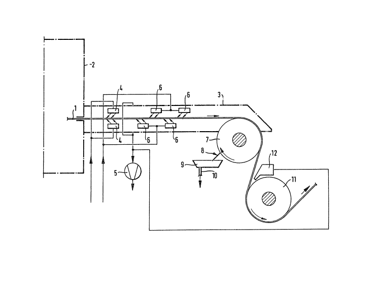
Fi~. 1 shows a schematic layout drawing of an inventive
device equipped with a coolin~ roller doctor blade for
subsequent treatment of a coated OI` printed web.
Fi~. 2 shows a version example of a doctor blade device
in a pivoted position with the blade set on the cooling
roller.
Fig. 3 shows a traversin~ facility for the doctor blade
device in accordance with Fi~
Fig. 1 shows in schematic form a device for subsequen-t
treatment of a coated or printed material web. In this
case, the material web 1 i5 preferably a paper web
printed on both sides which has passed through the
printing units of a roller offset printing machine. The
paper web is subsequently heated in the drier ~. ~uch
driers can be connected to an ex-traction facility used
for removing the solvent vapours which emerge from the
heated ink layer of the printed paper web.
" ` ~L2~ )2~3
A-483
, ~
The paper web passes~through a slot in a wall of the
drier adjacent to the vapour channel 3 and then into the
vapour channel. To prevent large quantities of solvent
vapour emerging out of the drier -through this slot,
blocking nozzles 4 are provided which blow hot air into
-the drier through the slot.
The paper web entering the vapour Ghannel in a hot
condition continues to give off solvent which in part is
e~tracted by the vapour e~traction facility 5. Another
part i5 carried further with the paper web~ on which a
boundary layer of air containing solvent at a relatively
high concentration forms as the resul-t of subsequent
evaporation of solvent from deeper layers of ink.
The solvent concentration of this boundary layer is
partly reduced with the aid of blow nozzles 6 which
direct a flow of blowing air at the paper web essentially
in the opposite direction of movement of the paper web.
A complete "break-up" of this boundary layer is, however,
not achieved in tl~is way so that the ~aper web i8 still
surrounded by solvent vapour as it arrives at the first
cooling roller 7. An air gap forms - intensified by
higher web speeds - between the surface of the paper web
enveloping this cooling roller and the jacket surface of
the coolin~ roller. On the one hand, this impairs the
cooling effect on the paper web so that the temperature
of the paper web in the area of the first cooling roller
is still considerably above the evaporation point of the
solvent; on the other hand this air gap makes it possible
for the solvent vapours contained within it to continue
to diffuse which then collect in -the form of condensate
on the cold surface of the first cooling roller.
In ~E-OS ~3 05 749 referred to in the introduction, an
arrangement is described, in which compressed air i5
blown against that surface of a cooling roller which is
presently not enveloped by the paper web. The purpose of
this measure is evidently to displace the solvent
condensate from the cooling roller and to prevent this
solvent coming in contact with the area oE the web once
again when directed towards the cooling roller.
This is also one of the aims of this invention. The said
pneumatic displacement requires, on the one hand, a
power~ul blower, thereby considerably increasing the
operating costs of a printing machine, and it also causes
an intolerable mist of solven-ts about the printing
machine and its immediate surroundings.
With the invention, however, an arrangement is shown
which prevents harmful solvent vapour from being ~iven
off in the machine and particularly in the machine room.
%~ 02~3
A-4~3
To solve the above m~ntioned task and to achieve the said
advantages, the invention makes use of a doctor blade
device assigned to the first cooling roller which in an
extremely simple yet effective way considerably reduces
the solvent concentration of the ink layer facing towards
the first cooling roller already a-t this coolin~ roller
stage.
With the doctor blade device 8 tFig. 1~ the solvent
condensate precipitated on the first cooling roller 7 is
skimmed off into a collector reservoir 9, from which it
can be drained off in controlled quantities via a
draina~e connection 10.
In this way, the removed solvent is lost in a desirable
way in the further process since it would be otherwise -
without scraping off - carried back by the rotating
coolin~ drum into the said air gap between this roller
and the paper web. This would result in a condensatior. -
difEusion balance forming in the said air gap in
conjunction with a high solvent concentration in -the ink
layer, thereby counteracting subsequent evaporation of
solvents from deeper ink layers. The strand of the paper
web running off the first cooling roller would therefore
- without removal - still have a relhtively high
percentage of solvent in the deeper layers of the ink
layer facing towards the coolin~ roller. For the still
relatively hot paper web this in turn would result in
considerable subsequent diffusion Erom the lower ink
layers alon~ its further path and so that the surface of
the ink: already hardened in the drier would soften once
again. Contact of an ink layer softened in this manner
with subsequent cooling rollers would result in the
formation of ink deposits, initially e~tremely small but
quickly developing and spoilin~ the print format.
In accordance with the invention, a doctor blade device,
functioning as described above, is provided only at the
first cooling roller. ~earing in mind the investment
costs for a printing machine, one of the factors is tha-t
it is necessary to maintain its overall length as short
as possible. This results in short paths of the paper w~b
from the drier to the first cooling roller and,
particularly at high paper web speeds, e~tremely short
periods of time available to the ink to reduce its
solvent content.
On the side of the paper web facin~ away from the first
cooling roller 7 ~Fi~. 1), cooling and evaporation take
place on the one hand without interaction with the
solvent condensate precipitated on the first cooling
0Z8
A-483
roller and, on the other hand, over a longer period of
time up to reaching the second cooling roller 11 (Fig.
1). Corresponding tests have shown that the arrangemeni
of a further doGtor blade device at this second cooling
roller is rendered urnecessary and that in this case to
aGhieve high quality printing results it is sufficient to
provide the known arrangement of suction nozzles 12 ~Fig
1) which have the task of draw off t.he solvent vapours
given off by the surface of the paper web to the
surrounding area.
Fig. 2 shows a version example of an inventive doctor
blade device arranged on the first cooling roller. It
features an interchangeable doctor blade 14 bolted ~olts
13) to the inside of the collector reservoir 9 and which
can be swivelled away from and agai.nst the Gooling roller
7 by a swivel device 16 operated by a control cylinder
15. The contact force between the doctor blade and the
cooling roller can be set at the spring 17 with the aid
of the adiusting nut ~5.
SeGured by means of bolts on the side walls not
illustra-ted and in which the cooling roller 7 is also
mounted are bearing brackets 13 in an opposing
arrangement. The ~earing brackets mount a shaft 19. A
lever 20 and a strip ~1 are secured by means of pins to
this shaEt 19. The lever 20 is moved by the cylinder lS
which in turn can be pivoted about a pin 22 mounted in a
side wall. The strip 21 pinned to the shaft 19 turns -the
cross shaft 23 of a traversing device for the doctor
blade 1~ arranged further below as shown in Fig. 3. The
colleGtor reservoir 9 .is bolted in conjunction with a
connection piece 24 to a swivel piece 26 mounted on the
cross shaft 23 ~screw 27).
A tie rod 28 is attached to the swivel piece 26. With the
aid of this tie rod, the doctor blade is pressed against
the cooling roller 7 by the spring 17 under an adjustable
contact pressure. For this purpose, this spring is
supported on a bracket 29 mounted on the lever 2Q, with
its other end resting against the ad.justing nut 25.
The doctor blade device can be swivelled into position
and away again by the advance and return of the ~ylinder.
When swivelled away, the tie rod 28 is supported on the
bracket 29 by a shoulder 3~.
Fig. 3 shows a traversing device for the doctor blade
device shown in Fig. 2. (Compared to its positions shown
in Fi.g. 2, to provide a more clearly arranged
illustration in Fig. 3, the cross shaft 23, the lever 20,
the swivel piece 2~ and the tie rod 28 are shown in
different angular positions.)
1~4~2~3
A-4
--8 -~
,,
The length of the doctor blade 1~ is defir.ed such that,
when traversing in any of its positions, at least the
jacket area of the cooling roller enveloped by the paper
web is covered. Correspondingly, thi.s len~th is greater
than the width of the paper web by double the traversin~
path.
The traversing movement is provided by means of a
traversin~ cylinder 31 which is mounted between a fork 32
affixed -to the cross shaft and the strip 21. ~To
facilitate clear illustration, in Fig. ~ the fork 32 is
not shown in its actual position with respect to the
cross shaft.) The traversin~ cylinder is actuated by
means of valves and controI lines not illustrated,
whereby the stroke is limited by means of limit switches
33 which are mounted on the cross shaft and interact with
a limit stop 34 linked to the shaft 19.
The cross shaft is mounted in ~earin~ bushin~s 35 in the
strips 21 so that it can be shifted longitudinally. tOnly
one of the two strips arran~ed near the ends of the shaft
is shown.) The swivel piece ~.6 is arranged such that it
cannot be shifted in the lon~itudinal direction of the
cross shaft and is linked to an end of the tie rod 2~ by
means of a connecting rod head 36. The spring 17 fitted
on the other end of the tie rod rests together wi-th a
spherical disc 37 on the bracket 29.
In the position shown in Fig. 3, the tie rod 7.8 pivots
backwards and forwards durin~ traversi.ng in the base of
the spherical ~i.sc 37 at tlle plane of the drawing. The
size of the openin~ 3~ of the bracket for the -tie rod
corresponds to the limit stop of the pivot movement.
In an advantageous version of the invention, the doctor
blade 14 features vulcanized cast elastomer resin i.n the
contact area with the cooling roller 7. This facilitates
a satisfactory service life of the doctor blade. If worn~
doctor blades can be replaced to~ether with the c.ollector
reservoirl facilitated by their detachable screw--typ~
connection. To carry out corresponding service work and
in order to clean the collector reservoir, the entire
doctor blade device can be swivelled away Erom the
cooling roller in the manner described further above. The
collector reservoir 9 can be removed from the machine
after loosening the screws 27.