Note: Descriptions are shown in the official language in which they were submitted.
` -
~ Z 64931-377
Backqround of Inventio~n
The invention relates to weiatherstripping, especially
resilient elastomeric weatherstripping that is used to seal the
doors or decklid openings of automobiles. Such weatherstr.lpplng
is generally comprised of a hollow bulbous portion which acts to
seal the space between the automobile parts, and an lnteigrall~
formed device for holding the weatherstrlppiny in place be~weén
the parts. The stiffness o~ the materlal and the wall thickness,
shape and size of the bulbous portion all affect the closing of
the doors or decklids.
U.S. Patents Nos. 4,263,750 and ~,3~8,443 are typical of
the many patents which disclose a bulbous portion which is hollow
and has an oval or clrcular cross-section that ls lntegral with a
carrier which has angularly disposed tabs of fingers for holdlng
onto a me~al strip to which the carrier is secured. British
Pa~ent No. 2,163,470-A discloses a carrier which is somewhat llke
that of the invention, except that the abutments projecting into
the opening of the carrier are designed to be overrldden hy the
stops which are on the resilient fingers as indicated above. U.S.
Pa~ents Nos. 4rO30~245; 4,114,320 and 4,374,880 disclose similar
bulbous portions and carriers. U.S. Patent No. 2,969,252
discloses a bulbous portion wlth a vent for allowing the
escapement of air from within the bulbous portion as it beco~es~
distorted.
U.S. Patent No. 3,126,590 discloses a refrigerator
gasket which comprises two semi-circular bulbous portions, the
outer portion havlng a thicker sldewall than ~he lower portion to
1 ~ ~
.
6Z
~ 4g31-377
apparently promote bending or collapse of the lower portlon before
the outer portion. U.S. Patents Nos. 2,498,851 and 2,880,049
disclose bulbous portions with uniform thickness walls, so that
bending of a desired area of the seal is probably accomplished by
the shape of the bulbous portion.
The present invention is dirècted to an imp~oved
weatherskrip with good seallng and wrapping around
characteristics.
The invention provides a resllient weatherstrip between
two parts, one of which is stationary and the other of which is
movable in relation thereto, comprising: a~ a hollow bulbous
poxtion for co~pre~sively engaging the movable part as it moves
towards the stationary part, the bulbous portion being mushroom
shaped having cap and stem portlons, the bulbous portion in cross-
section including: I) a cap portion which has an outer surface
which is smoothly curved outwardly a~ay from the stem portion; and
II) a stem portion which has a pair of spaced apart legs ~hich
curve inwardly towards each other from the cap por~ion in a
direction away from ~he cap portion, the legs belng ~hinnect
2Q adjacent to the cap portion and~increasing ln thlckness ag they
extend from the cap por~ion whlch also increases in thickness from
the legs to the peak of the cap portion and which is thicker than
the legs adjacent the cap portion, so that the legs at their:
thinnest portlon will bend more easily than the cap~portion, one
of the legs having at least one aperture thereln for~ allQwing the
: escapement of air from within the hollow bulbouc portton; and b~
means for fastenlng the bulbous po:rtlon to the~ctationary part.
la
~2~ 2
64g31-377
: The invention also provides a reslllent weatherstrip
between two parts, one of which is statlonary and the other of
which is movable in relation thereto, comprising: a) a carrier
for attachment to the ~tationary part, the carrier, in cross-
section, includlng: IJ a generally U-shaped body wlth an open end
in longltudlnal spaced relation ~rom a closed end, and a pair o~
opposing sidewalls extendlng from the closed end to the open end,
II) a pair of abutmen~s projecting ~rom the sidewalls inwardly
towards each other into the space between the sldewalls, the
abutments each having a stop engaging face in spaced relation from
the open end of the body; III) a pair of fingers extending from
the sidewalls~adjacent the open end of the body and inwardly
towards the closed end of the body beyond the abutments and
terminating at free distal ends, the finyers designed to
compressively engage therebetween, a flange of the stationary
part; IV) a pair~of stops at the free distal ends of the fingers
for engaging the abutments when the carrier is mounted on a flange
of the stationary part and the carrier attempts to~leave the
flange; the abutments and stops having engaging faces which are
substantially parallel to each o~her and normal to the
: longitudinal axis of the space between the sidewalls to provide a
positive interlock between the abutments and the stops; and b) a
hollow bulbous portion extendin~ ~rom the carrier for
compres~ively engaging the movable part when lt moves toward the
stationary part.
DescriPtion of Drawin~
The following description of the invention~will be
:
lb ~ .
: , - ~. ' ' ~ ' ' ~ , ', ' ,
- .
gLZ8~62
6~931-377
better understood by having re~erence to the accompanying drawlng,
whereln:
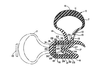
Fig. 1 is a section o~ a weatherstrlp whiah is made in
acaordance with the invention;
Fig. 2 is a simLlar section showing the seallng actlor
of ~he weakherstrip with an automobile door and
Fig. 3 is a similar seation showiny the wraparound
effect of the
lc
~'' ~ . :
- , .. . . :
, ~ ;! . '
1 X 8 9L~L6
bulbous portion of the weatherstrip and the retention of the carrier o~
the weatherstrip.
Detailed Description of Drawing
With reference to Figs. 1-3, there is shown an elongated weatherstrip
or seal 5 wh;ch, in this instance, is designed to be mounted around a car
door opening to sealingly engage the car door 6 when it is rotated t~ a
closed position. The seal 5 is composed of any suitable, resil~ent, elasto-
meric material, e.g. rubber. The seal 5 comprises a hollow, b~lbous por-
tion 7 which extends from a carrier port;on 8 which is secured ko a ~lange
9 of the car frame and holds the bulbous portion 7 in place for eng~ging
the car door 6. The bulbous portion 7, shown in dotted line of Fig. 1, is
positioned on the carrier portion 8 to engage an adjacent decklid 10, if
such is desired.
The bulbo~s portion 7, in cross-section, is mushroom-shaped having an
outwardly curved cap 11 and a stem 12 that consists of two separate legs
13~ 14 which curved inwardly towards each other from the cap 11 to the car-
rier 8 and which increase in thickness as they approach the carrier 8. A
plurality of similar apertures 15 are placed in the inner leg 13 closest
the car frame, to allow the escapement of air from within the hollow bulb
7 to facilitate collapse of the bulb 7 and closing of the car door 6.
The cap 11 increased in thickness from the legs 13, 14 to the peak 16 of
the cap 11 midway between the legs 13, 14. The cap 11 is thicker than the
legs 13, 14 of the stem 12, adjacent the cap 11, especially at the peak 16
of the bulb 7, i.e. the part of the bulb 7 farthest from the carrier 8.
As seen in Figs. 2 and 3, the complete collapse of the cap 11 will not af-
fect the aperture 15 which, in some prior art seals, will close upon col-
lapse or distortion of the bulb.
The carrier 8, in cross-section essentially comprises a U-shaped body
16 with an open end 17, and a mechanism l~ for compressively engaging and
holding the flange 9 of the car frame, when the carrier 8 is mounted on the
flange 9. A U-shaped piece 19 of metal is embedded in the body 16 to rein-
force the closed end 2Q and opposing, parallel sidewalls 21, 22 of the car-
rier 8. A pair of oppositely disposed abutments 23, 24 project from the
sidewalls 21, 22 inwardly into the longitudinally extending space or opening
25 between the sid-ewalls 21, 2? in spaced relation from the open end 17 of
the carrier 8. A pair of resilient fingers 26, 27 extend from the sidewalls
21, 22 adjacent the open end 17 inwardly towards the closed end 20 beyond
the abutments 23, 24 to compressiYely engage the ~lange 9 of the door ~rame
:
~. ,
.. . . . ,. -
- ~
--3--
as the carrier 8 is mounted on the flange 9. A pair of stops 28, 29 are
provided at the free distal ends 30, 31 of the fingers 26, 27 for inter-
locking engagement with the abutments 23, 24 should thé carrier 8 attempt
to pull away or escape from the flange 9, as seen in Fig. 2. The flange 9
pushes the fingers 26, 27 apart as it enters the opening 25 to bring the
stops 28, 29 into alignment with the abutments 23, 24. Note that the en-
gaging faces 32, 33 and 34, 35 of the abutments 23, 24 and stops 28, Z9,
respect;ve1y, are substantially paralle1 and at r~ght angles to the longi-
tudinal axis of the opening 25 to provide a positive interlock between the
abutments and stops and a tighter gripping action of the mechanism 18.
Thus, there has been described a mushroom shaped bulbous portion which
is integrally formed with a carrier which is provided with a pair of fing-
; ers for firmly gripping the flange of a car frame on which the carrier is
desired to be mounted. The mushroom stem or legs for holding the mushroom
cap are purposely made narrower where they engage the cap~ so that they,
and not the mushroom cap will initially deflect and become distorted uni-
formly under the cap, which, upon further compression, will be resisted by
the substantially upright parallel legs in much the same way that a weight
lifter's extended arms press weight to protect the seal from severe dis-
tortion and possible ruination. The mushroom cap has good wraparound char-
acteristics, as shown in Fig. 3 of the drawing, because of the ease at
which the resilient legs of the stem will adapt to forces imposed on the
cap.
,
.