Note: Descriptions are shown in the official language in which they were submitted.
.~
62~06-80
RAISED DEPRESSIBLE PAVEMENT HARKER
Backaround and Summarv of the Invention
This lnvention relates generally to ralsed pavement
markers which are embedded in pavement and more particulary
relates to a ralsed marker which is depressible when struck by a
passing snowplow or wheel and is provided with a spring return
means which addltionally prevents freezing and inhibits
contamination of the marker.
A1BO disclosed are self illuminating and locational
pavement markers for use in marking roadway surfaces.
A serles of traffic markers are often spaced along
roadway for guldlng vehlcles lnto orderly lanes ln order to create
efflclent trafflc flow patterns and malntaln a safe spaclng of
vehlcles. Typlcally, the markers are embedded in or otherwlse
secured to the 6urface of the pavement and have a portion whlch
protrudes upwardly above the pavement. Thls protrudlng portion
carrles a reflector sufficiently above the pavement so that rain
water wlll not cover the reflector.- Thls allow~ llght from
vehlcle headllghts to be reflected back to the drlver maklng the
marker~ clearly vl~lble. Thi~ protru~lon above the pavement
~urface also enhances the safety features of the marker because a
longltudlnal serle~ of such markers wlll cause a serles of
thumplng vlbratlon nolses whlch are both heard and felt by a
drlver and therefore provlde a warnlng lndlcatlon to the drlver
that he has strayed from the proper course.
Although such elevated markers are deslrable for the
~P
62406-80
above reasons, it must~be accomplished with a structure whlch will
not cause damage to a vehicle or which i~self will be damaged in
the ordinary course of its use. It i~ desirable that, neither
tlre da~age nor
,: '
','~
. ~ :
.~"
, ,,
,,, . ~:,
~:: ~ .,
, ~, ~ , . . .
~ , . ~ ,.
.: .
....
.
- .
.,. : :.
- 128~283
~, ~.
marker damage should occur when the marker is driven cver by a
vehicle.
Purtherm~re, in those regions where ordinary winter
snowfalls require periodic scraping of the highway with a scraper
blade, the scraper blade should not damage the protruding marker. m e
marker should be able to withstand regularly repeated blows by the
snowplow blade without any damage to the marker or any detrimental
effect upon the snowplow itself or upon snowplowing efficiency.
As a result of these needs there have been a variety of
designs of retractable markers. The retractable marker, although it
p~otrudes above the highway also may be depressed by the incident blow
of a snowplow blade or vehicle tire. Iypically, a bsveled upper
~urfa oe formed on the protrusion provides an inclined plane across
which the blade or tire rides deflecting the protruding portion of the
marker downwardly to its withdrawn position.
A variety of different markers have been shown in the prior
art. Some depend upon the flexing of a portion of the marker
structure to permit the deflection and withdrawal of the protruding
portion of the rarker. Unfortunately, w ch flexing over a period of
t~e and uFon exposure to the deteriorating effects of ~unlight has a
tendency to cause cracks and breakage eventually resulting in the
total destruction of at least the FnoCruding portion of the marker.
A~ ~ result, the cylinder ~nd pi~ton-type markers are
preferable ina~much as they can be rigidly and strongly constructed,
do not depend upon the flexing of exposed nater~als and still provide
the advant~ges descr~bed akove. ~hey have, however, suffered from the
difficulties that a cavity or void is of rece8sity formed within the
cylinder and beneath the piston into which the piston moves when
~2B4283
depressed by a vehicle tire or snow~low. Unfortunately, the cavity is
subject to the collection of rainwater or snowmelt water and
subsequent freezing on cold days or nights. Such freezing of
accum~lated water may render the piston-type unit inoperable. The
piston cannot be ~oved downwardly into a space occupied by ice and
thus it may be destroyed as a result of snowplowing operations. The
inclusion of relatively large voids within such a marker and the
resulting formation of relatively thick i oe masses also can cause
structural damage to the marker as a result of expansion of the
freezing water.
In addition, piston-type markers have interfacing, sliding
surfa oe s between the piston and cylinder which are subject to the
oollection of highway dirt and grit which can hinder the retraction of
the piston. The cavity below the piston also can collect dirt or
~olid particul~te matter which will produce the same effect as i oe .
m e d~rt is collected because each time the piston is depressed, air
is exhausted from the cavit~ and then when the piston is released,
air-borne or wa~er-borne highway dirt is inhaled into the cavity.
In addition, roadway mar~ers ~qo~ in the past have generally
keen reflectorized and not aelf-illuminating which would be
advantageou6 in certain applications. Illuminated markers of the
pa~t, ~uch a6 tho6e u~ed at alr prt6, require ~one type of power
sour oe ffuch a6 an urdergT~und inter~Qnnect1ng wiring system. m is
reqo1rement, which may ~e suitable for relatively ~hort road nurfa oe s
uch as air strips where power and/or regular maintenan oe $s readily
av2~1able, has nct been generally aooepted or adopted for general use
on h~ghways or other general road surfa oe $nstallat$ons. In addition,
these markers may requ~re $nstallat$on at the time of oonstruction of
- 3 -
.
" ' ' : -.. :- ' ,....... .
1~2~2B3
the roadway because of the installation of wiring which may be
necessary to institute such a system.
Location markers have also beccme common along mndern
roadways. m ese locational markers are commonly known as "mile
marker" signs which are placed at one mile intervals along the
roadway. These locational markers allow a mDtorist or emergency
vehicles to ascertain their approximate position along the roadway.
Hawever, in order to take advantage of these markers the motorist must
be able to see the roadway marker. Generally, this is not a problem,
but a motorist who has car trouble may not be able to take advantage
of the markers to locate his position unless he is within sight of the
~ign. Also the necessity of these markers alone adds increased
clutter to the roadways and increases naintenance costs for
replaoe~ent of the signs subsequent to accidents or as a result of
environmental deterioration.
m ere i6 therefore a need for improvements in the
piston-type traffic marker which can overcore the above problems.
Accord~ng to the pre6ent ~nvention there is provided an
improved, depressible, reflective traffic marker. ffl e traffic marker
includes a base receptacle ~dapted to ke ~ecured within a cavity
formed in a pavement or roadway surface. A piston is moveably disposed
within the ~ase and has a portion which normally p¢otrudbs above the
ba~e and tbe pavement surfaoe . m e piston oontalns reflector surfa oe s
appropriately oriented relative to the traffic lanes and is
resillently depressible dcwnwardly into the base. Also provi W i6 a
resilient, oompres6~ble, s~bstantially water impervious ~ass which
~ubstantially fills all the space within the base and the interior of
the piston assembly so as to prevent accumulations of water as well as
\ ~
62406-80
to resiliently bias the piston upwardly so lt protrude~ above the
pavement surface and base receptacle.
While the plston is designed and constructed in such a
manner as to resist damage from vehlcles, plows, etc. for an
extended period of time, the depressible marker of the present
inventlon is designed to enable quick and easy replacement of the
piston should damage thereto impair its operational effectiveness.
Thus, the present invention provides a highly durable,
relatlvely inexpensive depressible pavement marker whlch may be
easily and qulckly lnstalled in existlng roadway surfaces and is
partlculary well suited for use ln climates requiring frequent
clearin~ of snow therefrom.
In ~ome appllcatlon~ lt 1~ dlfflcult to posltion
reflectors provlded on such pavement markers as the present
lnventlon ~o as to be totally effective ln returnlng ligh~ to the
vehlcle operator such as for example along a bend in a highway.
Addltlonally there exlst many other appllcations where lane
markers may be deslrable but an adequate source of llght is not
avallable to render reflectors effectlve. Por such appllcatlons
there 18 aleo dlsclosed a self-lllumlnatlng retractable traffic
marker. Thl~ marker also includes a base receptacle and a
depres~lble pl~ton. The pl~ton lncludes a self contained llght
~ource and a power source such as a rechargeable battery for
powerlng the llght. A solar cell may be openly posltioned on the
pl~ton for recharglng the battery from avallable sunlight during
dayllght hours. A sultable photosensltlve switch means is
62406-80
provided which responds to ambient light levels so as to activate
and deactivate the internal light source between night and
daylight hour~ respectively.
In some other applications, it may be desirable to
incorporate means to advise emergency or police vehicles or the
like of their present location. Accordingly in yet another
embodiment disclosed herein, a suitable transmitter may be
provided capable of transmitting a suitably coded signal which
upon receipt by a suitable vehicle mounted decoder may advise the
operator of the precise present location of the vehicle. Such
device~ could be extremely useful to police and other emergency
vehicles as an ald ln provlding servlces to accident scenes or the
llke or even on broad computer tracking systems presently being
con~ldered for lncluslon in vehlcles of the future.
It is an ob~ect of the present invention to provide a
depres#lble marker whlch is lmpervious to the elementæ normally
encountered on a roadway surface and ls effectively able to resist
damage re~ultlng from snow removal vehicles.
It i~ a further ob~ect of the present invention to
provlde a replaceable pl~ton a~sembly for slmplifled replacement
of a roadway marker.
According to a broad a#pect of the invention there is
provlded a depreæslble, reflectlve, pavement marker comprlslng-
a ba~e receptacle adapted to be flxedly secured to the walls
of a cavlty formed wlthln a pavement, sald base receptacle havlng
an upper end portion adapted to be positioned at or below the
..C
62406-80
upper surface of said pavement whereby snow removal equipment may
move thereacross without damaging said receptacle;
a piston assembly freely movable within said base and
including a reflector, portions of said piston assembly normally
protruding above the base and the pavement surfa~e, said portions
being depressible downwardly into sald basq;
a resilient, compreseible, substantially water inpervious
mass filling substantially all the space wlthin said piston
a~sembly and wlthin said base and biasing said piston assembly
upwardly to protrude above æaid base t said mass minimizing void
~ace ln ~aid plston assembly and said base to effectlvely inhibit
accumulatlon of water therewlthln wlthout requlrlng rellance upon
~ealing mean~ operatlng between sald plston and said receptacle
whereby pl~ton movement preventlng lce formatlon withln said
chamber is effectively re~isted and movability of said piston
withln ~ald chamber i8 malntained without regard to ambient
cllmatic conditlon~.
Accordlng to another broad aspect of the inventlon there
1~ provlded a depresslble pavement marker comprlslng.
a ba~e reaeptacle adapted to be flxedly secured wlthin a
cavlty formed ln a pavement, ~aid receptacle having sidewalls
de$1nlng a chamber open at the top thereof;
a plston member slldably dlspo~ed withln said ba~e receptacle
and havlng dependlng sidewalls posltloned ln closely oppo~ed
slldlng relation~hlp wlth said base ~ldewall~ to guide movement of
~ald piston wlthln said chamber and including an outwardly
6a
~2E~
62406-80
projecting portion normally extending above sald pavement surface;
light directing means carried by said outwardly projecting
portlon of ~aid piston;
cooperatlng means provided on said piston and said base
receptacle to allow substantially free sliding movement of said
plston within said receptacle between ra~sed and depressed
positlons;
a resilient compresslble substantially water impervious mass
filllng substantlally all of the remalning space within said
chamber, said mass being operative to bias said piston member
outwardly from ~aid receptacle, sald cooperatlng means belng
operative to limit outward movement of said plston member, sald
mass belng urther operatlve to effectively inhiblt accumulation
of water within said chamber whereby piston movement preventing
lce formatlon within sald chamber is effectively resisted and
movement of said piston wlthln sald chamber ls malntalned without
regard to ambient climatic conditions;
releasable retalning means operable between said piston and
said receptacle, said retainlng means cooperatlng with said
cooperatlng means to prevent relative rotational movement between
said piston and said receptacle to enable removal of said piston
from said receptacle through said open top thereo~.
According to another broad aspect of the lnvention there
is provided a depressible pavement marker comprlsing:
a base receptacle adapted to be fixedly secured within a
cavity formed in a pavement, said receptacle having sidewalls
6b
62406-80
de~ining a chamber open at the top ~hereof, said base receptacle
having an upper end portion adapted to be positioned at or below
the upper surface Qf said pavement whereby snow removal equipment
may move thereacross without damaging said receptacle;
a piston member slidably disposed within said base receptacle
and including an outwardly projecting portion normally extending
above said pavement surface;
llght directing means carried by said outwardly pro~ecting
portion of said piston;
:1~ cooperating means provided on said piston and said base
receptacle to allow substantially free sliding movement of sald
piston within said receptacle between raised and depressed
positions;
a resilient compressible substantially water impervious mass
filling substantially all of the remaining space within said
~hambar, said mass being operative to bias said piston member
outwardly from said receptacle, said cooperating means being
operative to limit movement of said piston member, said water
impervious mass mlnimizing void space in said piston and said base
~a t~ effectively inhiblt accumulatlon of water within said chamber
without reliance on sealing means operating between sald piston
and sald receptacle whereby piston movement preventing lce
forn)ation within said chamber is effectively resisted and
movability of said piston within said chamber is maintained
without regard to ambient climatic conditionæ.
6c
l`Z8~83
, ~
Brief Description of the Drawings
Other advantages of the present invention will be readily
appreciated as the same becomes better understood by referen oe to the
following detailed description when considered in connection with the
accompanying drawings wherein: .
Figure 1 is a perspective view of the raised depressible
pavement marker of the present invention;
Figure 2 is a section view of the pavement marker shown in
an $nstalled relatianship to a paved surfa oe , the section being taken
along line 2-2 of Figure l;
Figure 2a is a fragmentary section view similar to that of
Figure 2 bu~ ~howing the pavement marker in the depressed position;
Pigure 2b is a scaled down detailed section view of the kase
recepkacle of the present $nvent$on showing the slot arrangement in
the base reoeptacle, the sect~on being taken along line 2k-2b of
F$gure 3;
Figure 3 is a top view of the pavement marker of Fig~re l;
Flgure 4 i~ ,a ~ec*ion view of the pavement narker of the
present ~nventian, the ~ection being taken along lines 4-4 of Figure
Figure 5 is a top view of the piston a~sembly in accordan oe
with the pre~ent invention;
Figure 6 18 a ~ectional view of the piston a~serbly of
Figure 5, the section being taken along line 6-5 thereof;
Figure 7 i~ an enlarged fragmentary 6ection view showing the
~edge and reflector as~embly in the piston asse~bly of the pre6ent
invention;
~2~
62406-80
Figures 8, 9, 19, and 11 are detailed views of the wedge
used in the present invention;
Figure 12 is a detailed plan view of the glass reflector
used in the present invention;
Figure 13 is an edge view of the glass reflector of
Flgure 12;
Figure 14 is a fragmentary section view of the pavement
marker of the preæent invention showing the elongated locking
splke used in the present invention;
Flgure 15 is a plan view of the elongated locking spike
of Flgure 14;
Flgure 16 is an edge view of the elongated locking splke
of Flgure 14;
Flgure 17 is a perspectlve view of one embodiment of the
reslllent compre~ible water lmpervious mass of the present
lnventions
Figure 18 is a peræpective view partially in cross-
section showing an alternate embodiment of the resilient
compresslble water impermeable mass of the present inventlon;
Figure 19 is a perspective view in cross-section of a
further embodiment of the resilient compressible water impermeable
ma~s of the pre~ent invention;
Figure 20 iB a perspective view partially broken away
showing a self-illumlnatlng marker;
Figure 21 ls a perspective view illustrating a
locational pavement marker installed on a roadway surface; and
.~
;L2~3
62406--80
Figure 22 is a fragmentary perspective view partially
broken away showing the embodiment of the locational marker of
Fig~re 21.
8a
6~"^1
~J
~:28~3
. ,
escription of the Preferred Embodlm.=ts
m e raised depressible, reflective pavement marker of the
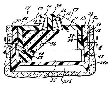
present invention is generally shown at 10 in Figure 1. As shown in
Figure 1 the pavement marker comprises a base reoeptacle 12 and a
piston assembly 14 which houses a reflector assembly 16. Ihe base
receptacle 12 is generally cylindrical in nature and includes gripping
surfaces 18 to allow the unit to be gripped by an installation machine
when installing the marker in a pavement surfaoe 26. ~he base
receptacle 12 includes a conical portion 24 at the lower portion
thereof and acts as the supportin~ skirt for the marker 10. As shown
in Figure 2 the portion 24 defines an outer 6upporting sXirt portion
24a and a hollow central portion 24b. This hollow oe ntral portion 24b
is particularly de~irable on markers to ~e pla oe d in concrete roadway
~urfa oe s in order to acoommodate an uneven broXen surface which often
results from the hole forming coring or drilling operation on concrete
road surfa oe s. In those applications where the marker is to be
~nstalled in other types of road surfa oe s wherein it is more readily
poss~ble to obtain a relatively ~m~oth bottom ~urfa oe in the drilled
hole, the bottom surf~ce of base ~cyL~cle will preferably be
rel~t~vely planar with no hollow area 24b. ~he base receptacle 12 has
an inner wall 34 defining a cylindrical cavity ~o~ded by the wall 34
uld bottom ~urfaoe 35.
A pair of sub~ntially vertical elongated l;lots are forned
in wall 34. The slots 22 are vertically di~posed along the length of
the wall 34 on di~metrically opposed ~ides of the wall 34 and open
outs~ardly from tcp 20 of the base. Referring now to Figure 2b the
slot~ 22 include a thin portion 41 and a lawer wider portion 42
formi ng an elongated "L" ~hape which defines a cir~mferentially
_ g _
1284Z83
~ ,
extending shoulder portion 40. A radially extending shoulder 39 is
also formed at the top of portion 41.
The base receptacle 12 is integrally molded as a one-piece
assembly in the preferred embod4nent of the invention. Hbwever, the
base receptacle can also be produced as a two-piece assembly with the
lower conical portion 24 and the main cylindrical body portion
produced in separate operations and asse~bled together with suitable
adhesives or fasteners to provide a watertight seal. me base
receptacle 12 is preferably made from a suitable high strength
polymeric composition such as a polycarbonate structural material.
Hbwever, the receptacle could be made out of any other suitable
materlal such as ~etal, ceramic, other poly7neric materials or the
like, which can withstand the oonditions incident with being ~cunted
in a pavement surfaoe and the repeated shocks from passing traffic.
Referr~ng to Figures 2, 5 and 6, the piston assembly 14 of
the pre~ent $nvention has an up~er protruding portion which houses a
reflector as~embly 16. Incl$ned ramp surfa oe s 57 are provided to
protect the reflector assembly 16 L ~.. direct blows LY~I~ a snowplow
blade or the like. m e ramps 57 lead to a relatively flat top surfa oe
59 which is ~trenqthenei by $ntegral rib 66 which runs perpendicular
to the ramps 57. Ramps 57 are reinforoed by wear m~mbers 58, 59, 60,
and 61 which are enkedded in the piston assembly just below the outer
~urfa oe thereof. m e wear memker~ may be made of any wear resistant
material such as ~etal and are preferably a series of stainless steel
wires which are integrally molded wi~h$n the piston ~ssembly. The
piston assembly also includes a piston wall 32 which is cylindrical
and further defines a cavity by way of its inner walls 31. m e piston
wall 32 includes radially outwardly extending locking tangs 38.
-- 10 --
- lZ84283
~ eferring now to Figure 7, the reflector assembly 16 is
securely held in place in the piston assembly 14 by way of backing
wedges 62 and 64, which support the reflector assembly by
corresponding engagement of bearing surface 63 with the oentral rib 66
of the piston 14. m esé wedges may be oe mented into position or
otherwise attached between the reflector assembly 16 and the oe ntral
rib portions 66 to structurally strengthen and support the reflector
assembly 16. Alternatively, it may be possible to emked the reflector
assembly 16 in the piston assembly prior to complete solidification of
the molding material or even d~uring the molding operation thus
el~minating the need for the backing wedges.
As ~hown in Figures 12 and 13, the reflector assembly
ccmprises a tempered gla5s or other hard nurfa oe d abrasion resistant
outer member 67 which is backed b~y a reflective surfa oe member 68
facing the abrasion resistant memker 67. The reflective surface
nember 6B can be of any of the oommercially available reflectors
produced today. In a preferred cntodiment the material is a metal
foil-like material which has a reflectarized surfa oe and is secured to
the tempered glass 68 with the reflecborized surfa oe facing cutwardly
through its transparent glass ~urfa oe . It is readily appreciated the
reflector a~sembly 16 may be colored ~nd have an advantageous oDlor
~cheme ~uch as, a red reflector on one side ~nd a green reflector on
the other side, or other colors as mlay be desired in the particular
application.
Referring ncw to Figure 17, the mass 36 ~ay ~ ~,ise a pair
of elasbo~eric discs 44 and 46 which are resilient, ocTpressible and
wQber impervious. The cmbodl~cnt of Figure 17 allows the csvity to be
~ubstantially filled by discs 44 and 46 and is advantageous in that
;283
the manufacturing of a pair of such disks would be easier than
attempting to produce a one-piece article of the sa~e shape.
Referring to Figure 18, in an alternate en~cdiment the mass
36 is a bladder 48 which has an elastomeric skin and is filled with a
compressible substance such as air. In the alternative the bladder
can be filled with any type of foam material which is resilient and
compressible. At least the skin of the bladder 48 must be water
impervious for advan.ageously functioning in the present invention.
In Ad~i tion, a foam may be used which creates its own water
~mpermeable outer layer during molding even if the inner foam material
is not of the closed cell type.
In a third and preferred en~cdiment of the present invention
the mass 36 includes a helical spring SO which i8 integrally molded
within a water impervious oompressible and resilient elastomeric
material. As shown in Figure 19, spring 50 ig provided which is
integrally molded within the closed oe ll elas eric material to
provide assistance to the resiliency of the mass 36. m e en~odiment
o maRs 36 ~hown in Figure 19 i5 particularly advantageous should the
piston 14 be held in a compresged position for a period of time. If
this condition ~hould occur it iR known that some elastomeric
~ater~als will take a permanent set if a foroe is applied to them for
a sufficient period of tim0 and may take an inordinate amount of time
to return to their former un~ LeRsed position or may not return to
the prior positio,n at all. m e spring 50 w~uld help to reinfor oe the
resiliency of the material under ~uch oonditions to return the piston
to its normally pootrud1ng position.
Mass 36 substant;Ally fills the cavity foDmed between the
piston and the remaining lower portions of the receptacle base. The
- 12 -
~2t3~8;~
~ass 36 is made of a resilient, compressible, and substantially water
impervious material which is oompressible upon a downward for oe on the
piston assenbly 14.
m e mass 36 is preferably an elastomeric material such as a
closed cell foam material which is shaped to substantially fill the
cavity between the piston and the receptacle base. Eecause mass 36
substantially fills the cavity formed between the piston assembly 14
and the base 12, there is substantially no EFa oe where ex oe ss water or
air oould ke retained. Thus, ~nn~ normal cycling of the piston into
the base receptacle substantially no water or air is externally
displa oe d uFon downward pressure and likewise when the piston returns
bo its normally protruding position ~ubstantially no air or water can
enter the cavity because of the presence of the ~ass 36. Mass 36 is
compressed and expanded with the oycling of the piston and hence
oontinuously fills virtually the entire ~pa oe ~ring this cycling.
m is oonfiguration provides the advantage of not allowing an inhaling
~nd exhaling of water and silt materials which oould hinder the
functioning of the retractable marker or oould dsmage the marker such
as if water would remain in the internal co~ponents and freeze. Thus,
with the mass ~ubstantially filling the qpa oe ketween the piston and
the base water c~nnot be reta~ned by the base. The oonfiguration of
the pre~ent inventlon allows a car or ~nowplow blade to break any thin
layers of i oe which may remain between the base wall 30 and the piston
wall 32 ~nd will continue allowing retractability e~en in the m3st
~dver~e coHditioos.
The material of mass 36 ~ust be resilient such that it will
act to bias piston 14 upward and can be ocn~3ressed but will return to
it original oonfiguration. In addition, the mass 36 should be
- 13 -
_~ r ~ 12842~33
compressible such that it can be oompressed to a smaller volume than
in its origi~al noncompressed position. m is allows the mass to
substantially fill the space lying between the piston 14 and the base
12 displacing water from the space. m e mass should also be
impervious to water so that it will displace water.
In the preferred embodiment of the invention a relatively
stiff but resilient closed-cell foamed resinous material is used,
however, other materials which include the above advantageous
characteristics could be used without deviating from the scope of the
present invention.
The piston assembly 14 generally operates as a piston within
the receptacle base 12. A portion of the piston assembly 14 generally
Fr~n~les above the tcp surfa oe 20 of the Sase re oe ptacle 12 and
surrounding pa~ement ~urfa oe 21, such that the reflector 16 is
po~itianed above the pavement surfa oe and is visiblé to onccming
traffic. Slots 22 oorrespond to retention tangs 38 on the piston
aRsembly 14 which allows the piston assembly 14 to be installed in or
renLved from the base recepkacle 12, as more clearly set forth below.
Referring now to Figure 2, the marker of the present
invention i8 installed in a pavement surfa oe 26 by first drilling a
~uitable bore 28 in the p vement surfa oe . me unit i5 then mounted
into the bore 28 ~nd a ~uit~ble adhesive 30 such as an epoxy oompound
is used to fill the gap between outer surfa oe of the base receptacle
12 and the Sore 28. Thus the marker is ~dhe6ively secured within the
bore 28 by the epoxy oompound and is al60 mechanically held in
positian due to the outw3rdly flared oonical 6hape provided on the
lower ba6e portion 24. It should be noted that the radially outwardly
flared lower port$on 24 of base 12 also perfonms the function of
- 14 -
lzs~a3
maintaining a relative seal mg relationship with the sidewalls of bore
28 so as to restrict and minimize the possible flow of adhesive 30
into the area below marker 10 which could cause marker 10 to float
upwardly sonewhat during the time required for the adhesive 30 to set.
As shown in Pigure 2, piston assembly 14 includes
cylindrical piston wall 32 which cooperates with wall 34 on the base
receptacle 12 forming a piston-in-cylinder arrangement whereby the
piston assembly 14 is retractable or depressible into the base 12.
The mass 36 is plaoed between the piston assembly 14 and base 12 in
the cavity fonmed therebetween. m e mass 36 is shaped so as to
Eubstantially fill the entire cavity formed between pistan asse~bly 14
~nd base 12 when the piston is in its uFperm~st extended position as
~hown in Figure 2. m e walls 32 and 34 are circularly symmetrical
~round a oommon axis in the preferred embodiment of the invention.
m e piston 14 is biased upwzrd by the mass 36. Retention
tangs 38 on the piston 14 cooperate with shoulders 40 fonmed in the
base receptacle 12 to ~top or limit the uFward ncvement of the piston
and to position the piston 14 at the desired p50trudlnq position above
the pavement 6urfaoe as shown in Fig~re 2. A wider pontion 42 of slot
22 is provided in the base reoeptacle 12 which allows ~angs 38 to n~ve
in a downward direction upon receipt of a dbwnward for oe on piston 14
for instance fr~.. a cir tire or a ~nowplow blade. Cooperation between
slot 42 ~nd retention tangs 38 also acts to prevent rotation or
misalign~ nt of the piston in an undesired direction. As best shown
in Figure 2a, downward pressure on piston 14 causes tangs 38 to move
dbwnward along ~lot 42, compressing the mass 36 and ~llowing the
6n4wplow blade or vehicle wheel to pass over the piston 14 wlthout
incident or dbnage to either the vehicle or the piston 14. Upon
- 15 -
1284283
,. ~,~
release of the downward force the resilient mass 36 returns the piston
to its normally protruding position as shown in Figure 2.
In the preferred embodiment of the present invention the
piston assembly 14 is selectively remDvable from the receptacle base
12. Referring now to Figures 3 and 4, the retention tangs 38 of
piston 14 correspond to the slots 22 in the receptacle base 12. Upon
installation the piston is displaced dcwnward with tangs 38 riding
downward along slot 22 until reaching the circumferential shoulder 40
which leads to slot 42. me piston is rota W along the
circumferentaal shoulder 40 until reaching slot 42 where it is
restrained from ~cving uçward by the shoulder 40 as shown in Figure 2.
ILcking spike 52 is provided which is inserted into and retained in
~lot 22 to pr~vent circNmferential movement of tangs 38 of piston 14.
Referring to Figures 14, 15, and 16, elongated locking spike 52
lncludes lip 56 which engages and retains the spike 52 in slot 22 by
engagement with the radial shoulder 39 of slot 22 as shown in Figure
14. As locking ~pike 52 essentially fills the spa oe defined by slot
22, reverse rotation of tangs 38 is effectively prevented. Hbwever,
shculd for some reason it beoome w es a ry, piston assembly 14 and/or
mas~ 36 may easily ~nd oonveniently be replaced by first removing
reqpective lodking ~pikes 52, rotating piston as~embly slightly and
withdrawing it fnom base 12.
Thus, there is provided by the present invention a p ve~ent
marker in which the kase receptacle 12 could be in6talled initially in
the pavement and piston assembly 14 installed later or in which the
piston 14 oould be replaoed on an as needed basis. This pr3vides a
oonvenient oonfiguration so that if a refl~ctor iB damaged it can
easily be replaced. In addition, sh3uld it be oonsidered advantageous
- 16 -
r - ~
.lZBg283
62406-80
to replace a piston having reflectors of one color with a piston
having reflectors of another color or with a piston having other
features, the piston could be easily and conveniently changed
wlthout removing the base receptacle from the pavement.
The piston assembly 14 is constructed to include ramp
surfaces 57 which allow the snowplow blade to depress the piston
14 and serve to guard the reflector assembly 16 from shattering
lmpacts To further toughen the structure and prolong the life,
stainle~s steel reinforclng wires 58, 59, 60, and 61 are provided
a~ ~hown in Figures 5 and 6 thus even if the plastic material of
ramps 57 is worn away or otherwise damaged by continual impacts of
snowplow blades the ~tainle~ steel wire~ will remaln to provide
ramp surfaces whlch would protect the reflector assembly 16 from
#hattering impacts prolonging the useful life of the piston. In
addltlon, the reinforcing wires will act to strengthen the
constructlon of the plston assembly.
Referring now to Figure 20, there is shown a marker 70
whlch lncludes a self-lllumlnatlng feature. Thls marker may be
used where lt i~ deslrable to have an actual illuminated marker,
such as ln alrport appllcations or on roadway curves, where it may
be partlculary de~lrable to have the road surface marked by a
llghted rather than a reflectorlzed marker.
The self-lllumlnatlng marker generally shown at 70
lncludes light source 72 which ls placed behind the tempered glass
74 for lllumlnating the marker at night. Also included in the
marker is a solar cell 76 and rechargeable battery 78. A sensor
17
~ .
. .
.~ l'Z8~283
62406-80
79 is also provided which actuates the light source 72 upon
receiving an external indlcation or signal.
The solar cell operates to recharge the rechargeable
battery 78 during daylight hours. Upon darkening light
conditions, the sensor 79, which in this embodiment includes a
photocell type switch, operates to switch on the light source 72
and ln turn swltches the light source off during daylight hours.
Thus, there is provlded a self contained unit which automatically
operates to mark the roadway surface durlng low light conditions
and i~ sel~ actlvating and requires low maintenance because lt
recharges itself.
In an alternatlve embodlment the sensor 79 may include a
receiver switch which responds to an external radio signal to turn
on the light 72. Thus, it may be partlculary deslrable to use the
pavement marker of thls embodiment ln a remote airstrlp where it
could be illuminated upon demand only when needed. In addition, a
transmltter ln a plane or an automoblle could automatically turn
on the reflector when lt came lnto close proxlmity of the marker
and could operate to turn off the marker after passlng the marker
or when the marker is no longer needed thus saving the electriclty
in the rechargeable battery. Thls embodlment could also be
advantageous ln provldlng a safer conditlon for partlcular
appllcatlons, such as ln low trafflc curved areas where a llghted
marker is only necessary when a vehlcle traverses the curve. The
battery, solar cell, and sensor may all be contained in the piston
of the marker and thus thls type of marker could be used as a
18
~3
6~406-80
replacement for a reflectorized marker piston, using the base
which is already installed in the pavement.
Referring now to Figure 22, there is illustrated another
embodiment of a locational pavement marker generally shown at 80.
This marker may contain the features of a rechargeable battery,
solar cell, light source, as disclosed above. In addition, a
locational transmltter and/or receiver is placed in the piston or
base of the marker. The locational transmitter 82 may include a
transceiver which responds to an external transm$ssion and would
then transmit the location of the particular marker. The pavement
marker could be advantageously used to replace the present day
mile markers and would have several advantages over the
conventional markers. The locational markers would be less
ob~tructive than the conventional mile markers. In addition,
locatlon along the roadway surface would be accesslble upon
demand, not relying on sight for ascertainlng locatlon, but only
relying on the radlo ~ignal which could be received from a greater
dlstance than sight would allow.
As shown ln Flgure 21 an operator of an emergency
vehlcle 84 equipped with a receiver acting in cooperation with the
transmitter located in the pavement marker could immediately
locate the posltlon of the vehlcle along the roadway wlthout being
dl~tracted by looklng to the roadside for a sign. By merely uslng
an appropriate receiver whlch cooperates with the receiver and/or
the transmitter of the pavement marker the locational position of
that marker and/or vehicle can be determined.
~ 7
..~
28~1283
62406-80
It is to be understood that the transmitter or receiver
used in the pavement marker could be either permanently or
interchangeably mounted in piston 14. In addition the transmitter
or transcelver preferably is an lntegrated mlcro-electronic chip
whlch can perform the functlons above described. A series of
these markers could be used along a roadway surface at
19a
:~8~
designated intervals with pre-programmed chips emitting a signal
unique to that particular marker. The signal could be re oe ived and
interpreted by an external re oe iver which w~uld read out the location
of the nearest pavement marker or the vehicle position.
The invention has been described in an illustrative n~nner
and it is to be understood that the terminology which has been used is
intended to be that of description rather than of limitation.
Obviously, many nLdifications and variations of the present
invention are possible in light of the akove teachings. It is
therefore to be understood that within the scope of the appended
claims, the invention may be practioed otherwise than as specifically
descr~bed.
- 20 -