Note: Descriptions are shown in the official language in which they were submitted.
1~8463~
AN ATTACHMENT WINCH F3R VEHICLE WHEELS
Backaround of the Invention
Various winches for attachment to a vehicle wheel have
been proposed as shown in United States Patents Nos. 3,784,164;
3,820,734; and 3,917,228. With a winch attached to each of the
two power wheels, lines are attached to the winches and a
stationary object (tree, post or other vehicle) and the vehicle
may self propel itself out of a stuck location. These devices,
which utilize a threaded hole in the end of a rod for engaging
the threaded wheel lugs have several major disadvantages.
First, the threading of the rod is expensive in the
manuacturing process. Secondly, if the threaded rod becomes
bent in use, which may occur in extraditing a vehicle deeply
stuck, the threaded wheel lugs could bend causing damage to the
wheel and prevent the removal of the wheel without cutting off
the lugs. Thirdly, these devices are limited as to the variety
of vehicles on which they will fit. That is, the threaded rods
will fit only a single thread whereas the size and thread count
of the wheel lugs on United States and foreign automobiles and
trucks vary in a minimum of six configurations: left and right
thread, diameters of 7/16th, 1/2, 9/16th and 5/8th inches, and
different thread counts as well as metric versions.
Furthermore, the lugs are spaced on different vehicles at
various diameters and may consist of four to eight lugs which
have differing radial spacing.
~,
1~8g~634
The present invention is directed to an attachable
winch for vehicle wheels mounted on a vehicle by threaded lugs
and lug nuts, which iS inexpenSive, and iS of a configuration
which reduces the possibility of the threaded lugs being bent
under e~cessive torque applied to the winch, and can be
arranged to be attachable to vehicle wheels regardless of the
number of lugs, lug sizes, thread count, and radial spacing.
Summarv
According to the present invention, an attachable winch for
vehlcle wheels mounted on a vehicle by threaded lugs and lug nuts
comprises a plurality of attachable brackets having an elongate body and
first and second ends perpendicular to the body,
the first ends having a first opening sized to fit over a
plurality of lug sizes and adapted to be secured to a lug by a lug nut,
the second ends having a second opening,
a plate having a plurality of holes positioned radially and
circumferentially for alignment with at least three lugs of various
vehicles having lugs of differing radial and circumferential positions,
and
a plurality of nuts and bolts for securing the second ends to
the plate whereby the apparatus may be used with different vehicles
having different lug patterns.
According to a first aspect of the invention, the holes are
positioned to include four first holes spaced a radial distance of
approximately 3.25 inches from the center of the plate and positioned 90
degrees apart, four second holes which are positioned a radial distance
of approximately 2.75 inches from the center of the plate wherein the
second holes are angularly spaced 60 degrees or multiples thereof from
each other, three third holes positioned at a radial distance of
approximstely 2.75 inches from the center of the plate at angular
distances of approximately 72 degrees or multiples thereof from each
other, and four fourth holes at a radial distance of 2.125 inches from
the center of the plate at an angular position of 90 degrees to each
other.
r~.
~28~63~
According to a second aspect of the invention, the holes are
positioned to include three first holes at a radial distance of
approximately 2.75 inches from the center of the plate and at an angular
position of 72 degrees or multiples thereof from each other, three
second holes at a radial distance of approximately 2.50 inches from the
center of the plate and at angular positions of 72 degrees or multiples
thereof from each other, three third holes having a radial distance of
approximately 2.375 inches from the center of the plate and angularly
positioned at 72 degrees or multiples thereof from each other, and three
fourth holes at a radial distance of approximately 2.250 inches from the
center of the plate at an angular position of 72 degrees or multiples
thereof from each other, and three fifth holes positioned at a radial
position of 2.00 inches from the center of the plate and positioned at
72 degrees or multiples thereof from each other.
According to another aspect of the invention, there is provided
an attachable winch kit for vehicle wheels mounted on a vehicle by
threaded lugs and lug nuts comprising,
a plurality of separate attachable brackets having an elongate
body and first and second ends perpendicular to the body,
the first ends having a first opening sized to fit over a
plurality of lug sizes and adapted to be secured to a lug by a lug nut
whereby the first ends may be secured to lugs of various vehicles having
lugs of differing radial and circumferential positions,
the second ends having a second opening,
a plate having at least first and second sets of a plurality of
holes positioned radially and circumferentially for alignment with at
least three lugs of various vehicles, the first and second sets of
plurality of holes having differing radial and circumferential positions
for alignment with at least three lugs of various vehicles having lugs
of differing radial and circumferential positions, and
a plurality of nuts and bolts for securing the second ends to
the plate whereby the attachable winch may be used with different
vehicles having different lug patterns.
The second openings are preferably smaller than the first
openings for allowing more holes to be positioned in the plate for
accommodating a greater number of lug patterns.
A
1;~846:~
Other and further objects, features and advantages
will be apparent from the following description of a presently
preferred embodiment of the invention, given for the purpose of
disclosure, and taken in conjunction with the accompanying
drawings.
Brief Description of the Drawinas
Fig. 1 is a perspective view of the attachable winch
of the present invention,
Fig. 2 is an exploded perspective view of the present
invention,
Fig. 3 is a cross-sectional view of the present
invention connected to a vehicle wheel,
Fig. 4 is a perspective view illustrating the
attachable winch connected to a vehicle wheel,
Fig. 5 is an elevational view of the spacings of the
holes in an end plate for attaching the winch to most
conventional trucks,
- 3a -
~,B~3~
Fig. 6 is an elevational view of an end plate with the
holes positioned to accommodate most conventional automobiles,
and
Fig. 7 is an elevational view of an end plate with
holes positioned to accommodate both trucks and automobiles.
Description of the Preferred Embodiment
Referring now to the drawings, particularly to Fig. 4,
the reference numeral 10 generally indicates the attachable
winch of the present invention for connection to the wheel 12
of a vehicle 14. A winch 10 is attached to each of two power
wheels 12 of the vehicle 14 and a line 16 is attached to each
of the winches 10 and to another object such as a tree, post or
another vehicle, preferably through a guide ring 18. As the
wheel is rotated, the line will wrap around the winch 10
causing the vehicle 14 to pull itself out of a stuck position
such as in mud, sand or snow.
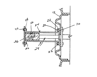
Referring now to Fig. 3, the wheel 12 includes a
plurality of threaded lugs 20 and lug nuts 22 for mounting a
tire thereon.
However, the size and position of the lugs 20 varies
considerably from vehicle to vehicle. Wheels of United States
and imported automobiles and light trucks have lugs on
diameters of 4 inches, 4-1/2 inches, 4-3/4 inches, 5 inches,
5-1/2 inches, and 6-1/2 inches. The number of lugs may be
four, five, six or eight. In addition, the size of the lugs
may be 7/16th inches, 1/2 inch, 9/16th inch, or 5/8th inch in
diameter. Furthermore, the threads on the lugs may be left or
right threads, have different thread counts as well as metric
versions thereof. Therefore, it is generally impractical to
provide an attachable winch threadably connected to each and
every type of possible lug configuration and pattern.
~28463~
Referring now to Figs. 1-3 the winch 10 generally
includes a plurality of attachable brackets 24 having an
elongate body 26, a first end 28 and a second end 30. The ends
28 and 30 are perpendicular to the body 26. The first ends 28
have a first opening 32 sized to fit over the lugs 20 and to be
secured to the wheel 12 by a lug nut 22 with the aid of the
vehicle lug wrench. The openings 32 are sized to fit over a
plurality of lug sizes. Preferably, the size of the opening 32
is ll/16ths of an inch and thus are of a size to fit over the
diameters of all standard size lugs. Since the first ends 28
are secured to the wheel 12 by the lug nut 22 the bracket 26
may be secured to all types of wheels irrespective of the types
of threads on the lug 20. This is highly advantageous over a
conventional threaded rod of prior art devices since the
threaded rods are expensive to manufacture and can only be
connected to a single size and thread type of lug. The present
bracket 24 fits all conventional wheels because the openings 32
placed over the wheel lugs 20 are large enough to accommodate
all conventional threads, whether left or right, whether metric
or not, and irrespective of size. Furthermore, the brackets 24
are inexpensive to manufacture as they can be easily stamped
without requiring machinery and the brackets 24 will fit all
conventional cars and light trucks.
The second ends 30 of the brackets 24 each include a
second opening 34. In the preferred embodiment, the openings
34 are of a size smaller than the openings 32 for reasons to be
more fully discussed hereinafter.
Another important advantage of the brackets 24 over a
conventional rod type winch is that sometimes, because of the
great amount of force exerted upon the winch 10, the winch 10
will bend. In the case of the brackets 24, the body 26 may
bend relative to the ends 28, but the lugs 20 will not be
damaged. On the other hand, with a rod support threaded onto
the lugs, the lugs 20 may become bent thereby damaging the
wheel 12.
Referring now to Figs. 1-3 and 7, an end plate 36 is
provided having a plurality of holes 38 (only three holes are
shown in Fig. 2 for purposes of illustration) positioned
radially and circumferentially for alignment with the second
openings 34 when the brackets 24 are secured to the lugs 20.
Preferably the holes 38 are positioned radially and
circumferentially for alignment with at least three lugs of
most vehicles even though they have lugs of differing radial
and circumferential positions. Bolts 40 and nuts 42 are
provided for extending through the second openings 34 and the
second end 30 of the brackets 24 to one of the holes 38 on the
end plate 36. In order for the end plate 36 to accommodate the
various circumferentially and radially spaced holes 38 to
accommodate most vehicles, the size of the openings 34, holes
38 and bolts 40 are less than the size of the openings 32 and
lugs 20. For example, a bolt 40 of 3/8th inch diameter with
accommodating openings 34 and holes 38 is sufficiently small so
to suitably space the holes 38 in the plate 36 without
weakening the plate 36.
Referring now to Fig. 5, an end plate 36a is shown
havin a plurality of holes thereon spaced circumferentially and
radially which will enable the plate to align with openings 34
in the brackets 24 for most conventional light trucks. Thus,
holes 50 are four in number spaced a radial distance of 3.250
inches from the center of the plate 36a and positioned
~X~6~
angularly at zero degrees, 90 degrees, 180 degrees and 270
degrees. Holes 50 provide places for securing four brackets 24
for use on a conventional truck having eight lugs 20 at a
radial distance of 3.250 inches. Holes 52 are radially
positioned a distance of 2.750 inches from the center of the
plate 36a at angular positions of 75 degrees, 135 degrees, 255
degrees and 315 degrees and thus provide support for four
brackets 24 for a six lug truck having the lugs at a radial
position the same as the holes 52. Holes 54 provide three
holes at a radial distance of 2.750 inches from the center of
the plate 36a at angular positions of 53 degrees, 197 degrees,
and 341 degrees for accommodating a truck having five lugs at
the same radial distance. Holes 56 are four holes at a radial
distance of 2.125 inches at an angular position of zero
degrees, 90 degrees, 180 degrees and 270 degrees for
accommodating a truck having four lugs at the same radial
distance. Thus, the plate 36a provides holes 50, 52, 54, and
56 positioned to accommodate most trucks.
Similarly, and referring to Fig. 6, plate 36b is
provided with holes positioned for accommodating most
automobiles. Thus, three holes 60 are positioned at a radial
distance of 2.750 inches from the center of plate 36b and at an
angular position of zero degrees, 144 degrees and 216 degrees
for accommodating a five lug automobile having the same radial
position. Three holes 62 at a radial distance of 2.500 inches
are provided at angular positions of 18 degrees, 162 degrees
and 234 degrees for accommodating a five lug automobile having
the same radial positions. Three holes 64 having a radial
distance of 2.375 inches are angularly positioned at 36
degrees, 180 degrees and 252 degrees for accommodating a five
~46$~
lug automobile having the same radially positioned lugs. Holes
66 are three holes at a radial distance of 2.250 inches from
the center of the plate 36b at angular positions of 54 degrees,
198 degrees, and 270 degrees for accommodating a five lug
automobile having the same radially positioned lugs. And holes
68 are three holes at a radial position of 2.000 inches and
angularly positioned at five degrees, 149 degrees, and 221
degrees for accommodating three lugs of a five lug automobile
having the same radial positioned lugs.
If the plates 36a and 36b are used as separate plates,
then the holes thereon may be enlarged as desired. However,
the preferred embodiment has all of the holes shown in Figs. 5
and 6 superimposed upon the plate 36 of Fig. 7 thereby limiting
the size of the holes 38 thereon. It is to be noted that in
superimposing the holes on the plates 36a and 36b upon the
plate 36, the holes on the plates 36a and 36b must be rotated
relative to each other to form a non-conflicting or
non-interfering hole 38 pattern.
Referring now to Figs 1-3, a circular support core 70
is provided for insertion coaxially between the inside of the
brackets 24 for supporting the brackets. While the core 70 may
not be needed in most cases, it is helpful when the vehicle 14
is deeply stuck and creates a heavy torque on the winch lO
which can in some cases, where the bolts 40 are of a small
size, cause shearing of the bolts 40. However, the insertion
of the core 70 acts to support the brackets 24 and the bolts
40.
It is to be noted that the components of the winch 10
can be assembled without the need of special tools as the lug
nuts 22 are tightened in place with the lug wrench of the truck
~Z84~
and conventional automobile tools may secure the bolts 40 and
nuts 42 in place.
In use, a lug nut 22 is removed from the wheel 12 and
the opening 32 of a bracket 24 is placed over a lug 20 and the
lug nut 22 is replaced to secure the first bracket 24 to the
wheel 12. This operation is repeated for the remainder of the
brackets 24, a core 70 may be inserted for additional strength,
and a plate 36, 36a or 36b is secured to the second ends 30 of
the brackets 24 by the bolts 40 and nuts 42.
The present invention, therefore, is well adapted to
carry out the objects and attain the ends and advantages
mentioned as well as others inherent therein. While a
presently preferred embodiment of the invention has been given
for the purpose of disclosure, numerous changes in the details
lS of construction and arrangement of parts will be readily
apparent to those skilled in the art and which are encompassed
within the spirit of the invention and the scope of the
appended claims.
What is claimed is: