Note: Descriptions are shown in the official language in which they were submitted.
:`
;: :
RADIOLUCENT HOSPITAL BE~ SURFACE
This invention relates to patient support~
; and more particularly to radiolucent patient 3upport
~ surfaces.
:,
The varied environments in whiah radlolucent
. patlent supports are required are attended by certaln
characteristics which make even pre~ent day ~upport~
in6ufficlent for universal use. Many such current
fiupport~ are highly specialized for particular applica-
', tions, such as the cantilevered, extendible support~
used in large, immobile tomography apparatus, or the
~:~ rigid ~upport tables provided on x-ray machines.
,:
~ While useful for their intended special function with
, ~ --
the noted equipment, these supports are not generally
8~ful in hospital patient support application~ where
,,.~
many other parameters mu~t be con,sidered.
For example, and particularly with respect
~ to p~tient supports or stretchers used in emergency,
!.'`~ ~ critical care, or out-patient areas, mobility of the
enti~e support structure and articulation of support
~: ~ sur~aces are important features. Stiffne~s of the
; ~ .
surface is also of prime importancel due to s~resses
~ 1 -
.
,
~`
.,,~` :
. ~ ,
, ' ' . ~ :
:................. . .
~10~'
placed on the surfaces during certain procedure~. The
vigorous chest compresslon forces generated in the
per~ormance of CPR, for example, tend to deflect the
pa~ient support. It must be of rigid construction in
,~ order to withstand repeated use without fatigue and
'~ failure.
; At the same tim~, it is desirable to use
~; x-ray, fluoro~copy, or "C"-arm mounted diagno~tic or
treatment equipment with a patient supported on a
i surface support o~ the type used in emergency, crltical
care, or out-patient areas, For this rea90n, the
Il,
support must comply with the one millimeter of Series
1100 aluminum equivalency att~nuation standard of the
~i Unlted States Food and Drug Administration (F.D.A.).
,:
This standard requires that any surface or ~tructure
lying in the wave path must produce no more attenu~-
tlon than a Series 1100 aluminum sheet one millimeter
:::
thick. This attenuation standard makes it difficult
~ to increase ~upport rigidity without additional
,..,~ .
~ structure which would urther attenuate wave energy~
-~ The stretcher manufac~urer i~ thus caught
~ betw~en the necessity o providing an articulated but
`~ rigid patient support structure capable of with-
standlng repeated stresses such as those produced in
CPR procedures on the one hand and the limitation of
the F.D.A.'s one millimeter alumlnu~ equivalency
standard on the other hand. When the support is
-2-
. ~ .
'' , '': . .
.
' ~ ,
~S~)3
-3-
strengthened by additional ~tructure or increa3ed
support thicknesses to increase rigidity, the equiva-
lency standard is breached, or the reinforcing struc-
ture within the x-ray area causes aberrations on the
, . .
x-ray film plate.
In an effort to provide a stress-resisting
patient support, and to meet the F.D.A. radiolucency
~t~ndard, hospital beds or stretchers have hLstori-
cally been constructed of aluminum or steel sheet,
with an aluminum patient support pan, fox example,
riveted to a support frame.
More recently, a variety of sheet pla~tics
have ~een utilized for the pans to allow for radio-
lucency of the surface. This increasing use of
plastics is driven by an increased frequency of use of
portable x-ray ~ C-arm apparatus in the patient and
emergency room areas. While plastics thicker than one
millimeter may meet the F.D.A. equivalency standard,
the~r xolatively poor structural characteristics
require wall thicknesses of 3/8" to 1/2" to provide
some degree o rigidity. Toleran~es ~ecome very
critical a~ t~e thicknes~es required for rlgidity
approach the one millimeter of aluminum equivalency
standard.
Such aluminum or plastic surfaces as are
.
currently in use do not generally perform well in
excessive loading situations, and may flex too much in
3-
! ~
1,
f~
'' ' ' : '
: . .
~, ' ' ' , '
' ' ' ' ' ' ' : '
': , : ' . ,
',~ , , ,' ' .,.:.
~128~ 3
-- 4 --
CPR activities, for example, where downward forces applied
to a patient's torso stress the bed surface. The patient
surface deflects and "oil cans", bows, or creases. Such
flexing can elongate the pan-to-~rame rivet holes. Even-
3 5 tually, a new replacement pan is required. Flexing at
notches on plastic material surfaces causes them to fatigue
and fail. Moreover, joints associated with the prior pans
and frames are difficult to clean of blood or other fluids.
It is thus desirable to provide an improved patient
lo support surface which is both sufficiently rigid and strong
enough to withstand repeated str~ess, such as pxoduced in CPR
procedures without undue ~atiyue and failure, and at the
same time is suff:iciently radiolucent in a predetermined
area ko meet or exceed the F.D.A. one millimeter of aluminum
equivalency attenuation standard and to provide a clear x-
ray plate without aberrations or artifacts due to support
surface structure.
Accordingly, it is a feature of one embodiment of this
invention to provide an improved radiolucent patient sup-
port.
A further feature of one embodiment of the present
invention provides an improved radiolucent articulated hos-
pital bed or stretcher surface.
A further feature of one embodiment of this invention
:::
has been to provide a reinforced radiolucent hospital bed or
stretcher surface providing reduced, uniform, electromag-
netic wave attenuation.
A further feature of another embodiment of the inven-
tion provides an improved radiolucent hospital bed or stret-
cher surface having uniform electromagnetic wave attenuation
and being capable of withstanding CPR stresses without unde-
sirable flex and surface fatigue.
~; A still further feature of an embodiment of the inven-
tion provides an improved rigid patient surface constructed
from thin plastic material and providing an x-ray window
:
. ~
' ~
~,
- .
: ' ,
~l3Sl~
. ~,,
- 5 -
within applicable F'.D.A. standards without producing aberr-
ations or diagnostically significant artifact. In another
aspect of the invention, there is provided an improved x-ray
plate cassette.
In accordance with an embocliment o~ the present inven-
,~ tion there is provided a patient surface comprising: a
patient supporting member having a predetermined radiolucent
area thereacross, and a non-planar radiolucent reinforcing
member having portions disposed in operative, normally
lo spaced-apart underlying relationship with the predetermined
ji~ radiolucent area; wherein the patienk supporting member and
the rein~orcing member are ~ormed as one integral unit: the
rein~orcing member portions providing de~lection resisting
; support for the patient supporting member when it is loaded.
In accordance with another embodiment of the present
, invention there is provided a patient sur~ace comprising: a
patient supporting member having a predetermined radiolucent
area therein, and a corrugated radiolucent reinforcing mem-
ber having a plurality of ribs transversely disposed in
operative, normally spaced apart and underlying relationship
with the patient supporting member across the predetermined
radiolucent area thereof when the patient supporting member
is unloaded.
In accordance with a further embodiment of the present
2s invention there is provided a patient supporting apparatus
comprising: a stretcher frame having ~longated side members
and transverse members lying the elongated side members; a
trunnion mounted on each of the si~e members defining a
pivot axis thereacross; a patient support frame pivoted to
the trunnion; a patient support element mounted on the
patient support frame and including: a patient supporting
member with a predetermined radiolucent area therein, and a
corrugated radiolucent reinforcing member having a plurality
of ribs disposed in operative, normally spaced apart and
underlying relationship with the patient supporting member
:
~.
.
351()3
- 5a -
across the predetermined radiolucent area thereof when the
patient supporti.ng member is unloaded.
In accordance with another embodiment of the present
invention there is provided a patient support element com-
s prising: a flat plastic sheet having a predetermined radio-
lucent area therein; a corrugated plastic sheet underlying
the flat plastic sheet, no section o~ the corrugated sheet
~ underlying the predetermined radiolucent area forming an
,~ angle greater than 45 with respect to the ~lat plaskic
: lo sheet; and a perimeter structure outside the predetermined
radiolucent area joining the peripheral edges of the sheets.
In accordance with a further embodiment of the present
invention there is provided a patient surface comprising: a
patient supporting member having a predetermined rad.iolucent
area therein; and a corrugated radiolucent reinforcing mem-
ber having a plurality of ribs transversely di.sposed in
operative, underlying relationship with the patient sup-
porting member across the predetermined radiolucent area
thereof, the radiolucent area of the patient supporting
member and the corrugated radiolucent reinforcing member
thereunder comprisiny, in combination, a relatively uniform
thickness for uniformly attenuating electromagnetic waves
- passing through both the radioluaent area, and the reinfor-
: cing member.
2s In accordance with another embodiment of the present
invention there is providPd a patient ~urface comprising: a
patient supporting member having a predstermined radiolucent
area thereacross; a non-planar radiolucent reinforcing mem-
ber having portions disposed in operative, normally spaced-
~ 30 apart underlying relationship with the predetermined radio-
; lucent area; the reinforcing member portions providing
deflection resisting support for the patient supporting
member when it is loaded; wherein the patient supporting
~;~ member in the radiolucent area and the reinforcing member
thereunder in operative combination uniformly attenuate
~: ' ' ~ '' ". '
, ' ' '
51C)3
~'
- 5b -
. electromagnetic waves passing therethrough; and wherein the
,~ reinEorcing member portions comprise a plural.ity of trans-
versely extending projections defining crests and depres-
. sions underlying the radiolucent area of the patient sup-
.. ~ 5 porting member.
~: To these ends, a preferred embodiment of the invention
is based on applicant' 5 discovery that a white or light-
colored plastic patient support sheet typically about .093"
in thickness for a preferred material, backed up by a
lo slightly spaced apart corrugated sheet of the same thickness
where the corrugated walls do not exceed an included angle
of about 45 with respect to the support sur~ace, will uni-
~ormly attenuate electromagnetia wave energy within the
F.D.A. equivalency standard, without producing aberration or
diagnostically signi~icant artifact, and at the same time
will provide sufficient resistance to
;
.~
"
` '
:~ 35
~'
, . '
~ 1~85~L0~
-6-
deflectlon so a~ to wlth~tand procedural fstr~99e~ ~uch
as those generated in the delivery of CPR. The
preferred embodiment comprises a hospital bed or
s~retcher surface having a flat sheet-like patient
:; .
~- support element, and an underlying ribbed, sheet-like
reinforcing element. ~oth sheets are made of synthetic
materials and their combined wall thickness, over a
predetermined area~ is substantially uniform. The
ribbed rein~orcing element ifs a corrugated sheet
:i~
~ having a plurality of transversely directed and
.,:
parallel ribs or corrugatlons. The crest~ of the ribs
are normally spaced from the patient support element,
but engage and support that element when that el2ment
is slightly deflected. The curving walls of the
corrugated reinforcing element are maintained at
angles of less than 45 with respect to the plane of
the patient support element such that the effective
,~:
, wall thickness of the two overlying elements through-
f~ ~ out a predetermined area of the surface is uniform,
and f3ub~tantially equal to the combined thickne~e~ of
~.
~ tho ~heet material in each element. Preferably, the
.
patient support and reinforcing elements are blow-
molded in an integral piece. Joints and overlaps of
material are eliminated. This makes the support more
rigid and easier to clean.
,"
~ By careful choice of the mqlecular weight of
;::
f ~ the polymer chosen and the type of manufacturing
f ~
, .:
~ -6- ~
, i
,: .:: .
.~`''
.,~
',~
' ~ ' '
.~ ~ . . . .
'~ ' . ' . .
,
, ~ , .
~: , ' ';
~ 5~3 _7~
/ process, it i~ pos~ibls for the crests of the rib~ to
be "kl~5ed off" or touch the patient support element,
~; In the preferred embodiment herein described, this
.,
contact is avoided. However, use of a lower molecular
'~','
~ weight material and a more dimensionally accurate
`' process, for example injection molding, could allow
:,
,~ this contact o~ the sections to take place. Such
contact may include an int:egral contact of rib crests
with the patient surface element wherein the material
' is fused together.
~,
There are no vertical walls in the sur~ace
within the predetermined x-ray window to cau~a non-
unlform wave attenuation. The F.D.A. one millimeter
of aluminum equivalency tandard is met, yet the
patient ~upport element is adequately supported by the
reinforcing element-against fatigulng flex. CPR
related and other stregses, can thus be applied to the
surface without undue deformationl while accurate
x-ray and other wave diagnostic or treatment processeR
can be provided without aberration due to the sur~ac~
:~ .
tructure and without exces~ive dosing.
An improved x-ray plate holding cassette i~
also provided with handles operatively coupled to cams
for adjustably securing the cassette underneath the
patient support by interacting with adjacent frames or
rails of the supportO
':.'
''''`~'' '
~ -7-
.; . .
,0., ~
.. ~ .
,
()3
These and other objects and ~dvantages wlll
, become even more readily apparent from t~e following
; description of a preferred em~odiment o~ the inven-
: tion, and from the drawings in which:
Fig. 1 is a perspective view illustrating a
- preferred embodiment o:E the invention as a hospital
,~; stretcher;
,: Fig. 2 is a plan view o~ the invention as in
Fig. 1, showing parts thereoE broken away ~or clarityt
:
, Fig. 3 is an elevational view o~ the patient
'~ . support elements oP Fig. 2~
Fig. 4 is a cross-~ectional view of a
portion of the head and torso element show~ ln Fig. 2;
Fig. 5 is a cross-sectional view ta~en along
lines 5-5 of Fig. 2;.
Fig, 6 is a perspective diagrammatic view of
~`:
certain features of the underside of the torso section
~; of the patient support ~urface of the invention;
~: Fig. 7 is a view similar to Fig. 4 but
having a oamed core as an altex~ative embodiment;
Fig. 8 i~ a diagrammatic plan view of the
x-ray caq~ette locking cams; and
Fig. 9 is a cross-sec~ional view similar to
Fig. 4 illustrating an alternative embodiment of the
~ invention.
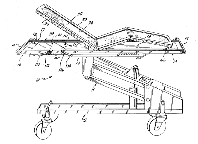
: Turning now to the drawings there is shown
in Fig. 1 a hospital stretcher 10 according to a
,
.,
-8-
..
,.
-
, ' , . .
',
.
~,2~5~(~3
,, g
-~ preferred embocliment of the invention. While the embodiment
of the invention shown in Fig. 1 has particular applicakion
and utility as a mobile hospital stretcher, it will be
appreciated that the invention has other applications such
as for hospital beds or other types of supports for pat
' ients. The apparatus 10 as shown in Fig. 1 is outfitted
with wheels so that it can be moved about from place to
place. It includes a cantilevering lift apparatus 11,
extending between the lower frame 12 and the upper suppor-
ting frame 13 and the apparatus it supports as will be
described. The lift apparatus is similar to that which is
disclosed in the commonly owned United States Patent Mo.
4,751,754, issued June 21, 1988.
It will be appreciated that the lift 11 and the lower
frame 13 do not constitute any part of the particular inven-
tion of this present application. Suffice it to say that
the lower frame 12 provides a stable mobile frame which can
;~ be moved about on the castors or wheels while the lift 11
~; provides a means for raising and lowering the suppoxt frame
13 as may be desired.
~ The support frame 13 includes end frame members 14 and
'"~ 15, and two elongated side frame members 16 and 17. Side
frame member 16 and 17 may also be joined together inter-
mediate their ends by
',
.
,~ ~
'
'
~ 2~35~03 - 1 o -
other frame members lnot shown). Al~ninutn pans 18 and
19 extend across the 3id~ rame members 16 and 17.
The frame 1~ is also provided with raisable
side rails 20 and 21 which are shown in a lowered
'~ position in Fig. 1. In their lowered position, the
side rails 20 and 21 lie in approximately the same
plane as do the respective elongated s,ide frame~ 16
and 17, and are spaced apart therefrom a pre~etsrmined
distance as perhaps best seen in Fig. 2 and 5. When
raised, the side rails inhibit a patlent'5 inadvertent
falling from the stretcher.
A patient support surface 25 is carried by
support frame 13 and includes a head and ~or~o s~pport
.~ element 26, a hip and thigh support element 27, and a
lower leg and foot support element 28. The elements
~ 26, 27, and 2B are articulated about pivot axe~ 29 and
,~ 30 (Fig. 2) so that they can be positioned in a flat
horizontal plane as indicated in Fi~. 2 or in any
articulated condition as shown in Fig. 1.
The pivot ax~s 29 is defined in part by
trunnions 31 and 32 mounted on frame 13 and to which
respective end~l of the elements 26 and 27 are pivo~ed.
Each of the elements 26 and 27 are provided with
~; ~orque arms 33 and 34, respectively. Torque axm 33 is
attached to a rectangularl~-shaped frame 35 by means
of brackets, such as the bracket 36 and frame element
37 as sho~n ~ Fig. 2. ~hile br~cke~ 36 and frame
-10-
: ;
:: . . :
: . ,
..
, . . .
~285~l03
element 37 are o~ly shown in the lower portion of Fig.
2, it will be appreciated that the upper portion has
similar construction, which is simply not seen since
it is beneath the patient support sur~ace 25 in the
upper part of Fig. 2~ The rectangularly-shaped frame
35 includes side rails, such as at 3~, and another
parallel side rail on t'he opposite side of the element
26 (llOt shown in Fig. 2), as well as an end rail 39,
A bracket 40 is attached to the torque arm
33 and has one end attached to a pneumatic spring 41
which has an extensible rod 42 connected through a
bracket 43 to a frame member 44. Any ~uitable and
well-known pneumatic spring can be u~ed. The apring
41 has an actuating button 45 located in the end of
extensible rod 42. A lever 46 is secured to pivot
bracket 47 which is mounted on ~he bracket 43, and is
connected to actuating cables 48, which extend
respectively to control handles 49 and 50 located at
- the left end of the apparatus as shown in Fig. 2.
When at l~ast one of the handles 49, 50 are squeezed
outwardly, the cables 48 are tensioned, pulling the
lever 46 toward the le~t hand or head end o~ the
~ ap~aratus. In view of the fact that the lever 46 is
`~ pivoted at 51 to the bracket 47, the lever engages
actuating bu~on 45, releasina the pneumatic spring
and permitting the pis~on 42 to extend. Extension of
the piston 42 rotates the bracket 40 and the torque
, ~
:, :
.' ~ ,.
.
,~ .: . . . . .
. ' ' ' :
.
'
~ 3 -12-
arm 33 in a clockwi3e direction with rcspec~ to the
pivot axis 29, thereby ral5ing the element 26 to a
desired inclination. It ~Jill be appreciated that the
cables 48 run through interior frame members, such as
fra~e ~ember 52, for example, secured to the outer
side frame members 38 by means of bracket members 37
and 53, and providing further stiffening.
In a similar fashion, the torque arm 34 of
element 27 is connected to the element 27 via brackets
55~ frame members 56~ inner frame members S7, and
outer frame members 5~. ~dditional ~rame elements 59
secure opposite ends of the inner and outer ~rame~ 57
and 58 together. Torque arm 34 is secured to one end
of a bracket 60. The other end of the bracket 60 i~
connected to a pneumatic spring 61, actuated in
similar fashion as that of spring 41 by mean~ of
.;
cables 62, extending to control handles 63 and 64 at
the right hand or foot end of the apparatus as ~iewed
in Fig. 2. Operation of at least .one of the control
handle~ 63, 64 permits actuation of the pneumatic
spring 61, causing torqu~ arm 34 to rotate in a
`~ counter clockwise direction about pivo~ axi~ 29 and
thereby raising the element 27 in a counter clockwise
: fashion to a position, for example, such as that shown
in Fig, 1.
pon this actuation, element 28 is carried
by pivot elements 65 (Fig. 2) and a similar element
:: ~
:~ -12-
, :
'
: ............................. .
.. . , .. : .
.
, ~ .
. .
' '~ ':, ''~ ' ' ' ' ' ' '
. ~ , .
~1 2~51~)3
-13-
not ~hown on the opposite side t.hereo~, such that it~
end which ls attached to element 27 i~ also raised,
Each side of the opposite *nd of element 28 i5 provided
with a pair of support links 66. Each link 66 has a
lower end 67 operatively engagir.g a rack 68 on frame
13. As the element 28 is raised due to motion of the
movable pivo~ axis 30, t:he end of the element 28
opposite the pivot axis 30 can also be raised and
maintained in a desired position by mean~ of the
support links 66 and their interaction with the rack
6~.
The head and torso support 26 of the patient
support surface 25 is provided at its head end with
legs ~9 for supportin~ the patient support surface 25
slightly above the side rail 16 and 17 of the frame
13. A pair of legs 70, only one of which is shown in
Fig. 3, is disposed on the patien~ support surface 25
beneath the axis 30 to support the elements 27 and 28
above the side rails 16~ 17. Legs 71 are secured to
the foot end of the element 28 and shown in Fig. 3 for
supporting that end of the element above the side
frames 16, 17, one leg 69, 70, 71 being located on
each side of the patient support surface 25. Accord- -
ingly, it will be appreciated that the multiple
element patient support surface 25 is articulated and
is mounted on the frame 13 for posltioning as
desc~ibed, Thus the pa~ient's head and tor50 can be
. .
..
' ' :
' '
.
~ ~5103
: rai~ed or a patient 15 thigh and lower leg area can ~e
raised, and articulated at the patient's kneeq in
order to provide an appropriate patient po~ition.
Turning now to the patient support surface
~ 25, it will be appreciated that that surface is
:~ preferably comprised of three elements 26, 27, 28 a~
noted above. It will also be appreciated, however,
.. that the support surface could be an integral 5upport
sur~ace, not articulated, and lying in a common plane
or in a plurality of planes a5 may be de~lred if
:!:
movable articulation we:re not necessary. A1YO~ it
should be appreciated that the patient ~upport surface
25 could comprise two, three, ~our or more elements
articulated to~ether as might be desired ~or any
particular application.
The patient support surface 25, according to
a preferred embodiment of the invention, provides a
sufficiently rigid patient support surface so as to
with~tand the stress and strain of certain procedures;
such as CPR, while at the same time providing a
~:
~ predetermined x-ray window which meets the one milli-
,,
. meter of aluminum equivalency ~tandard o~ ~he F.D.A.
¢~: and does not produce aberrations in the standard x-ray
film which is normally utilized, Accordingly, it is
; contemplated that an x-ray plate can be placed beneath
the patient support surface 25 for the purpose of
receiving x-radiation directed through a patient
-14-
1. :
:~ :
, ~ .
:: :
, ; ,
.~ .; .:,. ~ .
, : .
: ` ' ' " ' , '
,, . , :
~ 5~03
- 15 -
supported on the sur~ace 25 well within the F.D.A. stan-
dards.
In the drawings, it will be apprPciated that the
depiction of the patient support surface 25 in Fig. 1 is
, 5 diagrammatic. Details o~ the patient support surface are
:; more clearly shown in Fig. 2, wherein torso section 26 is
:,~ provided with side hand holes 80, corner hand holes 81, and
~ an end hand hole ~2. The hi.p and thigh section 27 i8 pro-
:~ vided with side hand holes 83. The foot section 28 is
. 10 provided with side hand holes 84, coxner hand holes 85 and
end hand holes ~6. The side and corner hand hole~ on the
~, opposite side of the patient: support sur~ace 25 are not
j shown in Fig. 2 ~or clarity as those sections are broken
. away.
~ 15 The structural details o~ the patient support sur~ace
j~ are perhaps best seen in Fiys. 4, 5 and 6. Fiys. 4 and 5
depict particular sections of a typical patient support
sur~ace as represented by the head and torso section 26 of
~: Fig. 2. It will be appreciated that the cross-sections of
the elements 27 and 28 o~ the patient support surface 25 are
similar. Each of the elements 26,27 and 28 are pre~erably
~ constructed integxally by a blow molding process, such that
.~ each of the elements compri.ses a sheet-like patient suppor-!~ ting element 90, and an underlying spaced apart, corrugated
sheet-like reinforcing
.~J'
'i~
,~
., .
~"`
,'~ :
~. '
.1`;
~'
~'
.'~ .
`:
3 ~16-
element 91. While blow moldincJ i5 preferred, other
processe~ such as injection molding or rotational
molding could be used. As perhaps best seen in Fig.
5, the patient support element 90 is slightl~ spaced
from the corrugated sheet~ e reinforcinq element 91.
Each of the elements 26, 27 and 28 has an
integral blow-molded side structure (be5t seen in Fig,
5), which comprises an integral reinforced side ~rame
92. Integral side framle 92 includes a raised 9ection
93 tapèring down at 94 into the integral patient
~upport element 90. The sidewalls of the element 26,
as shown at 9S and 96 depend perpendicularly from ths
ralsed element 93 and are laterally spaced from an
internal reinforcing rib defined by walls 97 and 98.
It will be appreciated that the space between the
facing walls 96 and 97 accommodate the interior and
exterior frame members such as 52 and 38, respectively
(Flg. 2) which themselv~s are preferably 1" by ~"
,:
~ formed metallic tubing.
.~ Accordingly , and from Fig . 5, it will be
apprec~ated that the entire patient support ~urface 25
~ integral, with the upper element 90 spaced from the
: lower element 91 such that ~he entire element, such a~
element 26 for example, can be blow molded. During
~; the blow moldi~g process, particular cores and the
`; like are utili~ed in order to provlde for the side,
~ corner and e~.d hand holes such as those illustrated at
:~ -16-
~ ' .
";
,.~.
:. ;
' ' , ' ':
' ' - ' :: ' '
~ 51~ -17-
80, 81 and ~2 in Fig. 2, lt being understood and
appreciated that the various bends in not only the
hand holes but in the edge walls 95, 96 and the
reinforcing rib walls 97, 98 add to the rigidity of
the entire patient support surface 25. A~ain, it will
be understood that while the cross section of Figs. 4
and 5 are taken through the element 26, the element 27
and 28 preferably have similar cross sections.
Turning now momentarily to Fig. 4, it will
be appreciated that the corrugated reinforcing element
91 has a series of elongated parallel ribs, includlng
parallel crests or projections 99 and valleys or
depressions 100 extending transversely acroqs portion~
o~ the patient support surface 25 and the re~pective
elements 26, 27 and 28. The crests 99 are slightly
spaced from the patient supporting element 90, while
the valleys 100 are further spaced from the patient
support element 90. At the ends of the elements
adjacent the pivots axis 29 and 30 for example, the
patient supporting element 90 is curved to meet the
reinforcing element 91 as at end 101 as shown in Fig.
As sho~n in Flg. 5, each of the corrugations
or ribs such as the rib 10', for example, terminates
in a vertical ~all 103, which is aenerally perpendicular
to the patlent supporting element 90. The ver~ical
wall 103 provides siynificant support in a perpendicular
17-
, . - .
~ .
.
.
.
.
~ 2~5103 -18-
direction with re~pect to the patient support element
90, and par~icularly upon any contact therewith.
It will be appreciated, particularly from
Fig. 4, tha~ the ribs, comprised of the alternating
crests 99 and valle~s 100 of the reinforcing element
91, are of uniform wall thickness. The walls of the
ribs are disposed at an angle of no more than approxi-
mately 45 with respect to the patient supporting
element 90. Accordingly, it will be apprec~ated that
the combined thicknesses o~ the element 90 and 91 at
any place thro~qh their cross ~ection between the end
walls 103, are substantially uni~orm, and will not
produce undcsirable aberrations or diagno~tlcally
,
significant artifacts on a standard x-ray plate.
For description purposes, Fig. 6 illustrates
a predetermined area or radiolucent x-ray window "w"
which is considered ~o be an x-ray window in the
surface 25, This window lles over the surface 25
interiorly of end walls 103, the head and foot end~ of
the ribbed reinfor~ing element 91, and all frame
structure.
~.
While it i9 recognized that there i5 a very
slight variation in the effective thickness of the
.~ element 91, depending on the precise location at which
such thicknes~ would be measured within the window
"w", the thickness variation, caused by the angulation
of the element 91 with respect to the element 90, is
: :
-18-
~,
, ~ .
;~ ~
'
, . ~ .
, . :
. . , . . :
~ 285103 -19-
not sufficiently great enough to generate any a~erra-
tion in an x-ray plate of the type normally Utilized
in a diagnostic x-ray procedure. It has been deter-
mined that if the an~ulation of the element 91 with
respect to the patient support element 90 i5 main-
tained within this 45 range, vertical support walls
beneath the patient and in the predetermined x-ray
willdow are eliminated. Accordingly, there i8 no
support or xeinforclng structure in the predetermined
area "w". Aberrations or artifacts normally cauqed by
such vertical walls in the area "w" are not produced
on the standard x-ray plate placed beneath area "wn.
Thus electromagnetic waves directed through the
predetermined area "w" are uniformly attenuated
without aberrations so that an accurate x-ray picture
can be formed.
Turning now to Figs. 4 and 5, it will be
appreciated that the patien~ support surface 25, a~d
particularly its elements 26, 27 and 28, are. pre~erably
made of a synthetic material such as the plastic
material known a f NORYL 190, manufactured by The
General Electric Company prior to this invention, u~e
of this or of similar materials, in the thin sheets
contemplated herein, was not suitable due to lack of
rigidity which is required in the suppo~t. While
NORYL 190 is a ~referred material, other polymers and
copclymers could be used. Preferably the wall
, ;,:
", -19-
~ .
~ ' .
: ~ ~l2~5~
- 20 -
thicknesses of elements 90 and 91 of the patient support
surface 25 as illustrated by the arrows A and B o~ Fig. 4
are each preEerably less than about .100" and particularly
are preferably about .093", making the combined wall thick-
s ness approximately 0.186" throughout the predekermined area
"w" as shown in Fig. 6. These wall surfaces are normally
spaced apart at the peak 99 of the corrugated reinforcing
element 91 a distance such that the overall thlckness,
including the distance "C" between the uppermost surface of
the patient support element 90 to the lower surface o~ the
reinforcing element 91 is approximately 0.250~'. Accor~
dinyly, the normal spacing between the reinforcing element
91 and the patient support element 90 at the crests 99 i8
approximately 0.064". In the preferred embodiment, the
;~ crests 99 are parallel and spaced apart about 4 1/2ll and the
distance l'DII is about 1". The entire support sur~ace is
about 26" wide. Element 26 is about 32 1/2" long, element
27 about 24 1/2" long and element 28 about 24 1/2" long.
The predetermined area "w" is ahout 18" wide between rib end
walls 103 and about 26" long in a head-to-foot direction in
element 26. The size of area "w" may be varied in the dif-
,~ fering elements 26,27 and 28 to accommodate a desired aber-
ration-free x-ray window within the F.D.A. minimum equi-
valency standard.
.
~:
.
~,2~ 03
- 2 1--
When a patlent is placed on the patient
sUpport sur~ace 25 and on its various elements, i~
will be appreciated that the p~tient support element
90 may slightly deflect, coming into contact with the
crest portions 99 of the underlying reinforcing
element 91. Vpon contact with the reinforcing element,
further deflection of the p~tient supporting element
90 is slgnificantly resisted such that the overall
patient support sur~ace 25 ~provides a rigid support
for the patie~t. The surface 25 is khus capable o~
withstanding procedural stresse~, such as any CPR
stresses applied to the surface through the patient.
The vertical wall sections 103 are close enough to aid
in providing perpendicular resistance to de~Lections
required, without impinging in the predetermined area
"w". Al~so, the integrated structure of the support
element, whether it is element 26, 27 or 28, serve to
further rlgidify each of the respective elements and
resist deflection.
I~ should be kept in mind that while this
preferred embodiment spaces the patient support
element 90 from the crest portions 99, it is possible
to select a molecular weight of polymer or copolymer
.,: ,
and a process that would allow these portions to
contact one another.
Fig. 9 shows one such type of contact
wherein the reinCorcing element 91a is integral with
i;:
,:~
-21-
.
~ - .
:
,~
,
1~5~(33 ~22-
patient support element 90a at crest 99a in an ~lterna-
tive patlent head and torso support element 26a, The
thickness of the in~egral crest area 90a i5 preferably
about the same as that of the patient support element
90a and reinforcing element 91a where not joined, in
order to reduce or eliminate diagnostically significant
artifacts.
In addition, it will be appreciated that an
alternative embodlment o~ the patient support suriace
25 might include slmilarly constructed element~ but
one or more having a foam material F deployed in the
internal section of the patient support between the
patient supporting element 90 and the rein~orcing
element 91. This could ~urther rigidlfy and ~trengthen
each particular patient supporting surface. Thi3 ls
shown diagra~natically in Fig. 7, which is similar ~o
Fig. 4 with the exception of the illustra~ion of the
foamed core F. Like numbers in Fig. 7 designate
elements like those of the preferred embodiment. In
such a construction, the wall thicknesses of the
elements 90 and 91, togethex with the foam material F
are ~elected in order to meet the F.D.A. attenuation
standards and yet at the same time provide a rigid
patient support. While this foam-filled structure can
meet the~attenuation standards, it does create some-
what more o~ artifact problem than does the previ-
ously described preferred embodlment.
22-
. .
..
23-
In another aspect of this invention, (Pigs.
1, 2 and 8) the stretcher 10 is provided with an x-ray
cassette 110, comprising a tray 111, a bracket 112,
and actuatiny handles 113, 114. The tray is particu-
larly configured for holding a standard x-ray plate
(not shown). Each of the handles 113, 114 are secured
via pins 115, 116 through bracket 112 to respective
underlying cams 117, 118. The cams axe respectively
configured so that when the handle 113 i5 turned in a
counter clockwise direction, and handle 114 in a
clockwise direction, the cams present an enlarging
ramp between the side rail 16 of the stretcher 10 and
the lowered raisable side rail 20 as shown in Fig. 2,
A diagrammatic picture of this is shown in Fig. 8.
Accordingly, the cams are wed~ed between the frame
rail 16 and the side rail 20 to retain the cassette
110 in its proper position. When ~he handles are
rotated in the opposite directions respectively, the
cassette can be loosened for adjustment forwards or
backwards to properly mount an x-ray plate beneath the
predetermined area or x-ray window "w". Of course,
such a ca3sette is located above the aluminum pan 18
or above the aluminum pan 19 when performin~ x-ray
procedures in the thigh or leg area. As noted above,
each of the elements 27 and 28 include a predetermined
area or x-ra~ window "w" which provides rigid patient
-23-
~ L~8~;~03
support and uniform attenuation within the F.D,A,
standard and 9imilar to area "w" of element 26,
It will thus be appreciated that the in~en-
tion provides a patient support surface having pre-
determined areas which provide uniform radiolucency
therethrough such that there are no aberrations or
diagnostically significant artifacts depicted on the
normal-type x-ray plate and F.D.A. attenuation
standards are met. Also, despite its preferably thin
wall thicknesses, the pat:ient support sur~ace i~
sufficiently rlgid so as to be capable o~ with~tanding
stresses and strains such as those normally applied to
a patient support surface such as by CPR procedure,
for example. ~he rigid structure in the preferred
embodiment of the invention substantially re~ists
deflection of the type o the which will tend to flex
the patient support surface and cause it to fatigue or
crack during normal usage. In addition, the integrated
; blow molded patient support surface elements provide
unitary surfaces without cracks, depressions and
joints which are difficult to clean.
It will also be appreciated that whil~ the
described corrugation configuration of the reinforcing
element is preferred, other non-planar reinforcing
element configurations might also be used to produce
rigidifying results, maintain the F.D.A. attenuation
standards, an~ provide aberration-free x-rays.
-~4-
,
.,' ' ~ .
.
.
~351()3
- 25 -
Moreover, it should also be appreciated that the inven-
tion renders possible the usa of thin plastic materials
which are highly radiolucent and which otherwise could not
be used as a result of the interplay between the F.D.A.
attenuation standard and the need for stress resistiny
rigidity. Thus the selection of thin plastic materials
which could not ordinarily be expected to be used for a
radiolucent patien-t surface is made possible as a result of
lo the invention.
These and other advantages and modification6 will
become readily apparent to those of ordinary skill in the
art without departing from the scope of this invention, and
the applicant intends to be bound only by the claims appen~
ded hereto.