Note: Descriptions are shown in the official language in which they were submitted.
~ s~
MET~IOD ~ND ,~PP~TUS FOR CONSTRUCTION OF ARTIFICIAL RO~
' :,
i~ .
Baokground of the Invention
This lnvention relates to a new and improved method and
apparatus for the construction o~ artificiQl roads. In the
; drilling of oil wells or in the search for hydrocarbons or in
~;construction or repairing of di~ferent type devices in remote
~,';areas it is very difficult to enable truaks and other heavy
e~uipment to transport the necessary appsrstus and equipment to
ithe desired site because o~ poor ground conditions, for example,
if the ground is too wet such trucks and the 11~e csnnot traverse
a wet ground because they will become stuck. To overcome this
~;problem a complete service industry has grown up w}-ich is either
~.:
~a complete temporary road construction craw whi~h will 1~ down
: . , .
~;gravel, shale, or the like or board construotion crews which will
lay down as roads, a whole series of boards. Normally, to
:construot such a road the bosrds sre anywhere from ~0 ft. to 20
ft. long and anywhere from 1~ to Z~ inches thiok snd from 6 to 8
,. . . .
~'; inches wide and thus not only are very hsavy but al80 req~ire
manual manipulation in the ~orm o~ labor to aonstruct such board,s
ilate,rally to a width of 8 ~t. to 14 ft. ~nd longltudinally
sometimes for miles.
Further, while suah boards, when laid down, will support
~;heavy trucks, trac~ors, trailers and other equipment, becau~e of
~... . .
the expense involved yet another labor ln-tensive crew must move
back ln and, 1~ possible, separate such boards or pu11 such
boards apart. Pulling suoh boards apart i~ o~ten diffioult
beGause suoh boards are normally nailed with big heavy penny
,. . . .
nails hammered into the board~ with axes or sledge hammers.
' `Thus, such board road construotion Is not only very labor
intensive but is also very dangerous because o~ the weight and
build of the boards and it i8 also very oapital intensive beoause
~of the number of board feet involved. Further, it ls often
;diffioult to remove suoh board,, if at all, more than one tlme
',' 1
5~
~nd beoause such boards mus~ be singularly torn apar~ and grouped
together the usable llfe of ~uah boards i8 not great when
oompared to the use/008t lnvolv~d t ' ' . . . ' . ',
Summar~ of the Invention
~ ho purpos~ of th~ ~r~sent lnven~lon ls to att~mpt to
provida Q romQdy for tlle construation o~ ~uoh bo~rd rond~ by
providing a prefabricated matt ~y~tem wherein the board road~ not
only do not have to be nailed together in the field but are also
interlocked such they will not be nailed toge~her and further
such board matts can be laid down in interloak~ng relationship in
a much guicker and more economioal period o~ time thus saving
labor costs in the laying and dlsmantllng o~ ~uoh board roads.
In addition such board roads may al~o be oxpa~ded or
contracted such that the road may be expanded laterall~ with
respect to the width o~ the arti~ioial road and it ~s to be
understood that such interlocking relation~hip relativs to the
matrix system 18 such that the matrices'and mattlng sy~tem may be
expanded radially relativa to a center area ~or turnarounds or
other working'operations that i~ dasirad.
According to a broad aspect the invention relates
to an interlocking mat system for the construction of
temporary roadways, working areas and the like,
comprising: I
(a) an upper mat having a substantially planar upper
face and, having a plurality of spaced ridges
including end ridges and interior ridges forming a
lower face and defining spaced channels
therebetween, two of said ridges being flush with
respective ends of said upper mat, at least one of
said interior ridges being of greater width than
said end ridges; and,
(b) a lower mat having a substantially planar lower
face and having a plurality of spaced ridges
forning the upper face thereof, said spaced ridges
,~,
35166
and channels of said lower face of said upper mat
establishing complete interlocking relation with
the spaced ridges and channels of said upper face
of said lower mat when said upper and lower mats
are placed in superposed assembly.
According to a further aspect the invention relates
to a temporary decking system to facilitate
t.r~n.q~ort~tion over ~oor 80.~1 and ro~ h t~rraln
condLtions comprlslng a plurallty o~ like, overlapplng
units placed in at least first and second horiæontal
layers vertically disposed relative to each other, each
unit comprising i.nner and outer faces wherein:
(a) said outer faces comprise a first group of
elements substan-tially longitudinally parallel;
(b) said inner faces comprise a second group of
substantially parallel runner elements attached to
said first group in spaced relation to one another
and transverse to said first group, wherein said
spaced relationship is such that said first and,
second transverse elements are disposed one near
each end of each unit and the remaining transverse
elements are positioned between said end
transverse elements to present at least one
interior ridge and so as to define at least two
channels between said end transverse elements
wherein each channel and each interior ridge is
approximately twice the width of sald end
transverse elements so that transverse ridge
elements of any one unit will conform to channels
of any other inverted unit, and when units are so
intercollnected durin~ instal.1ati.on will
~llbstantially prevent longitudinal movement of any
unit relative to adjacent units; and,
5~1L66
(c) wherein said first layer comprises a plurality of
units arranged in end to end relationship with the
outer faces down and wherein said second layer
comprises a layer of units arranged in end to end
relationship with outer fac,es up and arranged so
that each unit in said upper layer overlaps at
least one adjacent unit in the lower level, and so
th~t each unit ln the upper layer interlocks ~lith
at least two units ln the lower layer by flttlng
said transverse runner elements of one unit into
the transverse channels defined by the transver.se
runner elements of any other inverted opposed
unit.
According to a further aspect the invention relates
to a temporary road for placing through on and in rough
terrain for equipment and vehicles, said temporary road
compris.ing:
(a) a plurality of like sets each comprising first and
second matrices;
(b) each of said sets bei.ncJ cons-tructecl such that said
first matrices is the upper surface of said set
comprising loncJitudinclI elements and said second
matrices is the lower surface of saic] set
comprising spaced elements traverse to the
longitudinal elements;
(c) each of said sets of matrices being constructed
and laid down on such terrain such that up to as
: much as the first half of the second matrix of
said first set interlocks with up to as much as
the first half of the second matrix of the second
-2(b)
~ 2~35~L66
set and such th~t -the first half or more of the
second matrix of the third set interlocks wlth the
~3econ~ h~.Lf or IllOLe 0~ the second matri~ of the
sscond set;
(d) said matrices sets being asse~bled such that said
first set is longitudinally aligned with said
third set and said third set is longitudinally
aligned with the fifth set and such that said
second set interlocks said first and third set~
longitudinally only by ha~ing the second matrices
of the first and third set face the second
matrices of the second set et sequence;
(e) a perdurable topping applied to the upper surface
of the roadway; and,
(f) wherein assembly of said sets as set forth
hereinabove, constructs a temporary road which is
easily positioned and which also may be easily
removed and stored for reuse as desired.
According to a further aspect the invention relates
to an apparatus for maximizing weight distribution upon a
bearing surface comprising:
(a) a set of bearing plates; and,
(b) means for interlocking said bearing plates into
two layers whereln bearing pla~es in a first upper
layer will overlie and lnterlockingly connect with
up to four bearing plates ln a lower layer so that
-2tc)
~l35~
a load applied to the upper surface of any of said
plates in said first layer will be distributed to
said bearing surface through up to four bearing
plates within said second lower layer.
According to still a further aspect the invention
relates to a method of weight distribution to maximize
- weight distribution upon a bearing surface said method
: comprising the steps of: .----- ---- --
(a) manufacturing a set of substantially similar
bearing plates;
(b) providing means for interlocking connection of
; each of said bearing plates to one another,
(c) setting out a first lower layer of said bearing~
plates:
(d) interlocking a second upper layer of said bearing
plates with and over said first layer so that
loads bearing upon any one of said upper bearing
plates will be distributed over said bearing
surface by up to as many as four of said lower
be~ring plates.
; ,
Drio~ Do8arip~10n of tlle Drawlngs: ~ :
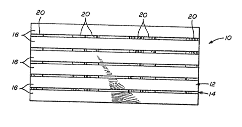
Flg. 1 is a top plsn view of one ~eotion of the artifloial
road of the present inventlon/
Fig. 2 is a bottom plan vlew of the arti~lalal road of the
.
present invention,
Fig. 3 is a plan view of a serie~ of interlooked sections of
thi~ artificial road of the present inventlons
Fig. 4 is a side elevatlon of a s^ries o~ lnterlooked
sections of the artificial road of the pre~en~ inventLon.
'
n ~-
~2~3S~L6Çi
Descrlption of the Preferred Embocliment.
~ ig~ ot forth in do~ull tl~o pr~rred onabllllg
embodlnlont o~ ~ho pre3en~ lnventlon whlch lnolude~ ~nd oomprlse~,
as set forth in Fig. 1, a 8et of 10 board~ whioh oomprlse an
upper matrloes generally deslgnatsd at 12 and ~ lower matrices
generall~ deslgnated at 14. The upper m~trlae~ 12 generally
-2 ~ e )
~J ~J..285~66 ~
comprises a plurali-ty of boards 16 spaced and of ~uffioient
weight, width and length to support heavy eguipment and vehicles
because, as se-t forth hereinabove, such road i9 positloned and
laid down over impassable terrain by suGh heavy equipment and
~ehicles. As further set forth :In Figs. 1 and 2, th0 second or
lower matrices 14 is comprised of a plursllty of cross-support
members 20 for suppor-ting each of the longitudinal members 16.
As set forth in Fig. 2 each of the cro~ ~upport member~ 20
include at least one or more cro~s piece~ and, a8 further
lllustrated, may have more than one cro~s piece. As further
illustrated, each of the cross support member~ o~ the ~econd
matrices are spaced relative to eaoh other in a manner and ~or a
reason to be set forth in more detall herelnbelow.
:, ,
AS further illustrated in Figs. 3 and 4, the method o
constructing the temporary road i8 set forth and generally
illustrated by having a first set 22 longltudinally abutting a
~, .
second set 24 and interlocked by a third set 26. As ~llustrated,
...... .
; the first set 22 comprises a plurality o~ longitudinaliy spaoed
board members 28 comprising the upper fir~t matrix and a lower
: .
surface or second matrix comprising ~paced cross pleces 30, 32
and 34. Similarly the second set 24 comprises the first or upper
matrices comprising cross pieces 38 for the fir~t or upper
matrices and suitable spaced cross pieces 40, 42 and 44, It is
to be understood that the sacond matrise~ of each of the first
and second sets 22 and 24 comprises urther and additlonal oross
pieces which interlock with other sets to form the road.
:,:
The temporary road further aomprises the third set 26 which
compri~es a first matrices 48 of spaced longitudinally po~itioned
oro~ pleces and a second matrices whloh comprises aross pieces
l for supportin~ the first matrices whioh sre spaced relative to
,~ each other such as illustrated at 50, 52, 54 snd 56. As
illu~tra-ted in Figs. 3 and 4 and in operatlon the ~econd set is
positioned su~h that the first matrloes cross pieoes 26 are lald
on the ground G with the second matrlces positloned upwardly with
the second matrices cros~ pieoes 50 et. ~equenoe belng supported
.
.: . .. .
.:,
.-
i -3-
5~6~
and positioned transverse to the ~lrst matrices. Thereafter, the
~irst and third sets are laid such that the cro~s piece, 30 and
-the cro~s plece 40 of sets 22 ,end 24 6,re posltloned ~dJac~nt each
other and ad;acent the cross pleces 20 (Fig. 4) of the second
matrices of the second set so that such piecas interlock wlth
each other such that any pulling or tuggin~ of th0 bo~,rd roaa ln
the longltudinal direction of the flrst matrice~ of each of ,~uch
sets will be prevented so that the board road wlll not separate.
In this manner, such temporary board road has a trlple stac~ or
set o~ boards with the second matrioes o~ ~ach of said ~ets being
interlocked relative to each other and wlth the flr~t matrices of
each of sald sets either being on the upper or lower Eurface and
.: .
being posltioned parallel to each other for laylng out of the
board road and longi-tudinal directions as de,~ired. It should
: ~ ,
! especially be noted that by providing such interlocking txiple
stacks both the upper and lower surfaoes are comprised o~
unlnterrupted runs o* longltudinal board,~, each section in the
;~ series abuts the adjacent section( 8 j with no intermediate gap,~.
., .
;~ This provides a more even transfer of the load from equipment
using the road to the surface of the 80ii. A more even weight
distribution over the soil results, *his i8 especially dèslr,ed in
the areas with poor ground condition,s where temporary road
structures are needed.
;' Although not illustrated in the primary ambodim,ent depicted
in Figs. 1-4, under some conditions it might be desirable to
;1,, .
provids sacondary devices for interconnecting the mats.
. . .
Therefore, although the primary interloaking would be provided by
,~ the previously described positloning of oro3,~ pieae,~ 40 of set~
22 and 24 ad~acent each other and ad~ ao~nt the aross-pieces 20
(Fig. 4) of the second set, an auxlllary interlocking positioning
a guide can be provided by e~uipplng each set 10 with ~osts and
. .
CUp8 which correspond and connect with cup~ and po~t~ o~ any
other set when sets are correctly positioned and ~sssmbled into
the road as previously described. Many diff0rent aonfigurations
could be devisedO One example would plaoo posts along the
. :
;;; -4-
:.
.'', ~ ..
'.
midline underside of the two outer aross-suppo~t members Z0
deplated in Fig. 2, that is the extreme left and right membrane
corresponding cups would be positioned withln the underslde of
the upper boards 16 of Fig. 2. The cup~ would be placed to allgn
wi-th posts of a simllarly equipped set, thBt i8 at proper
locations Just off of the mldllne of the set, parallel to the
cross-support members 20. Each set would be ldentlaally equi~ped
with such CUpB and posts and therefore each set aould inter-
changedly be positioned to interlock with the oups a~d posts of
two other sets. Al-though only one arran~ement has been
described, any oth~r arrangement that provides ~or interchange-
able interlocking sets may be used. In addition, the posts and
cups could be provided with a bayonet type locklng device to
further secure the sets together. An alternative to the bayonet
type device could be cable securing devices for further seauring
the sets connected toyether.
It i8 to be understood that while suoh sets have been
depiated as being rectangular, that suah may be sguare or
radially constructed for radial expansion or may comprisa further
additlons for expanding the road laterally, if desired without
departing from the spirit of this invention.
It 19 to be further understood that while the invention
specifically describes in its speclfia embodiment and enabling
disolosure as being constructed of wood bo~rds, that such
matrices interlockiny road system may be construated o~ other
type fibers or combination o~ fiber~ suoh a~ polyurethane,
fiberglasq, and the like.
It is to be Eurther understood that, as previously
mentioned, and in accordanca wit~ the splrit of the-invention,
such sets may be constructsd with alternate dimensions and
:::
materials for varying appllcations. The sets could be con-
structed by way of example and not by way o~ llmitation, of metal
or metal alloy, solid or expanded, or 8 ~ombinatlon o solid
channels and expanded metal~ Additionally, applications might
,: ,
~.', " ,"' .
.
,
-5-
.''~'' ' .
~ 2~35~1~;6 ~
best be ~itted wl-th 6ets constructed of fiberyla~s oomponents, or
plastic, or rubber, or a comblnatlon of thesa materials.
In particular the components could be manufaoturad ~rom
ground up or pulveriz~d,u3ed automoblle and truck tire~. Thi~
material may be manipulated ln a varlety of ways to provide the
deslred strength and durability. The material can be combined
with numerous bonding agents, consolidated, and pressed in a mold
to form the desired configuration. This material aould also be
combined with other material~ to orm compo~ite elements of the
recyaled tire material and longitudinal fiber~ in a process
analogous to pultrusion for fiberglass or prestressing for
precast concrete. Randomly plaoed shorter fibers oan also be
., ~
provlded by simply adding them to the mix with the bonding agent
prlor to -the consolidation and hardening. These random fibers
can be added to vary the strength propertles of the olemen~s a~
needed. The curing can be done in ~ variety o~ wsys, suoh a~ by
heat, by chemical reaction, or by a comblnation.
The components of traverse and longltud~nal elem0nts can be
specifioally en~ineered by designing the oomposltion and plaoing
the oorrect type of fibers ln the proper looation neoessary for
the stresses each element of the matriaes set i~ subJeot to.
. . .
High strength longltudinal fib0rs ~uch a~ "Aramid" or Keular oan
be incorporated into fiberglass ~ets, as can components formed by
a pultru~ion process. Such longitudlnal flber~ or cables could
- also be used to tie the individual sets together longitudinally.
.:..
As ~ust discussed, correct placement of the lonyltudinal cables
would add struatural strength where naeded and further hold sets
together as a unit. Laminate composlte wood sets can be
i substituted for the solid timber ~9t9 descr1bed ln the preferred
embodlment. Sets could be aast of high stren~th low density
; prestressed or post tensioned concrete element~. Element~ of any
of the above mentioned examples aan be aombined to meet the
longevity, terrain, soil, cost, tran3portability, and re-
usability requirements o~ any partiaular ~ob requiring a
temporary road aonstructed from interloaking matrlaes.
.:
~' ,'
~; -6-
S~l66 ~J
While this lnventlon has been ds~aribed by means of a
; ~peci~io preferred ernbodiment and variou~ alternatlve examples it
i8 not to be limited thereto. Obviou~ modifications will occur
to those skilled in the art without departing from the scope o~
ths inventi.on.
; . , .
.,. ,' . ': ' ,
.,; . .
'~., ' ' . . . , ' .
, . .
Oi'
i .
,' , ' ,
' ;,, ' ' ; ,: ' .
;: . . ,;
; ',, , ' :
:, . . .
i; ,' ' .
..
.j, . . .. ..
~:';;, , ., ,, ' ':
: ' ,'''~, ' , " ' ' .. , . . '
... . . .
:',, ` ' ' . ' ' . '
'';;:i ' ' ' , ' '`" i~' . . . '
.`; . ' i . ` ',,' , . ' ~ .
!;~ : . . . ...
.. ~ . , ;, ,:. ~ . ,.. -
, , ~
.,, : . . . ` :
.~. . . .
.,, , .. .," ~ :
'" ~ ' ' ` `~ `, , '
... ~ , . .:
. . - ,
. ~ . . . . .
,; ' , ,,. ,':, , :, , j . ,
.';'~:' ' . . ' ' ' '
~, . . . ' .' .
" ' " ''~ ' ' ' ~ ' .
: ' ' ' '
',::' ;~,. ., '
. ",; . ,
..... . .
: `;;:' . . .
`, ~ 7--