Note: Descriptions are shown in the official language in which they were submitted.
~2~5~7
ARAMID COMPOSITE WELL RISER FOR DEEP WATER OFFSHORE STRUCTURES
This invention relates to the art of floating
offshore structures such as tension leg platforms and,
more particularly, to a lightweight, moderately elastic
well riser element.
Background of the Invention
With the gradual depletion of subterranean and
shallow subsea hydrocarbon reservoirs, the search for addi-
tional petroleum reserves is being extended to deeper and
deeper waters on the outer continental shelves of the world.
As such deeper reservoirs are discovered, increasingly
complex and sophisticated production systems have been
developed. It is projected that offshore exploration and
production facilities will soon be required for probing
depths of 6,000 feet or more. Since bottom founded struc-
tures are generally limited to water depths of no more
than about 1,500 feet by current technology and because
of the sheer size of the structure required, other so-called
compliant strutures have been developed.
One type of compliant structure receiving consid-
erable attention is a tension leg platform. (TLP). A
TLP generally comprises a semisubmersible-type floating
platform anchored by piled foundations through vertically
oriented members or mooring elements called tension legs.
The tension legs are maintained in tension at all times
by insuring that the buoyancy of the TLP exceeds its opera-
ting weight under all environmental conditions. The TLP
is compliantly restrained in the lateral directlons allowing
limited sway, surge and yaw while vertical plane movements
of heave, pitch and roll are stiffly restrained by the
tension legs.
Current TLP designs utilize heavy walled steel
tubulars for the mooring elements. These tension legs
~k .
,
- : . .
~ ' ~ ' : , ' ,'''
',
-- 2 --
constitute a significant weight with respect to the floating
platform, a weight which must be overcome by the buoyancy
of the floating structure. For instance, the tension legs
utilized on the world's first commercial TLP which was
installed in the Hutton Field of the United Kingdom North
Sea in 485 feet of water comprised steel tubulars have
an outer diameter of 10.5 inches and an inner bore of 3.0
inches. It should be readily apparent that, with increas-
ingly long mooring elements be:ing required for a tension
leg platform in deeper and deeper waters, a floating struc-
tures having the necessary buoyancy to support the extra
weight of such mooring elements must be increasingly larger
and more costly. Further, the handling equipment for instal-
ling and retrieving the long, heavy tension legs adds exces-
sive weight and complexity to a tension leg platform system.
Flotation systems can be utilized but are generally very
costly and their reliability is questionable. In addition,
the increased size of a flotation module can result in
an increase in the hydrodynamic forces on the structure.
In an effort to lower the weight of deep water
tension legs while retaining the strength of the heavy
steel tubulars, it has been proposed that high modulus
composite structures of carbon fiber be employed.
Another means for reducing the weight and com-
plexity of a TLP, particularly in deep water applications
would be to simplify and lighten the well riser system.
The use of tubular steel risers for deep water development
requires complicated and expensive tensioning and motion
compensation equipment. In order to maintain compatable
riser profiles for the prevention of hydrodynamic interaction
and contact between a multiplicity of adjacent risers,
the top tension applied to each of the risers must be signi-
ficantly greater than the riser weight. This not only
requires the use of expensive tensioning equipment as the
weight of the risers increases with increasing depth, it
also leads to an increase in the required platform displace-
ment.
~'
~ ' ~
-- 3 --
One approach for reducing the apparent weight
of the risers would be to add syntactic foam floatation
modules. However, flotation modules are costly and mark-
etedly increase the overall diameter of the riser assembly
resulting in larger hydrodynamic forces which must be compen-
sated for in the tensioning and motion compensation system.
Furthermore, flotation modules require large distances
to be provided between adjacent risers to prevent interaction
thereby leading to an increase in the required well deck
area of the platform.
Steel risers require an expensive and complicated
motion compensation system to reduce the fluctuating riser
loads due to wave action and platform movement. Such appar-
atus must also compensate for temperature and pressure
effects which reduce the pretension on the riser in use.
Summary of the Invention
The present invention provides a riser having
low axial stiffness and light weight and which allows the
well heads to be fixed at deck level without the need for
motion compensation equipment.
In accordance with the invention, a well riser
for a floating offshore platform comprises a tubular com-
posite structure having a plurality of substantially longitu-
dinally oriented aramid fibers having an elastic modulus
of less than about twenty million psi embedded in a resin
matrix.
Further in accordance with the invention, circum-
ferentially oriented fibers of lower elastic modulus are
used on the above-described composite tubular to optimize
its hoop strength.
It is therefore an object of this invention to
provide a lightweight well riser tubular with low axial
stiffness due to tension which eliminates this necessity
for motion compensation equipment but which has ultra high
axial stiffness to resist the effects of temperature and
pressure.
.
~85iL~
-- 4
It is a further object of this invention to provide
a lightweight composite tubular for use as a well riser
which offers substantial damage resistance through the
use of aramid fibers.
It is yet another object of this invention to
provide a composite well riser tubular which eliminates
the need for tapered flex joints at its fixed ends.
Brief Description of the_Drawings
The instant invention will now be further described
and illustrated through a description of a preferred embodi-
ment thereof and which is illustrated in the accompaning
drawings forming a part of this specification and in which:
Figure 1 is a schematic view of a tension leg
platform in which the riser elements in accordance with
this invention may be used;
Figure 2 is an elevational view in partial section
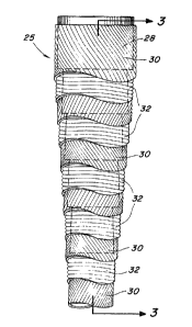
of the composite riser elemen-t of the present invention
showing various layers of composite material, and
Figure 3 is a cross-sectional view of the composite
riser shown in Figure 2 taken along lines 3-3 thereof.
Detailed Decription of the Preferred Embodiments and the
Drawings
Referring now to the drawings wherein the several
figures are presented for illustrating a preferred emodiment
of the invention only and not for the purpose of limiting
the scope of the invention, Figure 1 shows an offshore
tension leg platform 10. The TLP 10 generally comprises
a platform 12 floating in a body of water 14 and which
is anchored to the bottom 16 of the body of water by a
plurality of tensioned mooring elements 18 which extend
between the floating platform 12 and anchoring means 20
which are located on the bottom 16 of the body of water
14. The anchoring means 20 are adapted for connection
of a plurality of tensioned mooring elements 18 and are
secured in position by plurality of pilings extending into
the bottom 16.
,
'
~ 28518~
The tensioned moorlng elements 18 comprise a
plurality of tubular joints 22 which are interconnected
at their ends by a plurality of connector means 24. The
tensioned mooring elements 18 are maintained in constant
tension between the anchoring means 20 and the floating
platform 12 by buoyancy of the floating platform 12 which
is constantly maintained in excess of its operating weight
under all conditions.
The tension leg platform 10 also includes a plur-
ality of well risers 25 extending from a subsea template
26 to a well deck 27 located on the floating platform struc-
ture 12. In normal TLP operations, the well risers 25
are each provided with some form of motion compensation
in order to maintain tension on the well risers 25 and
prevent compression buckling thereof due to platform motions.
In the past, such well risers 25 have been made of tubular
steel and the riser tensioners generally comprising a complex
system of hydraulic cylinders have a piston stroke long
enough to accomodate any platform motions while maintaining
the required tension on the well risers 25.
The present invention provides a means for re-
placing the common tubular steel well risers with a tubular
composite having low axial stiffness which, by its somewhat
elastic nature, permits direct connection of the well risers
25 to wellheads secured to the well deck 27 and permitting
the elimination of large heavy, complex, and costly riser
tensioning devices. In accordance with a preferred embodi-
ment of the invention, the well risers 25 comprise a tubular
composite of a plurality of substantially vertically oriented
aramid fibers in a resin matrix.
As shown in Figures 2 and 3, in accordance with
one preferred embodiment of the invention, a well riser
25 generally comprises a tubular composite structure in-
cluding a metallic connector 28 disposed at each end thereof.
Alternatively, integral connectors may be provided. The
well riser 25 may be a one piece structure extending the
~ ,
. : . ' ' .
,. .~ ' ,''
:.
-: : , , ' .
~ 285~37
6 --
entire length between the template 26 and the well deck
27. Alternatively, the well riser 25 may comprise a plur-
ality of interconnected joints utilizing metallic connectors
26 which may have a threaded design or be welded together
in order to form a continuous tubular riser 25.
In accordance with the invention, the composite
tubular well riser 25 comprises a plurality of layers of
generally longitudinally (small helix angle) extending
reinforcing fibrous material. In its preferred form, a
plurality of parallel-lay aramid fiber layers 30 have an
elastic of less than about twenty million psi. The fibers
are disposed in a thermoset or thermoplastic matrix. The
longitudinal fiber layers 30 are alternated with circumferen-
tially wound layers 32 of high strength, high twist angle,
helically wound aramid fibers having an elastic modulus
less than that of the longitudinal fibers 30 in the same
resin matrix. Proper selection of longitudinal and circum-
ferential fiber materials can insure that the length of
the riser is independent of internal pressure and fluid
temperature effects. It will be understood that the well
riser 25 may be constructed solely of aramid fibers in
a resin matrix in two-layer sets, with one set of
parallel-lay or a longitudinally oriented low-angle helical
twist layers and the other set with layers of circumferen-
tially wound aramid fiber. The circumferential winding
32 is present order to provide the hoop strength, toughness
and damage resistance to the composite structure. In its
preferred form, the aramid fibers have an elastic modulus
of less than about twenty million psi.
In the cross-sectional view of the well riser
25 shown in Figures 2 and 3, the layered form of the tubular
composite structure and one preferred form of metallic
connector 28 are shown. As can be seen, a plurality of
layers of longitudinally oriented aramid fibers 30 are
alternated with a plurality of circumferentially oriented
aramid fibers 32 all in a resin matrix to form the tubular
51~37
-- 7
composite well riser structure 25. It will be understood
that the size and number of layers of longitudinally and
circumferentially wound aramid fiber may be varied to provide
the desired strength and stiffness in the well riser 25.
The preferred metal connector 28 has a generally
radially stepped form to which the various layers 30,32
of fibrous material are bonded. In their preferred form,
the steps 34 of the metal connector 26 have a slight reverse
taper extending longitudinally away from the tubular com-
posite portion of the well riser 25 in order to increase
the strength of the connection for increased axial loading
capacity. Also as illustrated in Figure 3, the end portions
of the longitudinally oriented aramid fibers 30 abut against
the radially oriented faces 36 of the steps 34 whereas
the circumferentially wound aramid fiber layers 32 overlay
the land faces 38 of the steps 34. As previously stated,
the metal connector may be provided with threads in order
to engage coupling means for interconnection with various
other components of the well riser 25 or may include portions
which may be conveniently welded to other components.
The riser 25 is provided with both internal and
external elastomeric liners 40 and 42, respectively. The
liners 40,42 are provided to increase the chemical and
damage resistance of the riser 25. Additionally, the ex-
ternal liner 42 may, in its preferred form, include an
antifouling material such as particulate copper to prevent
marine growth and eliminate the need for expensive periodic
cleaning operations.
In forming the composite structure, several known
techniques may be used but filament winding is preferred.
In filament winding, the reinforcing fiber is wound onto
a mandrel in a helical or circumferential pattern repeatedly
to form the composite structure. The resulting structure
is then cured in an oven. Filament winding machines are
available to produce large composite parts. This technique
is useful for the fabrication of generated shapes such
'
: ,
.
~ ~8S~L~3'7
8 --
as rings, cylinders, and pressure vessels, even of variable
cross-section. Wet filament winding involves wetting the
fibers with uncured resin before winding on the mandrel.
Dry filament winding or tape winding employs "prepreg"
tapes of approximately one inch width. "Prepreg" tapes
or sheaths are fibers preimpregnated with uncured resin
and are more expensive than Eibers and resin purchased
separately. Winding of dry fibers with subsequent resin
injection is also possible.
The mandrels on which windings are preformed
can be of varying cross-section. Integral metallic end
fittings may be easily incorporated into a filament wound
product. Various fiber orientations except 0 can be
achieved by filament winding. Zero degrees plies may be
provided as prepregs which are laid up by hand. ~lterna-
tively, a longitudinal lay-down method may be used whereby
0 fibers are laid on a mandrel while being captured by
a 90 outer wrap.
While the invention has been described in the
more limited aspects of a preferred embodiment thereof,
other embodiments have been suggested and still others
will occur to those skilled in the art upon a reading and
understanding of the foregoing specification. It is intended
that all such embodiments be included within the scope
of this invention as limited only by the appended claims.
'
; .
' ' ,` '