Note: Descriptions are shown in the official language in which they were submitted.
5 fi~(~
LIGHT-DRIVEN PHASE SHIFTER
BACKGROUND OF THE IN~ENTION
This invention generally relates to modulating a
carrier wave for signal transmission and, more
particularly, to phase/frequency shifting a light beam for
use in optical signal transmission.
Electromagnetic radiation in the optical frequency
range is being increasingly used as a carrier signal for
information transmission. Electromagnetic carrier signals
~; ; 10 may typically be amplitude modulated or frequency modulated
to transmit information with the carrier. Where the
carrier is a light beam, various electrooptic devices have
been used to modulate the carrier signal. It will be
understood that frequency modulation involves a frequency
change or phase shift in the carrier signal.
One conventional device for intensity, or amplitude,
modulating a light beam is a Pockels cell. Crystals are
-~ ~ provided which undergo a ~change in the refractive
characteristics in an applied electric field. A relatively
high voltage drive;r is required to activate the crystals.
Further, carrier intensity is limited by temperature
sensitivity of the crystals which exhibit the
~: .
'.
` '-
4~
Pockels effect and the carrier siynal may be attenuated
whil~ traver~inq the modulator. Further, the ~rystal
res~ons~ times are limited, thereby limi~ing the
informatio~ content which ca~ be transmitted and the r;se
t;m~ pulse capability.
Yet another modulating device for ligh~ beam~ uses th~
Paraday effect. I~ this e~fect ~he polariza~ion of a
light beam can be rotated ~hen it passes through material
in the directio~ o~ an applied ma~netic field. With the
magnetic field the operating frequencies and pulse ri~e
times are limited by inducti~s affects. Again, the
carrier light beam is limited in power and
in~ormation-carrying ca~ability.
These and other problems of the ~rior art are
addres~ed by the present device and an improved light beam
carrier phase shifter is provided for ~ignal carriar
transmissio~. Accordingly, one object o~ the ~resent
invention is to obtain a wide ra~ge of signal modulation
capability.
Another object of ~he present invention is to decrease
the riæe time for a modulating pulse.
Yet another object is to enabls increased power
capa~ility for ~he carrier ~i~nal.
One other object i6 to enable relatively low-~oltage
drivers to be used in the modulating sy~tem.
Additional objects, advantages and novel features of
the ~nvention will be set forth in part in ~he description
which follows, and in par~ will become apparent to those
skilled in the art upon examination of the following or
may be learned by practice of the inven~ion. The objects
and advantages of the invention may be realized and
attainsd by means o the instrumentalities and
combination~ particularly pointed out in the appended
claims~
:
, .
SUMM~Y OF_THE INVENTION
To achieve ~he foregoing and othsr ob3ects, and in
accordance with the purposes o the presen~ invention, as
embodied and broadly described herei~, the apparatus of
this invention may com~rise a light-driven phase shifter.
A modulating chamber ~s ~rovided having a yas with at
least three electron energy states i~cluding a ground
state, a metastable state, ana a transition state having a
transition energy from the metastable ~tate which
correspond~ to a first light wavele~g~h. A ~irst light
means illuminates the modulating chamber with modulating
light at the first waveleng~h along a first beam path, the
first beam path defini~g a volume of the gas ha~ing an
index of refraction determinable by an intensity of the
first light beam. A second light beam then illuminates
the modulating chamber with a transmission light bea~
along a second beam path traversing at le~st a portion o~
the first beam path. Means for Yarying the intensity of
the first light beam is provided which i~ effective to
vary the gas index o~ re~raction for phase shifting ~he
transmission light beam.
In another characterization of the present i~Yentio~,
a light-driven phase shifter is provided having a gas
volume with a medium excitable by ~ selected wavelenqth
2S light to a transition state. ~odulating means forms a
first path of the light at ~he selected wavelength at a
variable intensity through the gas volume. A transmissio~
means forms a second path of a second light at a
selectable frequency throu~h the qas volume and at least
partially ~oincident with the first ligh~ path.
In one other characterizat;on of the present
: inven~ion, a light-driven phase shifter is provided with a
eirst lase~ means having a selected wavelength light for
.
1~ ;4~
def ining an optical path with a variable index o
refractio~ functionally related to an intensity of the
selec~ed wavelength light. A second las~r means is
aligned to traverse at least a portion of the optical path
for phase shifting by the variable inde~ of refractio~.
Still another characterization o~ the present
invention includes a light-driven phase shifter w;th a
medium ha~ing at least three electron energy ~ates wi~h
relaeiv~ populations furlctionally related to an exciting
laser intensity. Modulating means generate~ the exciting
laser with a variable irltensity to def ine a f irst light
path within the medium. Siqnal carrier means generates a
second laser along a second light path which is at least
partially coincident with the f irst light path for
introducing a phase shift by varying th~ medium index o
refraction as the relative state populations vary with ~he
intensi~y o~ the exciting laser along the first light path.
BRIEF DESCRIPTION OF THE_DRAWINGS
The accompanying drawings, which are incorporated in
and ~orm a part of the spe~ification, illustrate the
embodiment of the present invention a~d, together with the
descri~tion, serve to explain the principles of the
inven~ion. I~ ~he drawings:
FIGURE l is a representative three leYel electron
state diagram.
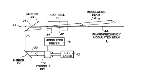
FIGUR~ 2 is a schematic representation of a light
dri~en phase shif~er according to one embodiment of the
present invention.
DETAILED_DESCRIPTION OF TH~ INVENTION
~n a pref~rred embodimen~ of the ~resent invention a
phas~ shifter is provided for a ligh~ beam carrier signal
where the ~hase shift is based on the variation o~ ~he
rePractive index of a gas medium by use o~ resonant laser
.
~56f~
light to alter the electron energy state populations of
the gas atoms. The index o~ refraction of the gas medîum
is functionally related ~o the elecSron ~opulations o~ the
energy ~tate levels available for the gas. These
populations are, in turn, determined by the inten~ity of
an exciting light beam. The exeiting light beam frequency
is selected to move electrons fro~ a metastable fitate to a
tran~ition state which decays to a ground 6tate. Thus,
~he population levels, and hence the index of refraction,
can be modulated ~y varying the inten~ity o~ the
modulating light beam.
The wavelength of a ~econd light beam incident on the
excited gas medium is inversely related to the index of
refraction. H~nce, as hereinafter described, the number
of wavelengths along a predetermined path including the
excited gas will vary as the wavelength Yaries, induci~g a
phase shift through the gaseous path ~raversed by the
second light beam~ ~urther, if the index of refractio~ is
now varied with time a frequency shi~t in the second ligh~
beam can be induc~d to frequency modulate the second beam.
P~ASE SHIFT
It can be show~ that a light beam passing through a
medium can be phase and frequency shifted ~y varying the
index of refraction of the medium. Let:
L , length of o~tical path in medium:
~acuum wavele~gth of light beam;
n , index of re~raction of medium;
N~ = number of wavelengths within gas cell:
~ = wa~elength in medium ~ n
Then,
k nL
~,,, =
,
~L2~ i41EI~
~N~ n
The phase change, a~. alon~ ona wavelength is
radia~s, or ~ ~ 2~oN~.
Along the medium,
~ou~ ~ ~in a 2~N~ = 2~ ~n
dt dt ~out ~in
~ 2~ (~out ~ Vin)
= 2~ ~v
where
~ - angular speed
v = frequency
Therefore,
~ n ~1)
and
~v ~ ~ ~t (2)
REFRACTIVE INDEX VARIATION
Re~erring irst to Figure 1 there is depicted a
simplified energy level diagram of an element having four
elec~ron fitates. A suitable gas medium ~as at lea t a
: 20 metastab}e state (level 1~, a transieion state (level 2~o
: and a ground state (level 3). One or more alternate
energy levels (e~g. level 4) may be available. but wi~h a
relatively ~table poyulation~ ~a~ herein described.
: lectrons may move between level 1 and level 2 by
excitation and by decay and fro~ level 2 to level 3 by
~ decay. Llkewise, electrons may be moved from level
:: ::
:: :
~ 2~
ground state ~o level 1 metastable state by radio
frequency or dc excitation. It should be apprecia~ed that
at least a three-s~a~e system is required to obtai~
variable state populations si~ce the state populations i~
a two-state system ~end to equalize as the absorbing state
obtai~s ~ substan~ially steady state condition. As show~
in Figure 1, a ~tate change from level 1 to level 2 can be
produced by supplying light at wavelength at ~l 2
~roviaing photons at an energy correspondiny to the
dif f erence in energy betwee~ level l and level 2.
Assuming initially that all atoms are in the
metastable state ~level l) the refractive index is now
expressed as~
n2~ t3)
where
fln = oscillator strength of transitions connecting
metastable state 1 with higher state le~els
~ln ~ wavelength of ~ransitio~
~ = wavelength of light at which the refrac~ive
index is being measured
~l = fraction of atoms in state l
N = ~umber density of atoms in gas or vapor
~O _ permittivity of free space
e = electron charge
m - electron mass
c = speed of light in ~acuum -~
.
This eon~entional formulation i5 derived ~rom the
respons~ of a~ ato~ic dipole oscillator of resonance
waveleng~h, ~ , to electromagnetic radiation of
wavelength, ~. The fiummation ~n Equation 3 i3 over all
possible transition bet~een the metastable state (level
1) and higher levels, 8UC~ as level 2 and level 4.
Transition ener~y wavelengths are labeled ~ where
the firs~ indice designates the lower state and ~he second
indice designates the upper level.
If laser light of wavelength ~1 2 is applied,
resonant with a transi~ion energy from a metastable 6tate
(level 1) to a hi~her level transition, the higher
transitio~ will be populated. In the exAmple, the
exciting laser light has a wavelength ~1 2 to cause
level 2 to be ~opulated. Further, if level 2 has a sho~t
lifetime, i.e., several nanoseconds, and a strong decay
path to the ground state (level 3), an inversion occurs
wherein the metastable state (level 1) is depleted and the
ground state (level 3) is populated.
The net result o~ this application o~ refionant
wa~elength light ~1 2 Erom a laser is the depletion of
the metasta~le state and the production of a gaseous
medium in which all of the atoms exposed to the exciting
laser light are now returned to the ground state. The
rate of this depletion process is a function of the
intensity of the laser li~ht and the transition rate
between le~els 2 and 3. With all of the atoms now in a
ground state along the path of the exciting laser light,
the index of refraction can now be written as:
n2(~ 3 3 ~ ~4)
i4~
where
~3 - fractio~ o~ atom in ~tate 3
f3 ~ ~ oscilla~or ~tre~g~hs of transi~ions from level
3 to hi~her levals
wavelength o~ transitions from level 3 to
nigher levels.
Equation 4 can be simpli~ied since n i8 typically
~ery close to l:
o l~rZ~ ~Z n ~2 ~ Lacer Light OFP ~s)
n1 = 1 + ~ ~ ~ ~m ~ Laser Li~ht ON ~6)
The to~al change in the refractive index between laser
light OFF and laser light ON i8 given by:
an 8 ~o - nl ~ Ne2 ~ ~l fln _ ~3 f3m l (7)
:~ 16~2 m~2 Ln ~-2 _ ~-2 ~32 _ ~-2J
as previously shown).
: ~ L
It should be noted that there may exist many
metastable levels other than metastable level l, but their
contribution to the change in refractiv index cancel
` : since~ the : state populations are unaltered where the
; : incident laser light i~ not resonant with a transition
;~ 20 energy. Thus, the problem is reduced to a simple
~ three-level system.
~ ~ -
:
' . ,
, ' ' : '
- ' ' ~ -
D
To show the dependenc2 of the index o~ refractio~ on
inciden~ light intensity, Equa~ion 7 can be further
r~duced:
Since ~1 + ~3 ~ 1 (only levels 1 and 3 ca~ be
populated signi~icantly)
1 ~ ~1'
~ubstituting into Equation 7 gi~e~
~N~ ~ ~L Ne ~ 3m _ (B)
16~ ~Omc ~3m ~ ~
~ ln + E f3m ~1
~ 1 ~n ~-2 ~-2 m ~-2 ~-2~ ~
Since ~land ~3 are time dependent, we can differentiate to
get phase ~hift/unit time:
dN,A L NeZ ~d~ ) (9)
d'c ~ 161t2FomC L
f3m
~n ~-2 ~ -2 m ~-2 ~-2~
: To determine the rate of cha~ge o~ the relative
IS populatio~ of the metastable state (lavel 1), recall that:
~ 1 + ~2 ~ ~3 ' 1
whe~e ~ 2~ ~3 are tha population factors for the
three-level proble~. Differentiating and reco~bining terms
'
;~ ' ~' ' - ' ' .
-
~L2
qives:
dt (dt ~ dt ) (lO~
Also,
d~2 Sl
~ B12 ~ ~2~21 ~2 23 gl (11)
5 where
~B12 , rate of pum~ing atoms from sta~e 1 ~o
stat~ 2 through stimulated ahsorption
~1 = ractions of atom~ in state 1
~ = power density of applied laser light
10 B12 = Einstein B coefficient for stimulated
ab~orptio~
A21~2 ~ rate of decay of level 2 back to ground
state 1
A21 = decay rate for 2~1 transition
15 ~ = fraction o~ atoms in 6tate 2
A23~2 3 rate o decay of level 2 to level 3
Az3 ~ decay rate of 2~3 transition
92 ~2~B21 = rate of ~timulated emission from level
2 to le~el 1
20~21 = Einstein B coefficient for stimulated
emission
2 = degeneracy factors
.
~`
12and,
dE3 1 d~3
dt ~ ~2A23 or ~z ' A23 dt (12)
Substituting 2quation 11 and Equatio~ 12 into Equation 10,
and re~riting, gives:
d~l 1 d~3 gl /d~3\ ~B
dt 3 ~ ~7~Bl2 + A2 dt g2 ~dt ) ~ 23 tl3)
Y' 21 ~23 and ~B21 ~23~ and ~quation
13 simplifies to:
d~l
d~ B12 (14)
Now the exciting laser light o~ wavelength ~1 2 is
- 10 depleting the metastable state (level 1) a~ a rate equal
to the absorption rate o~ the laser ligh~.
Then. ~ = ~zlc '
where
I = time a~eraged laser light intensity
g(v) , homogeneously broadene~ linewidth
21 _ 2
~[~v2~ + ~ -1) ] ~A21 at resonance ~Au - O).
Also, ~ - 4hcl' where
= center wa~eleng~h of applied laser light.
h = Planck's constant
.
,
i2~i~
13
Substitutinq i~to Equ~tio~ (14),
d ~
dt ~l 2~hc I ~15)
Thus, the rate .of change o~ the level l populatio~
decreases linearly wi~h the in~ensity of the applied laser
light. It will be appre~iated that ~he len~th of ~he
optical path does not become a ~actar since the laser beam
"burns" a hole through the absorbing mediu~ where the
absorption state is depleted. Thus, the absorption length
of the medium for the excitin~ laser light becomes
relatively long and long gas cell lengths ea~ be used.
The final expression for the cha~ge in phase with ~ime
is then given by substituting Equa~ion (15) into the basic
phase change ormula, Equatio~
d~ ~ dN~ L NeD~2 [ 1 2~hc] (16)
~ + m ~ ~ ~ 21
DETAILED DESÇRIPTION OF THE_PREF~RRED EMBODIMENT
Referring now to Figure 2, there is show~ a phase
shi~ting modulator in block diagram form. A firs~ light
source 12, which is preferably a ~unable dye laser, is
provided a a modulating light beam. Dye laser 12 is
selected for resonance with a metastable-~ransition state
energy difference for the gas in gas ~olume 32. Pockels
cell l4 is drive~ by modulator driver 16 to vary the
intensity oF the output of dye laser 12.
.' ~' -' ;' ` '
~ : .
14
The variable intensit~ output laser beam 22 may then
be direc~ed throu~h gas cell 32 by reflection from mirror
24 and mirror 26 and hence through gas ~oluma 32.
suitable gas cell 32 would have a length of about 10 cm
with windows at each end, using a suitable excitable
gaseous medium selected ~rom the noble gases, e.g.,
argon. The gaseous mediu~ defines a first index o~
refractio~ when the medium has been excited to populate
the metastable state and when output laser ~ea~ 22 is OFF.
When outpu~ laser beam 22 is ON, bea~ 22 with a
wavelen~th f ~1 2 defines a first optical path 34
through ga~ cell 32. The energy states of gas a~oms along
~irst optical ~ath 34 ar~ populated a~d define a second
index of refraction along first optical path 34, as
hereinabove described. Diffusion of the gas atoms within
gas cell 32 provides a resupply of ~as with a populated
metastable state when laser beam 22 is OFF.
A second light beam 38 may now be ~ransmit~ed through
an opening 2a in mirror 26 and ~hrough gas cell 32. The
20 second light beam 38 is a sig~al carrier beam which has a
wavele~gth different than modulating laser beam 22 and may
be of relatively hiyh power for transmission over long
distances. First optical path 34 is sliqhtly axially
divergent from second optical path 42 such that second
optical path 42 is preferably within first op~ical path 34
when traversing gaseous mediu~ 32.
The intensity o~ modulating light beam 22 varies the
index of refraction of gas cell 32 along first optical
path 34. This variation i8 a high frequen~y response and
enables a pulsed phase shift to be obtained having short
rise ti~es. Further, con~entional modula~ors such as the
Pockels cell or a Faraday ef~ect device have limited phase
modulation of one radian or less. Apparaeus herein
~2~
described is e~pected to have a phase modulation
capability of lO-lOO radians. The ~ansmit~er light bea~,
or carr~er signal light beam 3a, i the~ phase shifted and
hen~e frequency modulated by intensity modulation of
modulating laser light beam 22.
Then, power absorption within gas eell 32 is only ~ro~
the modulating li~h~ beam 22, which may be relatively low
power. Further~ the state transition~ of the ga~ atoms
occur in a time which is short relative to the desired
modulation to enable modulation in the l ~sec ~ime
frame. A high power, high requency optical signal system
is provided.
The foregoing description of the preferred e~bodiment
of the invention have been presented for purposes of
illu~tration and descriætion. It is not intended to be
exhaustive or to limit the invention ~o the precise form
disclosed, and obviously many modification~ and variations
are possible in light of the above teaching. The
embodiment were chosen and described in order to best
explain the principles of the inve~ion and i~s practical
application to thereby enable o~hers 6killed in the ar~ eO
best utilize the invention in various embodiments and with
various modifications as are suited ~o ~he particular use
Gontemplated. It is intended that the ~cope of the
invention be defined by the claims a~ended hereto.