Note: Descriptions are shown in the official language in which they were submitted.
7~
TITLE O]' THE INVENTION
Langmuir-Blodgett Ultrathin
Membrane of Ployfumarate
BACKGROUND OF THE INVENTION:
Field of the Invention;
This invention relates to a polymer
Langmuir-Blodgett ultrathin membrane, hereafter abbreviated
to LB membrane or LB ultrathin membrane. More particularly,
it relates to a smooth and homogeneous LB membrane
constituted of polyfumarate.
Related Art Statement;
As the methods for preparing a smooth and
homogeneous organic ultrathin membrane having a uniform
molecular orientation, it has been customary to use a
Langmuir-Blodgett method, referred to herein as the LB
method. The LB me-thod means a vertical dipping method
according to which a dilute solution of organic solvents
immiscible with water is prepared and spread on a clean
water surface, a gaseous membrane which is left after
vaporization o~ the solvent is compressed in a horizontal
direction to form a solid membrane with the molecules packed
tightly together, and then a solid subs-tra-te pl~te is moved
ver-tically with respect to the horizontal plane for
transferring and stacking the solid membrane in plural
layers on the surface of the solid substrate plate. The
ultrathin film formed in this manner on the substra-te is
-
s~
called the LB membrane, see for instance the 1iterature by
K.B.Blodgett, JACS., 55, 1007 (1935). On the other hand, a
horizontal lifting method has also been evolved according to
which the layers of the solid membrane is transferred by
vertically moving the subs-trate plate so that the substrate
plate is horizontally con-tacted with the surface of the
solid membrane, see the literature by K. Fukuda, J. Col:Loid
Interface, 54,430(1976). Currently, the ultrathin membrane
formed on the substrate plate by the horizontal lifting
method is also called the LB membrane. It is a feature of
both the vertical dipping and horizontal lifting me-thods
that a smooth and homogeneous membrane wi-th a desired
thickness and a uniform molecular orientation may be
produced and that the produced membrane may range from an
ultrathin membrane of the thickness of the order of a
molecular thickness, e.g. monomolecular layer to a
multilayered membrane of desired thickness produced by
repeatedly transferring the monomolecular layers.
Alternatively, electrical elements such as
varistors, thyristors, diodes, photodiodes, light emitting
diodes and transistors as well as LSIs composed of these
electrical elements, may be basicaly classified into
metal/insulator/metal (MIM), metal/insulator/semiconductor
(MIS), metal/semiconductor or Schottky element (MS),
semiconductor/semiconductor(SS; p,n-junction) and
semiconductor/insulator/semiconductor (SIS). The MIM, MIS
~2~357'3~
and SIS elements need be Eormed with insulator layers and
are usually prepared by oxidizing the surface of an aluminum
or beryllium substrate or a silicon substrate to form an
insulating film of reduced thickness of SiO2 or metal oxide
followed by formation of a counter electrode. However, this
technology cannot be adapted to metal or semiconductor
substrates other than the abovementioned substrates. The
adaptation to versatile MIS type elements such as diodes,
photodiodes, light emitting diodes or field effect
transistors is not possible when using inter alia
semiconductors other than Si, including compound
semiconductors. Therefore, all possible combinations can be
achieved by using an organic insulating ultrathin membrane
as the insulating layer. It is required that such
insulating ultrathin membrane be of a thickness of not
higher than 50 A and preferably not higher than 20 A while
being smooth and homogeneous. Accordingly, it has been
tried to apply the above described LB membrane as the
electrical element.
As a typical example of such trials, formation of
the I.B membrane of straight-chain fatty acids having not
less than 16 carbon atoms, or alkaline earth metal or
cadmium salts thereof, has been considered extensively, sse
for example G. G. Roberts: IEE, Proc. Solid S-tate Electron
25 Device, Vol.2, pl69, 1978. However, the LB membrane of
these fatty acids or metal salts -thereof are low in
mechanical strength and heat resistance and therefore cannot
be used practically. Accordingly, it has been suggested to
form the polymerizable fatty acid into an LB membrane prior
to polymerization followed by polymerizing the membrane or
to polymerize on the water surface followed by forming an LB
membrane. With the former method, however, the membrane is
frequentl~ constricted or cracked during polymerization.
With the latter method, difficulties are encounted in
setting the polymerization conditions and, above all, in
transferring the membrane onto the substrate surface by the
vertical dipping or horizontal lifting methods. Thus, it
has been desired to produce a polymer LB membrane superior
in mechanical strength and heat resistance.
In general, a soft linear chain high molecular
material forms more or less introcately entangled strands in
any dilu-te solution and is not suitable for being formed
into LB membranes since gaseous membranes are no-t formed
when spreading out the solution on the water surface. As an
exceptions, an LB membrane of polypeptides and (~ -olefin)-
maleic anhydride alternating copolymers have been reported,see the literature by J. H. McAlear, VLSI Tec., Digest of
Tec. Papers 82(1981); C.S. Win-ter et al, IEE Proc., Part I,
Solid State Electron Devices, 130, 256(1983); and R.H.
Tredgold et al, Thin Solid Films, 99, 81(1983). However,
the former material is soluble only in a special
mul-ti-component solvent such as chloroform/trichloroacetic
acid/methanol while trichloro acetic acid used as the essential
component for maintaining the solubility is highly likely to
deteriorate the metal surface used as the substrate. The latter
material corrodes metal or semiconductor surfaces.
The present inven-tion provides a polymer Langmuir-Blodgett
ultrathin membrane which is smoo-th, homogeneous and superior in
mechanical strength and heat resistance, a method for preparing
such membrane, and an electrical elemen-t including sùch membrane.
The present invention also provides a polymer Langmuir-Blodgett
ultrathin membrane superlor in moisture- and weather-resistance,
transparency and insulating properties, a method for producing
such membrane and an electrical element including such membrane.
The present invention again provides a polymer Langmuir-Blodgett
ultrathin membrane that is free of membrane constriction or crack
iormation and that can be laminated to a desired thickness, a
method for producing such membrane and an electrical element
inclu~ing such membrane.
According to the present invention, there is provided a Langmuir-
~lodgett ultrathin membrane constituted
-- 5 --
of polyfumarate hav.ing a degree of polymeriza-tion of 20 -to
10,000 and obtained by polymerizing fumarate represented by
the general formula of-
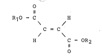
R1O - C H
C = C
H C ~ OR2
~ herein R1 and R2 represent the same or different
groups and at least one oE R1 and R2 represents a
hydrocarbon group selected from the group consis-ting of a
branched alkyl group having 3 to 12 carbon atoms, a
cycloalkyl group having 3 to 12 carbon atoms, a substi.tuted
alkyl group having 2 to 6 carbon atoms and containing a ring
structure substituent having 3 to 14 carbon atoms, and a
substituted cycloalkyl group having 3 to 10 carbon a-toms and
containing a substituent of the same ring structure as the
ring structure substituent; trifluoromethyl,
pentafluoroethyl, heptafluoro-n-propyl or a
fluorine-substituted hydrocarbon group obtained by
substituting at least one of hydrogen atoms of the
hydrocarbon group with a fluorine atom; a hetero
atom-containing hydrocarbon group containing in the
hydrocarbon group a hetero atom selected from the group
consisting o:E nitrogen, oxygen, phosphorus and sulfur atoms
and not containing mobile hydrogen atom or atoms; or an
organosilyl group, an organosilylalkyl group, an
organosiloxanyl group, an organosiloxanylalkyl group, an
organosiloxanylsilylalkyl group or an
organosiloxanyloxysilylalkyl group, each having 1 to 8
silicon atoms.
According to the present invention, there is also
provided an electrical element including the aforementioned
Langmuir-Blodgett ultrathin membrane as an insulating layer.
According to the present invention, there is also
provided a process for preparing a Langmuir-Blodgett
ultrathin membrane comprising the steps oE:
dissolv.ing the aforementioned polyfumarate in a
vaporizable organic solvent immiscible with water -to produce
a polyfumarate solution having a concentratlon of not higher
than 10 mg/ml;
spreading out the polyfumarate solu-tion on a clean
~ater surface to produce a gaseous membrane having a surface
pressure of not higher than 1 dyne/cm;
horlzontally applying a pressure to the gaseous
membrane to produce on said water surface a monolayer solid
5 membrane having a surface pressure of 10 -to 30 dyne/cm; and
transferring the monolayer solid membrane onto a
32
substrate plate.
BRIEF DESCRIPTION_OF T E DRAWINGS:
Fig.l is a chart showing surface pressure-surface
area curves for various polyfumarates employed in -the
present invention;
Fig. 2 is a chart showing current density-electric
potential characteristics for a thyristor at 20C according
to the Example 2; and
Fig.3 is a chart showing current densi-ty-electric
potential characteristics for a MIS type elemen-t of Example
11 in the dark and in the light, that is, under the white
light of 0.4 mW/cm2.
DESCRIPTION OF THE INVENTION:
According to the present invention, a polyfumarate
lS is used which is obtained by polymerizing fumarate
represented by the following general formula:
o
R1O ~ C H
C = C
H C - OR2
o
In the above formula, Rl and R2 represent -the same
or diEferent groups. At leas-t one of Rl and R2 may
represent a hydrocarbon group selected from the group
consisting of a branched alkyl group having 3 to 12 carbon
atoms, a cycloalkyl group having 3 to 12 carbon atoms, a
~ 35732
substituted alkyl group having 2 to 6 carbon a-toms and
containing a ring structure substituent having 3 to 1~
carbon atoms, and a substituted cycloalkyl group having 3 to
10 carbon atoms and containing a substituent oE the same
ring structure as the ring structure substituent. At leas-t
one of Rl and R2 may represent trifluoromethyl,
pentafluoroethyl, heptafluoro-n-propyl or a
fluorine-substituted hydrocarbon group obtained by
substituting at least one of hydrogen atoms of the
hydrocarbon group with a fluorine atom. At least one o~ R
and R2 may also represent a hetero atom-con-taining
hydrocarbon group containing in the hydrocarbon group a
hetero atom selected from the group consisting of nitrogen,
oxygen, phosphorus and sulfur atoms and not containing
mobile hydrogen atom or atoms; or an organosilyl group, an
organosilylalkyl group, an organosiloxanyl group, an
organosiloxanylalkyl group, an organosiloxanylsilylalkyl
group or an organosiloxanyloxysilylalkyl group, each having
1 to 8 silicon atoms. At any rate, it is required that one
of the groups Rl and R2 represents at least the
aforementioned group and, insoar as such condition is
satisfied, the other group may be any other hydrocarbon
groups, such as straight-chain alkyl or alkenyl groups or
any other organic residues having a cyclic structure, such
as an aryl group.
The speci~ic examples oE fumarate wherein Rl and/or
732
R2 represent the aforementioned hydrocarbon groups include
dicyclohexyl fumarate, dicyclopentyl fumarate,
isopropylcyclohexyl fumarate, ethylcyclohexyl fumarate,
sec-butylcyclohexyl fumarate, t-butylcyclohexyl fumarate,
allylbenzyl fumarate, cyclohexylbenzyl fumarate,
di-isopropyl fumarate, isopropylbenzyl fumara-te,
isopropylphenyl fumarate, cyclohexyl phenyl fumarate,
di-isobutyl fumarate, tert-butyl-methyl fumara-te, tert-
butyl-ethyl fumarate, tert-butyl-iso-propyl fumarate,
ter-t-butyl-n-propyl fumarate, -tert-butyl-n-butyl fumarate,
tert-butyl-iso-butyl fumarate, tert-butyl-sec-butyl
fumara-te, di-tert-butyl fumarate, tert-butyl-cyclopentyl
fumarate, tert-butyl-cyclohexyl fumarate, tert-butyl-2-
ethylhexyl fumarate, tert-butyl-biscyclohexyl fumarate,
tert-butyl-benzyl fumarate, tert-butyl-phenetyl fumarate,
tert-butyl-~-phenetyl fumarate and di-iso-pentyl fumarate.
The specific examples of fumarate wherein the group
R1 and/or R2 represent trifluoromethyl, pentafluoroethyl,
heptafluoro-n-propyl or a fluorine-substituted hydrocarbon
group obtained by substituting at least one of the hydrogen
atoms of the aforementioned hydrocarbon group with a
fluorine atom, include perEluorooctylethyl-isopropyl
fumarate, trifluoromethyl-isopropyl fumarate,
pentafluoroe-thyl-isopropyl fumarate, and heptafluoro-
n-propyl-isopropyl fumarate.
The specific examples of fumarate wherein the group
3~
R1 and/or R2 represent a hetero atom-containing hydrocarbon
group containing a he-tero atom selected from the group
consisting of a nitrogen atom, an oxygen atom, a phosphorus
atom or a sulfur atom and no-t containing a group containing
a mobile hydrogen atom or atoms, such as primary amide,
secondary amide, hydroxy or thiol, include
cyanoethyl-isopropyl fumarate, glycidyl-isopropyl fumarate,
diethylphosphonomethyl-isopropyl fumarate, and
2-methylthioethyl-isopropyl fumarate.
lo The specific examples of fumarate wherein the group
R1 and/or R2 represent an organosilyl group, an
organosilylalkyl group, an organosiloxanyl group, an
organosiloxanylalkyl group, an organosiloxanylsilylalkyl
group or an organosiloxanyloxysilylalkyl group, include
methyl-(trimethyl-silyl)-fumarate, ethyl-(trimethylsilyl)-
fumarate, isopropyl-(trime-thylsilyl)-fumarate, cyclohexyl-
(trimethylsilyl)-fumarate, tert-butyl-(trimethylsilyl)-
~umarate, methyl-(trimethylsilyl) methyl-fumarate,
ethyl-~3-trimethylsilyl) propyl-fumarate, isopropyl-
(trimethylsilyl)methyl-~umarate, isopropyl-(3-
trimetylsilyl) propyl-fumarate, isopropyl- {3-tris-
(trimethylsiloxy)silyl} propyl-Eumarate, isopropyl-3-
{methylbis(trimethylsiloxy)silyl} propyl-fumarate,
t-butyl-(trimethylsilyl)ethyl-fumarate, t-butyl-3- {tris-
(trimethylsiloxy)silyl} propyl-fumarate, t-butyl-3-
~(heptamethyl)trisil.oxanyl} propyl-fumarate, 2-e-thylhexyl-
3-(trimethylsilyl)propyl-Eumarate, 2-ethylhexyl-3- {tris-
(trimethylsiloxy)silyl} propyl-fumarate, 2-ethylhexyl-3-
{(pentamethyl)disiloxanyl} propyl-fumarate, cyclohexyl
~(trimethyl)silyl} methyl-fumarate, cyclohexyl-3- ~tris-
(trimethylsiloxy)silyl} propyl-fumarate, isopropyl-3-
{(pentamethyl)disiloxanyl~ propyl-fumarate, isopropyl-3-
~ {tris (pentamethyl)disiloxanyloxy~ silyl) propyl-
fumarate, cyclohexyl-3-( ~tris(pentamethyl)disiloxanyloxy}
silyl) propyl-fumarate and t-butyl-3-({tris(pentamethyl)
disiloxanyloxy} silyl) propyl-fumarate.
In preparing polyfumarate of the present invention,
the conventional radical polymerization process is selected.
The polymerization initiators used in the polymerization may
include one or more of azo compounds and organlc peroxides
having a decomposition temperature of not higher than 120C
at selected half-life value for 10 hours.
These initiators may be enumerated by benzoyl
peroxide, diisopropyl peroxycarbonate, t-butylperoxy
-2-ethyl hexanoate, t-butylperoxypivalate, t-butylperoxy
diisobutylate, lauroyl peroxide and azobisisobutyronitrile.
The polymerization initiator may be used preferably in an
amount of not larger than 10 wt. parts and more preferably
in an amount of not larger than 5 wt. parts to 100 wt. parts
of the starting monomer.
According to the presen-t invention, polyfumarate
having a degree oE polymerization of 20 to 10,000 is used.
~ 2:~3573~
IE the degree of polymerization is less than 20, an LB
membrane insufficient in mechanical strength and heat
resistance is obtained. On the other hand, it is difficult
to prepare a polyfumarate having a degree of polymerization
of more -than 10,000~
In preparing polyfumarate, it is preferred that the
polymerization system be put under an atmosphere of an inert
gas, such as nitrogen, carbon dioxide or helium. The
polymerization temperature may be in the range of from 30 to
100C, depending on the kind of the polymeriza-tion initiator
employed. The total time necessary for polymerization may
be in the range of 10 to 72 hours.
Tha method for preparing the polymer LB membrane
using -the aforementioned polyfumarate is hereafter
explained.
The polyfumarate is first dissolved in a
vaporizable organ.ic solvent immiscible with water to produce
a polyfumarate solution having a concentration of not higher
than 10 mg/ml. This solution is then spread on clean water
surface for vaporizing the organic solvent. Examples of the
vaporizable organic solvent include chloroform, ethylene
chloride, ethylene dichloride and benzene. At the usual
operating temperature of 10 to 35C, chloroform is vaporized
modarately and hence is most preferred. As the operating
temperature becomes higher, it is preferred to use a higher
boiling solvent such as benzene or ethylene dichloride and a
73~2
more dilute solution. Since the polyEumarate of the present
invention has a glass transition temperature Tg or
decomposition temperature of not lower than 200C, it can be
formed into an LB membrane at a higher temperature reaching
70 to 80C. Therefore, not only the operating condi-tions
are wider but it also becomes possible to produce a mixed LB
membrane from a mixture containing functional molecules
other than polyfumarate, such as dyestuff, that may be
dissolved only at a higher temperature. Further, due to its
high transition temperature Tg, polyfumarate LB membrane is
not fabricated at the sub phase temperature (See Example ').
It is necessary that the polyfumarate concentration in the
organic solvent be not higher than 10 mg/ml and more
preferably in the range of 0.1 to 3 mg/ml. With the
concentration in excess of 10 mg/ml, the organic solvent is
vaporized off before the polyfurnarate solution is completely
spread out on the water surface, while droplets go into
water without being spread on the water surface due to
increased specific gravity. The sub-phase solution or
aqueous solution should be free of organic impurities and
its surface should be clean in order to prevent the impurity
from becoming affixed to or destructing the LB membrane.
However, the LB membrane of the invention is totally
insensitive to inorganic additives in a sub-phase such as
inorganic neutral sals, acids or bases.
Since the polymer LB membrane of the present
~2~ ~'3~
invention makes use of a specified polyfumarate having bulky
side chains or specified side chains including silicon
atoms, the polyfumarate is not in the from of en-tangled
stands when the organic solvent is spread on the water
surface and vaporized off but a gaseous membrane having a
surface pressure of not higher than 1 dyne/cm, that is, a
membrane having its molecules movable with the same degree
of freedom as the gas, is formed on the water surace.
Then pressure is applied in the horizontal
direction on the gaseous membrane thus spread on the water
surface and having the surface pressure of not higher than 1
dyne/cm for forming a monolayer solid membrane having the
surface pressure of 10 to 30 dyne/cm on the water surface.
For applying the horizontal pressure, a float having the
same width as the weir filled with water is placed on the
water surface and gradually moved in the predetermined
direction for applying the desired pressure on -the gaseous
membrane.
The value of surface pressure depends on the kind
of the polyfumarate employed. Thus, such an artifice may be
employed in which the surface pressure is set to that of the
acute rising portion of a previously obtained surface
pressure-surface area isothermal curve corresponding -to the
solid membrane phase. At any rate, the surface pressure of
the produced monolayer solid membrane should be in the range
of 10 to 30 dyne/cm.
73~
Then a substrate plate is contacted wi.th a
monolayer solid membrane floa-ting on the water surface for
transferring the monolayer solid membrane onto the subs-trate
surface. In this manner, the monolayer solid membrane
having -the thickness of approximately 10 to 11 A may be
transferred onto the substrate surface. Alternatively, the
monolayer solid membrane of the desired thickness may be
laminated on the substrate surface by repeatedly performing
the operation of vertically introducing the substrate into
the water and lifting the substrate (vertical dipping
method), or the operation of contacting the substrate plate
with the monolayer solid membrane on the water surface in
parallel with the water surface (horizontal lifting method).
According to the present invention, the membrane thickness
may range from about 10 A for a monolayer solid membrane to
the order oE microns or more for the multilayered membrane
produced by the repe-tition of the above described laminating
steps.
With the vertical dipping method, the up-down speed
of the substrate plate markedly influences the properties of
the produced LB membrane. With the fatty acid, for example,
defects in the membrane will become apparent unless the
up-down speed of not higher than 0.5 to 1 mm/min is used.
With the formation of the LB membrane from the fumarate of
the present invention, however, the solid membrane may be
transferred even with a rather high substrate plate speed of
16
~8~
10 mm/min. At least the defec-t of a size not less -than 0.05
micron has not been observed on the photo of the membrane
formed by 20 laminated layers of poly(dl-isopropyl)fumarate,
the photo being taken with a differential interference
contrast op-tical microscope having a magnification factor of
400 and enlarged to 1000 times for observation. Conversely,
larger defects of the order of 1 to 5 microns may be
sporadically observed on the LB membrane of cadmium
eicosanoate produced by transferring the layers laminated
under the same conditions. Although the LB membrane layers
of the present invention can be transferred at -the substrate
plate speed of not higher than lO mm/min, the speed oE not
higher than 5 mm/min is preferred in view of safety and the
speed of 2 to 3 mm/min is more preferred in view of
operability. With the horizontal li~ting method, it is
desirable that the substrate plate speed at the instant
that the solid membrane on the water surface contacts the
substrate plate be controlled so as to be not higher than 5
mm/min and preferably in the range of 1 to 3 mm/min.
With the vertical dipping method, almost any
metals, plastics, ceramic materials or water-insoluble
inorganic solid crystals such as fluorspar (~aF2~ may be
used as the substrate material, with the excepti.on of
strongly hydrophilic material, such as polyvinyl alcohol or
polyacrylamide or poly(tetrafluoroethylene). The layers can
also be transferred on poly(tetxafluoroethylene) by the
j7~:12
horizontal lifting method. It is only sufficien-t that the
substrate presents a mirror surface free rom grinding
traces on observation with nacked eyes.
The LB membrane of the present invention produced
in this manner may be used as an insulating layer for a
number of electrical elements. In this case, the substrate
may be formed of silicon, germanium, nickel, iron, cobalt,
copper, platinum, gold, rare earth metals, metal oxides, or
metal oxide semiconductors such as SiO2, NiO, SnO2, In2O3,
indium tin nesa glass (Hereinafter referred to as ITO nesa)
or tin oxide nesa glass (Hereinafter referred to as nesa),
compound semiconductors such as galium arsenic, gallium
phosphorus or indium phosphorus, chalcogensl e.g. selenides
or sulfides of transisition metals, such as æinc selenide or
zinc sulfide, chalcogenides of WO3 or VO2, polycarbonates,
polyethylene terephthalate, polyethylene or polypropylene,
but these specific examples do not limit the present
invention.
The electrical element including the polymer LB
membrane according to the present invention may be obtained
by ~orming on the LB membrane on the substrate a conducting
or semi-conductor electrode by any suitable method including
for example vacuum deposition, radio-frequency sputtering,
ion beam sputtering or molecular beam epitaxy.
The electrical element including the LB membrane of
the present invention makes use of a polyfumarate LB
18
35~3%
membrane as the insulating layer, with the polyfumarate LB
membrane being superior in mechanical s-trength, heat,
moisture- and light-resistance, transparency and insulating
properties and being of the order of 10 A in thickness, so
that it can be applied to any material system of both metal
and semiconductors. The following are typical of the
electrical elements making use of the LB membrane of the
present invention.
i) Metal/insulator/metal (MIM) type elements, that
0 is, varistors or thyristors;
ii) metal/insulator/semiconductor (MIS) type
elements, that is, diodes, photodiods or light emitting
diodes ~LEDs);
iii) p-semiconductor/insulator/n-semiconductor (SIS)
type elements, that is, diodes, photodiodes or light
emitting diodes (LEDs);
iv) light integrated circuits or light wave guides
as the interface for light fibers;
v) insulating, heat resistant and transparent IC
0 substrate;
vi) submicron lithography; and
vii) gas-permeable membrane, especially of oxgen
enrichment.
EXAMPI.ES OF THE INVENTION:
Referential Examples
Preparation of Polyfumara-te
~ ~'i73~
Referen-tial Example 1
10 g of dii.sopropyl fumarate was taken in a glass
ampoule and admixed with 0.1 g of 2,2'-
azobisisobutyronitrile as the radical polymerization
initiator. The inside space of the ampoule was replaced
with nitrogen and degasified repeatedly, after which the
ampoule was sealed tightly. The block polymerization was
caused to occur at 40C for ~8 hours. After polymeriza-tion,
the contents were dissolved in benzene and the resulting
solution was injected into a large quantity of methanol to
precipitate the polymer. The precipi-tates were filtered off,
sufficiently washed with methanol and dried in vacuum to
produce the targeted poly(diisopropylfumarate) having a
polymerization degree of 700, hereafter abbreviated to
PDiPF.
Referential Example 2
10 g of di-tert-butyl fumarate was taken in a glass
ampoule and admixed with 10 ml of benzene. 0.2 g of
benzoylperoxide was added as the radical polymerization
initiator. The inside space of the ampoule was repeatedly
replaced with nitrogen and degasified, after which the
ampoule was sealed tightly. Solution polymerization was
caused to occur at 60~C for 10 hours. After -the
polymerization, the operation was carried out similarly to
the Referential Example 1 to produce the targeted
poly(di-tert-but~vl fumarate) having a polymerization degree
3 ~5i7;~2
of 600, hereafter abbreviated to PDtBF.
Referential Example 3
lO g of dicyclohexyl fumarate was ta]cen in a glass
ampoule and admixed with 0.1 g of 2,2'-
azobisisobutyronitrile as the radical polymerizationinitiator. The inside space of the ampoule was repeatedly
replaced with nitrogen and degasified, after which the
ampoule was sealed tightly. Block polymerization was caused
to occur at 60C for lO hours. The processing af-ter the
polymerization was carried out similarly to the Referential
Example l to produce the targeted poly(dicyclohexyl
fumarate) having a polymerization degree of ~00, hereafter
abbreviated to PDcHF.
Example l
Pure water was filled into a Teflon(Trademark)
trough with an inner surface area of 20 X 20 cm and a depth
of 3 cm, so that water reached a depth of 2.5 cm, and the
temperature in the whole room was set to 20C. 150 ~ of a
PDiPF solution of the Referential Example l in chloroform
(concetration : 1 mg/ml) was quietly spread on the water
surface and the solvent was allowed to be vaporized off. A
Teflon(Trademark) float, 20 cm long, was placed on the water
surface and made to perform a translatory movement at a
speed of 2 mm/min to narrow the area of the wa-ter surface,
while the surface pressure was measured by taking the weight
of a 2.5 X 5 cm filter paper of No.4 roughness which was
32
installed so as to be dipped by half into the water. A
surface pressure to surEace area curve (FA curve) shown at
(a) in Fig.l was obtained by measuring -the surface area and
the surface pressure. It may be seen from the curve (a)
that PDiPF forms a solid membrane for the surface pressure
within the range of 15 to 25 dyne/cm. A clean IT0 nesa
glass with a thickness of 1.0 mm and a surface area of 2.5 X
5 cm (surface resistance : 10 ohms/cm) was moved up and down
relative to the water surface at a speed of 2.0 mm/min. LB
membrane samples composed of one layer and twenty heaped
layers were formed by the vertical dipping method while -the
Teflon float was moved so that the surface pressure was
equal at all times -to 20 dyne/cm. No membrane defects
larger than 0.05 microns were observed on checking the
lS photos of these LB membrane samples taken with a
difEerential interference contrast optical microscope with a
magnification ratio of ~00 and developed by about lO00
times. The total thickness as measured with a surface
roughness meter of -the LB membrane composed of the 20 heaped
layers was 210 A, -Erom which the thickness per layer was
found to be 10O5 A.
After the LB membranes were placed in a dry argon
atmosphere a-t lOO~C for 12 hours, they were again checked
under the microscope while their thicknesses were again
measured. I-t was seen that the LB membrane samples did not
change.
~i7~
Further experiments were made at elevated sub-phase
temperatures of 30C, 40C, 60C and 80C, respectively. As
a result, it was found that the shapes oE FA curves and the
reproducibility of the LB membranes did not change. The
same results were obtained with inorganic additives
dissolved in the sub-phase at the temperatures above. The
additives used were 0.1N-HCl, 0.1N-NaOH, and saturated NaCl,
respectively.
Comparative Example 1
The procedure of Example 1 was followed except that
eicosanoic acid was used in place of PDiPF, cadmium chloride
was charged lnto the water phase to a concentration of 4 mM
and the surface pressure was kept to 15 dyne/cm in order to
produce a LB membrane composed of 20 heaped layers of
cadmium eicosanoate. The total membrane thickness of the LB
membrane was found to be 220 A from the known -thickness per
layer oE cadmium eicosanoate of 28A. As a counter
electrode, an aluminum layer was formed on -this LB membrane
to a thickness of about 400 A and the ITO and the aluminum
layer were connected to a unit for measurement of the
electrical conductivity in order to measure the electrical
conductivity by the d.c. 2-terminal method at a voltage of 1
V. The conductivity was found to be not higher -than 10 3
S/cm under an argon atmosphere at 20C. The temperature was
increased by increments of 5C while the LB membrane sample
was allowed to stand for 12 hours for each temperature
increment. It was seen that -the insulation was destructed
in the domain of from 45 to 50C.
Example 2
As the counter electrode, an aluminum layer was
formed by vacuum deposition at 10 5torr to a thickness of
about 400 A on the LB membrane composed of 20 layers of
PDiPE' obtained by the Example 1, and both the ITO and the
aluminum layer were connected to a conductivi-ty measurement
unit in order to measure the conductivity by the d.c.
2-terminal method at 1 V. The conductivity was found to be
not higher than 10 13 S/cm under the argon atmosphere at
20Co The temperature was increased by increments of 5C
and the LB membrane sample was allowed to stand for 12 hours
for each increment. It was found by the similar measurement
that the insulating properties did not change until the
temperature of 160C was reached. Alternatively, the
ITO/PDiPF-LB membrane/aluminum three-layer structure with
the membrane composed of one layer was equivalent to a
thyristor and exhibited curxent density-electric poten-tial
(I-V) characteristics proper to a thyristor as shown in
Fig.2.
Example 3
The surface pressure to surface area curve (FA
curve) was prepared by following the procedure of Example 1
except that 1 mg/ml PDtBF solu-tion in chloroEorm
(Referential Example 2) was used in place of PDiPF. The
24
results are as shown by a curve (b) in Fig.1. Then, LB
membrane samples formed of 1 layer and 20 heaped layers were
produced at the sur~ace pressure of 20 dyne/cm. The total
membrane thickness was 220 A, with the membrane thickness
for one layer being 11 A. The results of chec]cing through a
differential interference contrast optical microscope
revealed that there were no defects lager than 0.05 micron
in the membrane.
Further experiments were made at elevated sub-phase
temperatures of 30C, 40C, 60C and 80C, respectively. As
a result, it was found that the shapes of FA curves and the
reproducibility of the LB membranes did not change. The
same results were obtained with inorganic additives
dissolved in the sub-phase at the temperatures above. The
additives used were 0.1N-HCl, 0.1N-NaOH, and saturated NaCl,
respec-tively.
These LB membrane samples were placed under a dry
argon atmosphere at 100C ~or 12 hours so as to be then
observed through the microscope and the membrane thickness
was then measured. It was seen that these LB membrane
samples did not change.
Example 4
The counter electrode was formed according to the
process of the Comparative Example 1 on the LB membrane
composed of 20 PDtBF layers obtained by the process of
Example 3, in order to measure the electrical conductivity.
32
It was sean that good insulating properties of not higher
than 10 13 S/cm at 20C were exhibited while the results
of temperature rise tests revealed that no changes were
found in the insulating properties until the -temperature
S reached 160C. The IT0/PDtBF-LB membrane/Al three-layer
structure with the membrane being composed of one layer was
equivalent to a thyristor and exhibited current
density-electric potential characteristics proper to the
thyristor.
Example 5
The surface pressure to surface area curve (FA
curve) was formulated by following the procedure of Example
1 except that a 1 mg/ml solution of PDcHF of Referential
Example 3 in place of PDiPF' in ch:Loroform was used. The
results are as shown by a curve (c) in Fig.l. The LB
membrane composed of 20 heaped layeEs was formulated at the
surface pressure oE 20 dyne/cm. The total membrane
thickness was 220 A, with the membrane thickness for each
layer being llA. The results of observation through a
differential interference contrast optical microscope
revealed that the membrane defects larger than 0.05 micron
were not found in the membrane sample.
Further experiments were made at elevated sub-phase
temperatures of 30C, 40C, 60C and 80C, respectively. As
a result, it was found that the shapes of FA curves and the
reproducibility of the LB membranes did not change. The
3~
same results were ob-tained with inorganic additives
dissolved in the sub-phase at the temperatures above. The
addi-tives used were 0.1N-HCl, 0.1N-NaOH, and saturated NaCl,
respectively.
The LB membrane was placed under an argon
atmosphere at 100C for 12 hours so as to be then checked
under the microscope and the membrane thickness was then
measured. It was seen that the membrane sample did not
change.
Example 6
The counter electrode was formed on the LB membrane
of Example 5 similarly to the Comparative Example 1 in order
to measure the electrical conductivity. It was seen that
good insulating properties of not higher than 10 13 S/cm
were exhibited while no changes in the insulating properties
were seen to occur in the temperature rise tests until the
temperature of 160C was reached. The ITO/PDcHF-LB
membrane/~l three-layer structure was equivalent to the
thyristor and exhibited current density-electric potential
characteristics proper to the thyristor.
The practical utility of the polyfumarate L~
membrane of the present invention will become apparent from
inspection of the above results.
Example 7
LB membranes of polyfumarate (PDiPF) (Degree of
polymerization of 700) were prepared similarly to -the
~7
~ ~3S~3~
Example 1 but under the conditions shown in Table 1 Run Nos.
1 to 9). It is noted that, in the Run No. 10 of the present
Example, poly(perfluoroctylethyl- isopropyl fumarate)
(PC8F17/iPF) having a degree of polymerization of 400 was
prepared by the method similar to Referential Example 1 and
the LB membrane was formulated using 1 mg/ml solution of
PC8F17/iPF in 1, 1, 2-trichloro-1, 2, 2-trifluloroethane,
similarly to Example 1. The results are shown in Table 1.
: 15
28
~ 2~57~X
Table 1
.~
Ex. 7 Number of Up~Down Temp. Substrate Thickness
Run No. Times of Speed of (C) Plate of
Vertical Substrate Membrane
Dipping Plate (A)
(mm/min) .
.. __ . .. _
: 1 20 8 40 ITO 410
.___ . .. ... ,_.
2 50 10 60 i-Si 540
.. .. .... ~. _
3 60 7 70 Silica Glass 675
~: ~ ~ . __ _
4 30 10 30 Al 320
. _
8 65 Pt 570
_ ..
:~ 6 5 10 35 GaP 50
.. _
: 7 2 5 . 20 InP 22
: ~ _ _
: 8 2 10 20 n-Si 22
___
9 2 1Q 20 Glass 22
.
Glass 50
29
i73~
Example 8
LB membranes of polyfumarate (PDiPF) having a
degree of polymerization of 700 were prepared similarly to
Example 1 but using -the conditions shown in Table 2. The
results of observation through a differential interference
contrast optical microscope similarly to the Example 1
revealed that the membrane defects larger than 0.05 micron
in size were not found in the membrane samples.
These LB membrane samples were placed at 100C for
12 hours under an argon atmosphere so as to be then observed
through the microscope and the membrane thickness was then
measured. It was seen that no changes were caused in the
membrane samples. The counter electrode was provided
similarly to -the Comparative Example 1 in order to measure
the current density-electric potential characteristics. The
results are as shown in Table 2. There were no changes in
these characteristics in the temperature rise tests until
the temperature of 160C was reached.
73~
~o ca _ _ __~ __ ~
_ _ __ o
~: o ~3
~ I~) .. ~ ~ ~ ~ ~ ~ I-h J
~ ~) O O O O ~ ~ O ~lt ~
(D~
_ _ _ _ _ _
, ~
:Z Cll C~ H ~ ~ 1'- P) t)'
1~. ~ p) ~ p) ~d l l H rt W
o ~o ;~ ~ ~ tt u~ ~ o3
(D
_
l t~D~
D D H ~ ~ D' tl~ ~ Y ~t ~ ~3
1- 1- ~ 1- ~- 1- IJ- 1- 1- ~It
_ _ _ _ .
~ ~ ~ ~ ~ ~ ~ U~~C ~0 ~
tD ~ (D Pl (D pl (D ~ ~D PJ(~ 0~ O (D PJ ~ ~ 1
~0 C ~0 ~ ~0 ~:: '~0 ~:: ~0) ~: r~~O ~: ~O ~ (D
r~ rh r; Irw~, ~ IrW~ rl r~ r; r~ It
I~ ~' I~ 1~ ~'1~ (D ~ ~ ~ r~
~0 g g g ~0 g ~ ~ :~1 (D o
_ . _ _
H H H H H H H H H ~ O
_
W ~ ~ ,~ ~1 ~d
oo ~ ~ ~ w ~1 ~n r~ n
X X X X X X X o ~
o o o o o o O ~
~ ~ w w w ~ ~ r~
_ _ _ ~'
31
~ ~35t73~
Example 9
-
Various polyfumarates were synthesized using the
procedure similar to that of the Referential Examples and LB
membranes were formulated using 1 mg/ml solution in
chloroform in accordance with Example 1. The resul-ts are
shown in Table 3. Incidentally, a degree of polymerization
of polyfumarate used in Run Nos. 1 to 5 was 800, 750, 650,
350 and 400, respectively.
- 20
73
_
g
Ul .~ ~ ~ .
~ t~ Z ~D
,'. ~ o ~ Z o
,~.
~' ~ I' ~ ~
,..
., ., ... h ~ O
~ ~ ~ ,, ,_
V) ~ ~ C) Z ~
~ ~ ~ ~ ~ 1- U~ O ~ ~ ~h
o o o o o
IJ ~ 1' 1' 1'
n
.
4
r~
tD tD ~ t~ tD
t~ ~
IJ S ~ ~ ,
U)
O ~ ~ ~3 Z
tD . I' tD 1' ~:
i ~
t~ ~ rl tD
O O U~ ~ ~ Ul O 1~ tD
1~-(D U~ O 1-- ~ t~ ~t
~t ~ ~ ~ P) O
tD ~ ~ i~ O
rl~<: O O u) Ih
- ~ ~a o
O ~ ~ ~3
1~ tD 1-- It
u~ U~ ~ O ^ ~d tn u~ C ~
1- 0 ,~ I-h ~ ~ ) ~ 1_
~ ~ E3 P) tJ' tD I tD
O ~ _ _~ ~ rl Ul tD C~
X O p~ _ ~ : ~ O ~3 tD ~ Pl O
~< ~ I' ~tH~ I' ~
V~ p~,5 ~i p) O
Ul 1~ 0 rt ~ _ ~ ~h
1-~ ~d tDP1 tD
1_1~h 1~
p1 ~ tD : : ~ ~O o tD
O r~ h _ ~
l_ ~
IJ rt I~ ~;
O tD t~ t~ C~ pJ
_ ,-- H 1~ H 1~ (1 U)
pu ~ p) ~ tD r~
O (n o u~ o v~
~a u, u~ u~
1-- tD
~;
~ ~0 ~3
P) t~ rh E
P~ ~, ~ ~ Ul ~ ~o ~ i~
~_ o Ul o Ul O ~ tD
tD t:n
_ _ ~
33
~3573;;:
Example 10
The counter electrode was provided in accordance
with the Compara-tive Example 1 using polyfumarate of Example
9 (Run Nos. 1 to 5) and poly(2-perfluorooctylethyl isopropyl
fumarate), hereafter abbreviated to PF17/iPF (Run No.6).
The results and the various conditions used are shown in
Table 4. Incidentally, a degree of polymerization of
polyfumarate used in Run Nos. 1 to 6 was 800, 750, 650, 350,
400 and 250, respectively.
3q
73~
.
~ ~n~ W ~ ~ Z;~
oo
.
~d
~d O
t~ t~ ~~
O t;~ Z ~
~h
.
hi
h~ r~
~: 0 ~3
tD ~ E
Ul ~ ~
~ tD
tD tn
Ul
_
H r~ tn
: O tD rl
r~ ~3
tD
_ tD
~ t~
tD 1
P r~
:~
~ < ~ O ~d
i t ~ tD tD
O~ O
: ~ rl p~
rl O P~
0~ (D ~-
_ .
~ : H I~ ~h ~
~ 8 tD
r~
, ,(" ~ n rl t~
oo ~ _l ~ ~I W i'
O l'
X ~C X X X X h
,~ ~ t~
o oO o o o
~ ~~ ~ ~ ~ r~
O
35~
Example 11
An LB membrane composed of one PDiPF layer (Degree
of polymerization of 700) was prepared by :Eollowing the
procedure of Example 1 except that i-S.i was used as the
substrate. As the counter elec-trode, an aluminum layer was
formed to a thickness of about ~00 A in accordance wi-th the
Comparative Example 1 and the current density-electric
potential properties were measured at 20C. It was thus
seen that good rectification properties as shown by a curve
(a) in Fig.3 were observed and that the i-Si/PDiPF-LB
membrane/Al three-layer structure acts as the MIS type
element. It was also seen that, since the curve (b) in
Fig.3 was obtained when irradiating the element with white
light of 0.4 mW/cm2, the element also exhibited
photo-voltaic cionversion properties.
Example 12
An LB membrane was formed similarly ~o the Example
1 except using GaP as the substrate plate~ After the
one-layer PDiPF (Degree of polymerization of 700) was
formed, a counter electrode was ~ormed similarly to -the
Comparative Example 1. From the results of measurement of
the current density-electric potential properties, i-t was
seen that this GaP/PDiPF-LB membrane/Al three-layer
structure acts as the MIS type element. The photovoltaic
convension effect was seen from the fact that photo current
occurred when irradiating the element with white light of
36
35~3~
0.4 mW/cm2. It was also seen that the element emi-tted light
when the reverse potential of 3 V was applied in the dark so
that i-t was possible to make use in the field of light
emitting diode and electro-luminescence display.
Example 13
An LB membrane was formed similarly to the Example
12 except using (GaP)~ g -Aso 1 as the substrate. After
formation oE one layer PDiPF (Degree of polymerization of
700), a counter electrode was formed similarly to the
Comparative Example 1. The element emitted red light when
under the d.c. voltage of 5 V so that it was also possible
to make use in the field of light emitting diode
electroluminescence display.