Note: Descriptions are shown in the official language in which they were submitted.
~28~
VEHICLE RESTRA~NT
1 Background of the_Invention
Vehicle retraints have been employed to lock
a truck or other vehicle to a loading dock to prevent
the truck from accidentally pulling away from the dock
during a loading operation. A conventional loading
dock includes a doorway which is normally enclosed by
an overhead door. When the truck backs toward the
loading dock for the loading operation, the rear end of
the truck body completely encloses the doorway so there
is no direct communication between the truck driver and
an operator on the loading dock. As the loading opera-
tion is normally carried out by a fork lift truck mov-
ing between the dock and the truck bed, it is critical
that the truck not move away from the loading dock
duriny the loading operation. Thus, truck restraints
have been employed to prevent the accidental movement
of the truck from the dock during a loading operation.
The conventional truck restraint is mounted
on the front face of the dock and is operable to engage
the ICC bar at the rear end of the truck. The ICC bar
is a horizontal bar or beam located beneath the truck
bed to prevent underriding of an automobile in the
event of a rear end collision.
A common form of truck restraint as disclosed
in United States Patent No. 4,488,325 include a power
operated hook, in which the hook is moved verticlaly
from a lower storage position to an upper operating
position where it engages the ICC bar. Other truck
restraints, such as disclosed in United States Patents
Nos. 4,282,621 and 4,264,259 employ a pivoting hook in
which the hook is pivoted either manually or through a
power operated mechanism from a lower inopertive posi-
tion to an upper operative or lock position.
~286~ii2
-2-
1 It i5 also known in the prior art to utilize
a sliding carriage plate in a vehicle restraint to per-
mit the restraint to follow upward and downward move-
ment of the truck bed when the vehicle restraint is in
the locked position. As disclosed in United States
Patents No. 4,282,621 and 4,264,259, a generally
triangular carriage plate is mounted for sliding
movement on the front face of the dock and the forward
edge of the plate slopes downwardly and outwardly away
from the dock. The carriage plate, as disclosed in the
aforementioned patents, is biased to an upper position,
and as the truck backs toward the loading dock, the ICC
bar will engage the inclined surface wedging the plate
downwardly against the force of the biasing means.
With the truck engaged with the bumpers on the dock
face, a hook is then moved upwardly to engage the ~CC
bar and lock the truck to the dock.
Summary of the Invention
The invention is directed to an improved
vehicle restraint for preventing accidental movement of
a truck or other vehicle away from a loading dock. In
accordance with the invention, the restraint includes a
mounting plate which is mounted on the front vertical
face of the dock and a slide is mounted for sliding
vertical movement on the mounting plate. The forward
end of the slide is inclined, sloping downwardly and
outwardly away from the dock, and the slide is biased
to an upper position.
As the truck backs toward the loading dock,
the ICC bar will engage the inclined surface of the
slide, wedging the slide down against the biasing
means, and the ICC bar will then fall into a recess or
notch formed in the upper end of the slide. Engagement
of the ICC bar with the notch will prevent the truck
from pulling away from the loading dock during the
loading operation.
~1 2~
1 To release the ICC bar from the notch, a
release bar, which is mounted for movement relative to
the slide, is moved upwardly aqain$t the ICC bar. The
upward force exerted against the ICC har will result in
a downward force heing applied to the slide which will
move the slide downwardly against the force of the
hiasinq mechanism to release the ICC bar from engaqe-
ment with the notch in the slide, enablinq the truck to
pull away ~rom the dock.
The release bar is also mounted such that, in
conjunction with a limit switch, it can be used to
sense the presence of the ICC bar in the notch.
As the slide is in an intermediate position
when the ICC bar is enga~ed with the notch, the slide
is capable of moving both upwardly and downwardly to
accommodate upward and downward float of the truck bed
during a loading o~eration.
In one form of the invention, a power oper-
ated mechanism carried by the slide is employed to
operate the release bar to move the slide downwardly
aqainst the force of the biasing mechanism and release
enqaqement of the restraint. In a second form of the
invention, a manually operated mechanism is employed to
actuate the release bar. In either case the release
mechanism need only be of sufficien~ force to overcome
the force of the biasin~ mechanism of the slide so that
operation of the release ~echanism acting aqainst the
ICC bar will move the slide downwardly a~ainst the
force of the biasinq mechanism.
As a further feature of the invention, an
extension leq can be pivotally connected to the slide
and forms an extension to the inclined surface of the
slide. The leg is prevented from pivoting downwardly
relative to the slide but can freely pivot upwardly.
If a truck havinq a low ICC bar backs toward the dock,
~L2~
1 the ICC bar will initially engaqe the leq, wedqinq the
carriaqe downwardly, and the ICC bar will then ride
along the incline surface of the slide. As the ICC bar
rides a~ainst the incline carriaqe, the leq will be
pivoted upwardly because of a fixed link connection to
the frame, thereby enablinq the slide to continue to
move downwardly until the ICC bar enqages the notch in
the upper edqe of the slide. The use of the extension
leg increases the operatinq ranqe of the vehicle
restraint for a slide or carriaqe of qiven vertical
dimension.
The restraint of the invention provides a
positive lock of the truck or other vehicle to the
loading dock and can be readily released throuqh a
release mechanism activated from the loadinq dock.
As all the working components, such as a
biasing mechanism for the slide and the power operating
mechanism for the release bar, are housed within the
slide, a more attractive and compact unit is provided,
as well as preventing possible damaqe to the operatinq
components.
Other objects and advantaqes will appear in
the course of the followinq description.
Description of the Drawings
The drawinqs illustrate the best mode
presently contemplated of carrying out the invention.
In the drawings:
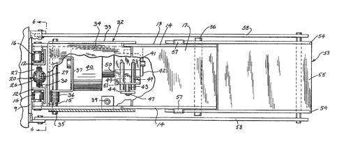
Fiq. 1 is a side elevation of the vehicle
restraint shown in the storage or inoperative position;
Fiq. 2 is a top plan view of the vehicle
restraint with parts broken away in section;
Fig. 3 is an enlarqed side elevation of the
vehicle restraint;
Fiq. 4 is a view similar to Fig. 3 and
showinq the vehicle restraint engaqed with the ICC har
on a truck;
' , .
1 Fig. 5 is a fraqmentary side elevation with
parts broken way showing the mechanism for releasing
the vehicle restraint from the ICC bar;
Fig. 6 is a section taken alonq line 6-6 of
Fiq. 2 and showing the biasinq mechanism for the slide;
Fi~. 7 is a vertical section of further form
of the vehicle restraint utilizinq a modified biasinq
mechanism; and
Fiq. 8 is a fragmentary vertical section of a
further form of the vehicle restraint utilizing a
modified release mechanism.
Description of the Illustrated Embodiment
~ . ~
The drawinqs illustrate a vehicle restraint 1
mounted on a loadinq dock 2 and adapted to engaqe an
ICC har 3 located at the rear end of truck 4 to prevent
the truck from accidentally pulling away from the load-
ing dock while a loading operation is in proqress.
The ICC bar 3 is a horizontal bar or beam
located at the rear of the truck beneath the truck bed
and acts to prevent an automobile from underriding the
truck in the event of a rear end collision. Delivery
and over the road trucks are required to have an ICC
har, althouqh the cross sectional confiquration may
vary and the height of the ICC bar above the qround may
also var~ within prescribed limits.
In most installations, loadinq dock 2 will
also include a pit or depression S and a dockboard 6 is
mounted within the pit. The dockboard may take the
form of that disclosed in U.S. Patent No. 4,488,325,
and in qeneral, includes a ramp 7 which is hinqed at
its rear edqe to the frame of the dockboard and is
movable between a generally horizontal cross traffic
position and an upwardly inclined postion. Pivoted to
the forward end of the ramp is a lip 8 which can be
moved between a downwardly hanging pendant position and
. , ' ' ~ .
.
,
1 an outwardly extended position where the lip ~or~s an
extension to the ramp and can engage the bed of the
truck 4. Dockboard 6 in itself forms no part of the
present invention and the vehicle restraint can be
mounted on loading docks that may or may not include a
dockboardO
Vehicle restraint 1 includes a mounting plate
9 which is secured to the front face of dock 2 throuqh
a series of conventional anchor bolts, not shown~ A
weldment 10 is secured to the upper end of mounting
plate 9 and includes an anqular plate 11 which serves
to guide the lower end of the pendant lip 8 of the
dockboard outwardly away from the mounting structure.
A pair of anqle shape guide tracks 12 are
mounted in spaced relation on mounting plate 9 and a
slide or carriage 13 is mounted for vertical sliding
movement in tracks 12. Carriage 13 includes a pair of
qenerally vertical spaced side plates 14 which are
connected at their inner ends by a cross plate 15.
Upper and lower roller 16 are journalled on the inner
ends of each side plate 14 and the rollers 16 are
adapted to ride in tracks 12 to facilitate vertical
movement of carriaqe 13.
An inclined plate 17 is secured to the upper
edqes of the outer portions of side plates 14, and
plate 17 extends downwardly and outwardly from the dock
at an anqle of about 40 to the horizontal. The upper
edqe of each side plate 14 is cut out to provide a
notch 18 and the outer end of each notch 18 is bordered
by a generally vertical shoulder 19.
Slide 13 is biased to an upper position with
respect to mountinq plate 9 by a gas sprinq assembly
20. As shown in Fig. 6, qas spring assembly 20
includes a cylinder 21 that contains a comPressed gas,
such as nitrogen, and a piston rod 22 extends outwardly
.~ ,. . ..
~8~6~
--7--
1 from the lower end of cylinder 21 and is threaded in a
nut 23 that is mounted on base plate 24 which projects
outwardly from the lower end of mountinq plate 9. The
upper end of gas cylinder 21 carries a clevis 25 and a
pulley 26 is journalled in clevis 25. As best shown in
Fig. 2, pulley 26 is adapted to move vertically in a
track or channel 27 that is bordered by the legs of
angles 12.
A cable 29 is trained over pulley 26 and one
end of cable 29 is secured to a luq 30 on slide 13.
which projects inwardly from cross plate 15, while the
opposite end of cable 29 is dead-ended at 31 on one the
angles 12.
With this construction, the force of the qas
sprinQ assembly 20 will tend to extend the piston rod
22 and urqe slide 13 to an upper position relative to '
mountinq plate 9. The use of the pulley 2~ and cahle
29 provides a 2:1 stroke of travel for slide 13 with
respect to the stroke of piston rod 22.
As a truck 4 backs toward loading dock 2, the
ICC bar 3 will enqaqe the inclined surface 17 on slide
13, thereby wedging the slide downwardly against the
force of the qas spring assembly 200 Continued move-
ment of the truck toward the loading dock will wedge
the slide 13 down to a position where the ICC bar will
fall into the notch 18 in the upper surface of the
slide to thereby lock the ICC bar and truck against
outward movement in a direction away from the loading
dock. Slide 13 thus constitutes a restraininq mem-
ber. If the truck attempts to pull away fro~ the dock,
while locked to the vehicIe restraint, the ICC bar 3
will engaqe the upstanding shoulder 19 to prevent out-
ward movement of the ICC bar and truck. With this
construction, the entire slide 13 and mountinq assembly
is used to restrain outward movement of the vehicle.
"
.
1 The stroke of the gas spring assembly 20 is
correlated with the travel of slide 13 so that the
force of the gas spring assembly or biasing mechanism
is not fully expended when the slide or restraining
member 13 is engaged with the ICC bar. Thus, the gas
spring assembly will enable the vehicle restraint to
follow both upward and downward float of the ICC bar
and truck bed during a loading operation.
The vehicle restraint includes a release
member 32 composed of a pair of spaced generally verti-
cal side plates 33 which are connected by a top plate
34. Release member 32 is pivotally connected to the
upper portion of slide 13 by a horizontal shaft 35, and
a torsion spring 36 is employed to bias the member 32
to an upper position, as shown in Fiqs. 1 and 3, where
the release member extends upwardly and outwardly from
dock 2. As shown in Figs. 2 and 3, torsion spring 36
includes a central section 37 which bears on the under-
side of top plate 34, while the ends 38 of the torsion
spring bear against the cross plate 15. Thus, the
force of torsion spring 36 will urge the release member
32 to the upper position.
As the truck 4 backs towarfl dock 2 and the
ICC bar 3 wedqes carriage 13 downwardly, the ICC bar
will fall into the notch 18 thereby pivotinq release
member 32 downwardly to a generally horizontal position
as shown in Fig. 4. When release member 32 is moved to
the horizontal position, it actuates a limit switch 39
which is mounted within slide 13 on one of the side
plates 14. Actuation of limit switch 39 will operate a
signal on loading dock 2 indicating to the operator
that the vehicle restraint is hitched with the ICC
bar. The siqnal may commonly take the form of a light-
ed sign which will indicate "hitched" when the release
bar is depressed and limit switch 39 is actuated.
1 After the loading operation has been com-
pleted, ICC bar 3 is released from the notch 18, as
shown in Fiqs. 1-5. The release mechanism includes a
motor 40 and a gear box 41 which are mounted on a
horizontal shelf 42 projectinq inwardly from one of the
side plates 14. The output shaft 43 of qear box 41
carries a qenerally rectangular crank plate 44. Pin 45
projects outwardly from crank plate 44 at a location
offset from shaft 43 and pin 45 is mounted for movement
in an elongated slot 46 formed in arm 47. The opposite
end of arm 47 is pivotally connected to a luq 48 which
depends from the outer end of release member 32. With
this construction, rotation of shaft 43 will corres-
pondingly rotate crank plate 44 to move arm 47 in a
vertical linear path. When the ICC bar 3 is engaged
with the notch 18, and release member 32 is depressed,
operation of motor 40 will cause an upward force to be
exerted throuqh arm 47 aqainst ICC bar 3, and as the
ICC bar cannot move upwardly, a reactive force is
exerted downwardly against slide 13 causinq the slide
to move downwardly as shown in Fiq. 5, aqainst the
force of the gas sprinq assembly 20, to thereby
disenqaqe the ICC bar from notch 18 and enable the
truck to pull away from the loading dock.
A pair of proximity sensors 49 are mounted on
bracket 50 which is carried on the upper surface of
qear box 41. Bracket 50 is provided with a horizontal
slot 51 which enables the sensors to be adjusted hori-
zontally, and adjustment of the bracket relative to the
gear box enables the proximity sensors to be adjusted
toward and away from crank plate 44. After the crank
plate is rotated throuqh 180 the sensors 49 will sense
the presence of the corners of the crank plate 44 to
stop operation of the motor 40.
--10--
1 In operation of the vehicle restraint, the
slide 13 is normally in an upper position due to the
biasinq affect of the gas spring assembly 20, and the
release member 32 is in its upper position with pin 45
being positioned in the upper end of slot 46.
As the truck 4 backs toward the loading dock
2, the ICC bar 3 enqaqes the inclined plate 17, wedginq
slide 13 downwardly aqainst the force of the gas sprinq
assembly 20. When the rear end of the truck engaqes
the bumpers 52, which are mounted in the front face of
the dock on either side of pit 5, the ICC bar will be
located above the notch 18. If the pin 45, is initi-
ally in the upper end of the slot 46, release member 32
will not be depressed by the ICC bar, but instead will
be held in the upper position by crank plate 44 and arm
47 This enables the truck to pull away from the dock
without being enqaqe~ by the vehicle restraint if the
truck is misaligned with the dock.
If the truck is properly aligned, the motor
40 is operated causing crank plate 44 to rotate and the
slide 13 will float upwardly through the force of the
qas spring assembly 20 to depress the release member 32
and enqaqe the ICC bar 3 with the notch 18. The force
of qas spring assembly 20 is greater than the force of
torsion sprinq 36. The ICC bar is thus locked to the
dock, preventinq the truck from pulling away from the
dock.
On the other hand, if the pin 45 initially is
in the lower end of the slot 46, movement of the ICC
bar over the peak of the inclined surface 17 will en-
able the biasing ~echanism to urqe the slide plate up,
depressinq the release member to enqaqe the ICC bar
with notch 1~.
When the loadinq operation has been completed
and it is desired to permit the truck to ~ull away from
. ~
~8~i~6~
1 the dock, motor 40 is actuated thereby rotating crank
plate 44 and causinq an upward force to be exerted
throuqh arm 47 aqainst the ICC bar. As the ICC bar 3
cannot move upwardly, a downward reactive force is
S created aqainst the slide 13 movinq the slide downward-
ly as shown in Fiq. 5 until the release member 32 is in
its upper position where the outer end of release mem-
ber 32 is adjacent the upper end of shoulder 19. As
the release member 32 is then locked aqainst downward
movement, the truck can pull away from the dock,
wedqing the release bar 32 and slide 13 downwardly as
the ICC bar 13 passes over the upper end or peak of the
plate 17.
The vehicle restraint on the invention also
includes a Provision for increasing the operatinq range
for a qiven vertical dimension of the slide or carriage
13. In this reqard an extension leq 53 is connected to
the forward end of slide 13. Leg 53 is qenerally U-
shaped in cross section and includes a pair of spaced
~0 side walls 5~ which are connected together by a top
wall 55. Leg 53 is pivotally connected to the side
plates 14 of carriaqe 13 by a shaft 56.
With the position of the pivot shaft 56, leq
53 will tend to pivot by qravity in a clockwise direc-
tion as shown in Fiq. 3. However, the clockwise
pivotal movement is limited by enqagement of the upper
ends of the side walls 54 with stops 57 that pro~ect
outwardly from side plates 14 of slide 13. With side
walls 54 enqaqed with stops 57, leq 53 provides an
extension to the inclined surface 17 of slide 13.
While the leq 53 is prevented from pivotinq
downwardly, it can freely pivot upwardly as slide 13
~oves downwardly. As shown in Fiq. 3, the lower end of
leg 53 is connected by a pair of arms or links 58 to
anqles 11 on mountinq plate 9. As slide 13 is wedged
.
-12-
downwardly by en~aqement with ICC har 3 to a predeter~
mined position, the connection of arms 58 to leq 53
will cause the leg to pivot upwardly, as shown in Fi~.
4, to prevent the leg from contacting the driveway 59.
If a truck has a low ICC bar 3 in the ranqe
of approximately 15 inches from the qround, the ICC
bar, as the truck backs toward the dock, will initially
engaqe lec1 53, wedging the leg 53 and slide 13 down-
wardly against the force of the gas spring assembly
20. As the truck continues to back toward the dock,
the ICC bar will ride against the incline plate 17 and
ultimately will be engaged with the notch 18, as pre-
viously described. However, as the slide 13 is
depressed, the outer end of leg 53 will pivot upwardly,
because of the connection of arms 58 to the mounting
plate 9, to prevent the outer end of leg 53 from con-
tacting the driveway. This construction substantially
increases the operating range of the vehicle restraint
for a qiven vertical ~3imension of slide and yet pre-
vents the extension lecl 53 and slide 13 from contactinq
the driveway 5~.
Fig. 7 illustrates a modified arran~ement of
the hiasinq rnechanism for the slide or carriaqe. In
this embodiment a slide 60, similar in construction to
slide 13, is ~ounted for vertical sliding movement on
quide tracks 12 of mountinq plate 9 and a yoke 61 is
mounted for horizontal sliding movement on a pair of
spaced guide tracks 62 secured to one of the side
plates 63 of slide 60. Gas sprinq assembly 64 is
located within carriage 60 and includes a cylinder 65
which is attached to a luq 66 projecting inwardly from
one of the side plates 63. Piston rod 67, which pro-
jects outwardly from the opposite end of cylinder 65,
is connected to yoke 61. The force of the gas in gas
spring assembly 64 will normally force yoke 61 outward-
ly away frorn dock 2.
' ' .
, ' . . ,
-13-
1 A cable 6~ is dead ended at 69 on slide 60,
then passes around a pulley 70 rotatably mGunted on the
outer end of yoke 61. Cable 68 then travels around a
pulley 71 journalled on side plate 63 and then around a
second pulley 72 rotatably mounted on the lower end of
yoke 61. Cable 68 then passes inwardly over a pulley
73 and is secured to a lu~ 74 on the fixed mountin~
frame. With this arrangement, the force of the qas
sprinq assemhly 64 will urge the carriaqe 60 upwardly
and the cable and pulley arran~ement will provide a
substantially ~reater stroke of movement for carriaqe
60 than the stroke of piston 66.
In the construction shown in Fig. 7, the
entire biasinq mechanism is located within slide 60 in
a location where it will not be sub~ect to imPaCt or
damage and will be protected from dirt, weather and the
elements.
For purposes of clarity, the operating
mechanism for operating release member 32 is not shown
in Fig. 7.
Fiq. 8 illustrate a modified form of the
mechanism for operating the release member or bar. As
shown in Fiq. 8, a slide or carriage 75 similar in
construction to slide 13, is mounted for slidinq move-
ment on the mountinq frame, and a release member 76,similar in construction to release member 32, is pivot-
ed to the inner end of slide 75 at pivot 77. As pre-
viously described, release member 76 is biased to an
upper position by a torsion sprinq 78.
To actuate release member 76, a toqgle
mechanism 79 inconnects the outer end of the release
bar 76 with slide 75. Toggle mechanism 79 includes a
link 80 which is pivoted to the outer end of release
bar 76 at pivot 81, while a second link 82 is pivotally
connected to the lower end of one of the side Plates 83
,
`
:
~2~
--14--
of slide 75 at pivot 84. The ar3jacent en~s of links 80
and 82 are connected together at a pivot 8 5.
Tog~le links 80 and 82 are movable between an
under center position as shown by the full lines in
Fiq. 8, and an over-center or locked position, as shown
by the phanto~ lines in Fiq. 8, through a push-pull rod
86 which is connected to the pivot pin 85. Rod 86 can
be operated manually by an operator standinq on loading
dock 2, or alternately, can be power operated or can be
tied in to movement of the ramp 7 or lip 8 of the dock-
board 6.
A pair of stops 87 and 88 are mounted on the
side plate 83 of slide 75 and limit the position of the
toggle links 80 and 82 in the under-cen'cer and over-
center positions.
When it is desired to release the ICC bar 3
from engagement with the notch 89 in slide 7 5, rod ~6
is pulled inwardly toward the dock 2, movincl the to~qle
links 80 and 82 from the under-center position 1:o the
over center position as shown by the phantom lines in
Fig. 8. This action will create an upward force
against ICC bar 3, and as ICC bar 3 cannot be moved
upwardly, a resultant downward force is created to move
slide 75 down a~lainst the force of the qas spring bias-
inq rnechanism. When the toggle mechanisTn reaches the
over-center position, it will be latched so that the
release bar 76 cannot be depressed, and thus outward
movement of the ICC bar as the truck pulls away will
wedc~e the release bar 76 and slide 75 downwardly
against the force of the gas sprinq biasinq mechanisrn
until the ICC bar 3 passes the peak of the slide.
While the drawings have illustrated the use
of a crank plate or toqgle linkaqe for moving the
release bar, it is contemplated that other mechanisms
such as a linear actuator or a hydraulic cylinder can
,
~2~
-15-
1 also be employed. Similarly~ biasinq mechanisms, other
than gas spering assemblies 20 and 64, can be used to
ur~e the slide or restraininq member to an upper
position.
- . :
'