Note: Descriptions are shown in the official language in which they were submitted.
~2~iZ~3
SHAPED THERMOFORMED FLEXIBLE FILM CONTAINER FOR
GRANULAR PRODUCTS AND METHOD A~D APPARATUS
FOR MAKING THE SAME
TECHNICAL FIELD
The present invention pertains to thermoformed
containers, and more particularly to thermoformed containers
for granular products wherein the container is made from
5 flexible film materials and shaped to assume a predetermined,
solid configuration having an aesthetically attractive
appearance. The present invention also pertains to a method
and apparatus for making such shaped, flexible film
containers .
BACKGROUND OF THE INVENTION
.
Therrnoformed vacuumed containers are well known
in the art of packaging rigid products such as hot dogs and
cheeses. The automatic packaging machines in commercial use
typically assemble such containers from two continuous webs
15 of plastic material that are supplied as rollstock. In such
machines, a lower web of rigid material is first thermoformed
into a series of cup-shaped lower containers, each cup having
a peripheral flange around its mouth. Thereafter, a rigid
product is placed within each cup before they are indexed to
?O an evacuation/sealing chamber. Inside the chamber, the cups
are evacuated, followed by heat sealing an upper web to the
peripheral flange surrounding each cup. The series of
heat-sealed cups are then removed from the evacuation/sealing
chamber for further processing, which typically includes
25 cutting or stamping the series of cups into individual
packages ready to be placed inside shipping cartons.
In order to achieve material cost savings, some
thermoform/vacuur- processes utilize webs of 'lexible material
in packaging rigld products. When such flexible film
30 packages are evacuated, sealed, and removed from the
sealing/evacuation charaber, the pressure differential between
~` ~2~1~2~
inside and outside the package causes t'ne flexible film to
shrivel into close contacting relation with the product therein.
Since the product is rigid and has a relatively constant
shape, the package's final shape is the same as the product
5 itself, which typically is an easy to handle shape such as
square or rectangular. Therefore, using flexible films in
vacuum packing rigid products is a relatively simple matter.
Special care must be taken when granular or
flowable products are vacuum packed within thermoformed
10 containers. As pointed out in U.S. Patent No. 4,424,659,
which issued to Perigo et al. and is hereby incorporated
herein by reference, it is necessary to leave a ~Iheadspace~
between the surface level of the flowable product and the
heat-sealing surface of the cup's peripheral flange in order to
15 avoid contaminating this surface or otherwise causing
interference between the upper web and the sealing surface
during the heat-sealing operation. The headspace is
particularly necessary when vacuum packaging a light
granular product such as ground coffee because turbulence
20 created during the èvacuation step can draw granules out of
the cup and deposit them on the cup's flange.
In order to achieve substantial material cost savings
over the shape retaining, thermoformed containers of the type
generally disclosed in Perigo, the present invention utilizes
25 thin, non-shape retaining or flexible films in vacuum packing
granular products. However, it has been found that using
flexible film material for the lower cup presents several
troublesome problems. Specifically, when such a flexible film
container filled with a granular product is removed from the
30 sealingtevacuation chamber, atmospheric pressure outside the
container shrivels the lower cup and pushes the product up
into the headspace. Since the product does not have a shape
of its own, the resultant package assumes a random shape
that is very difficult to handle during subsequent processing
35 operations. In addition, such a shrivelled, randomly-shaped
-` 1286258
package has an outer appearance that looks something
like a prune. It has been found that most consumers
find such a package unattractive. Finally, the
randomly-shaped and shrivelled film often includes sharp
ridges and valleys that are prone to scuffing and
abrasion during subsequent handling operations. If the
scuffing or abrasions are excessive, the film might
develop small holes which would allow oxygen to enter
the package and product to escape.
In light of the above, an object of an aspect of
the present invention is to achieve significant material
cost savings in vacuum packaging a granular product in a
thermoformed container by making the container's lower
cup from flexible, non-shape retaining films.
An object of an aspect of the present invention is
to provide a thermoformed, flexible film, vacuumed
container having a granular product therein with a
predetermined, constant shape.
A principal object of an aspect of the present
invention is to provide a thermoformed, flexible film,
vacuumed container having a granular product therein
with an aesthetically pleasing appearance.
An object of an aspect of the present invention is
to provide a thermoformed, flexible film, vacuumed
container that exhibits a reduced amount of wrinkling
and a corresponding higher degree of abrasion
resistance.
An object of an aspect of the present invention is
to provide a thermoformed, flexible film, vacuumed
container that is solid, relatively easy to open, and
exhibits good oxygen and moisture barrier properties.
An object of an aspect of the present invention is
to provide an economical manufacturing method of making
reshaped, vacuumed, flexible film packages for granular
products.
., ~
-` i286~5~3
An object of an aspect of the present invention is
to provide efficient apparatus for making reshaped,
vacuumed, flexible film packages for granular product.
SUMMARY OF THE INVENTION
The present invention provides an economical,
thermoformed container for granular products that is
made from two webs or films of flexible material.
According to one embodiment of the present invention, a
web of flexible film material is thermoformed into a
series of cup-shaped containers, each cup having a
peripheral ~lange around the cup's mouth. The cups are
then partially filled with a granular product such that
there is a headspace between the product's top surface
and the cup's peripheral flange. The cups are then
placed in a vacuum/sealing/shaping chamber wherein
substantially all the air inside the cups is removed,
followed by sealing an upper web of flexible film
material to each cup's peripheral flange. ~efore the
sealed containers are removed from the
vacuum/sealing/shaping chamber, a shaping die located in
the bottom of the chamber is thrust upwardly into each
cup's bottom wall. The shaping die forces the granular
product up into the headspace and pushes the cup's
excess film material upwardly, thereby forming a concave
impression or dome in the cup's bottom wall. The
chamber is then returned to atmospheric pressure before
the containers are removed. Atmospheric pressure holds
the containers in this pre-selected solid shape, which
is not only easy to handle in subsequent operations, but
also exhibits a substantially reduced amount of
wrinkling that is much more aesthetically pleasing than
if the containers were not given a preselected shape.
The reduced wrinkling also improves scuff and abrasion
resistance.
-` ~2~36~5~3
4a
The present invention also provides apparatus for
making thermoformed, vacuumed, shaped, flexible film
containers of the present invention.
According to another aspect of this invention
there is provided
A sealed, thermoformed container comprised of non-
shape retaining flexible film, but exhibiting a
preselected, substantially solid shape, said container
having a granular product therein and being
substantially free of gases, said container comprising:
(a) a lower cup defining a hollow cavity of
preselected size and shape thermoformed from a
non-shape retaining flexible film, said lower
cup having an upper peripheral flange and a
bottom wall, said bottom wall being provided
with a concave impression also of preselected
size and shape extending into said hollow
cavity at a preselected location;
(b) a predetermined quantity of said granular
product contained within said hollow cavity
and having a top surface in the form of a
composite of the uppermost granules of said
product; and
(c) a substantially planar top lid having a distal
edge and a bottom surface, said distal edge
being continuously and releasable sealed about
said upper peripheral flange of said lower
cup, said bottom surface of said substantially
planar lid being incontinuous contacting
relation with said top surface of said
predetermined quantity of granular product,
whereby atmospheric pressure acting upon the
exterior surfaces of said sealed,
substantially gas-free container maintains
3~ said container in said preselected,
substantially solid shape until said container
is opened.
lX~3~2S~3
4b
A method of making a sealed, thermoformed container
of preselected, substantially solid shape from a non-
shape retaining flexible film, said container having a
granular product therein and being substantially free
of gases, said method comprising the steps of:
(a) thermoforming a ].ower cup from a non-shape
retaining flexible film, said lower cup
defining a hollow cavity and having an upper
peripheral flange. and a bottom wall;
(b) filling said hollow cavity of said
thermoformed lower cup with a predetermined
quantity of said granular product, said
granular product having a top surface in the
form of a composite of the uppermost granules
of said product, said top surface being below
said upper peripheral flange of said lower
cup;
(c) substantially removing gases from inside said
hollow cavity of said lower cup by subjecting
said hollow cavity of said lower cup to
vacuum;
(d) continuously sealing the distal edge of a
substantially planar top lid having a bottom
surface about said upper peripheral flange of
said lower cup while said top lid, said hollow
cavity and said lower cup are subjected to
vacuum to form a sealed, substantially gas-
free container;
(e) mechanically deforming said bottom wall of
said lower cup into a concave impression of
preselected size and shape extending into said
hollow cavity of said lower cup at a
preselected location, yet maintaining said top
lid in a substantially planar condition while
said sealed, substantially gas-free container
is subjected to vacuum, thereby moving said
top surface of said granular product into
,
.
",,,,, ~
.. . ..
~8625~3
4c
continuous contacting relation with said
bottom surface of said substantially planar
top lid; and
(f) exposing said sealed, substantially qas-free
container to atmospheric pressure, thereby
causing said container to maintain said
preselected, substantially solid shape until
it ~s opened.
An apparatus for making a sealed, thermoformed
container of preselected, substantially solid shape from
a non-shape retaining flex:ible film, said container
having a granular product therein and being
substantially free of gases, said apparatus comprising:
(a) means for thermoforming a lower cup from a
non-shape retaining flexible film, said lower
cup defining a hollow cavity and having a
peripheral flange and a bottom wall;
(b) means for filling said hollow cavity of said
thermoformed lower cup with a predetermined
quantity of said granular product, said
granular product having a top surface in the
form of a composite of the uppermost granules
of said product, said top surface being below
said peripheral flange of said lower cup;
(c) means for subjecting said hollow cavity of
said lower cup to vacuum to substantially
remove gases from inside said hollow cavity of
said lower cup;
(d) means for sealing the distal edge of a top lid
having a planar bottom surface about said
upper peripheral flange of said lower cup
while said top lid, said hollow cavity and
said lower cup are subjected to vacuum to form
a sealed, substantially gas-free container;
(e) means for mechanically deforming said bottom
wall of said lower cup into a concave
impression of preselected size and shape
- ~28~25~
4d
extending into said hollow cavity of said lower cup
at a preselected location, yet maintaining said top
lid in a substantially planar condition while said
sealed, substantially gas-free container is
subjected to vacuum, thereby moving said top
surface of said granular product into continuous
contacting relation with said bottom surface of
said substantially planar top lid; and
(f) means for exposing said sealed substantially
gas-free containe!r to atmospheric pressure,
thereby causing said container to maintain
said preselected, substantially solid shape
until it is opened.
A method of making a sealed, thermoformed container
of preselected, substantially solid shape from a non-
shape retaining flexible film, said container having a
granular product therein and being substantially free of
gases, said method comprising the steps of:
(a) thermoforming a lower cup from a non-shape
retaining flexible film, said lower cup
defining a hollow cavity and having an upper
peripheral flange and a bottom wall;
(b) filling said hollow cavity of said
thermoformed lower cup with a predetermined
quantity of said granular product, said
granular product having a top surface in the
form of a composite of the uppermost granules
of said product, said top surface being below
said upper peripheral flange of said lower
cup;
(c) substantially removing gases from inside said
hollow cavity of said lower cup by subjecting
` said hollow cavity of said lower cup to
vacuum;
(d) continuously sealing the distal edge of a
substantially planar top lid having a bottom
surface about said upper peripheral flange of
."
-" lZ~36258
4e
said lower cup while said top lid, said hollow
cavity and said lower cup are subjected to
vacuum to form a sealed, substantially gas-
free container;
(e) exposing said sealed, substantially gas-free
container to atmospheric pressure;
(f) resubjecting saicl sealed, substantially gas-
free container to vacuum;
(g) mechanically de~orming said bottom wall of
said lower cup iIltO a concave impression of
preselected size and shape extending into said
hollow cavity of said lower cup at a
preselected location, yet maintaining said top
lid in a substantially planar condition while
said sealed, substantially gas-free container
is subjected to vacuum, thereby moving said
top surface of said granular product into
continuous contacting relation with said
bottom surface of said substantially planar
top lid; and
(h) exposing said sealed, substantially gas-free
container to atmospheric pressure, thereby
causing said container to maintain said
preselected, substantially solid shape until
it is opened.
~8~i258
BRIEF DESCRIPTION OF THE DRAWINGS
- While the specification concludes with claims
particularly pointing out and distinctly claiming the subject
matter regarded as forming the present invention, it is
5 believed that the invention will be better understood from the
following description and dravYings in which:
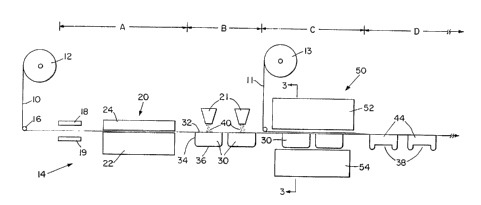
Figure 1 is a schernatic side view of an apparatus
for making thermoformed, vacuumed, shaped, flexible film
containers for packaging granular products;
Figure 2 is a side view of a thermoformed,
vacuumed, flexible film container having a granular product
therein that has not been shaped into a predetermined
configuration according to the present invention;
Figures 3-6 are cross-sectional schematic views
1~ taken along section I ine 3-3 of Figure 1, each Figure
illustrating various steps that are performed in making
thermoformed, vacuumed, shaped containers of the present
invention;
Figure 7 is a bottom view of a thermoformed,
20 vacuumed, shaped container of the present invention.
DETAILED ~ESCRIPTION OF THE INVENTION
.
In the following detailed description of the present
invention, the same numeral is used to indicate common
apparatus and vorkpiece components fnund in each
2~ illustration. In addition, the terms "web" ard "film" are used
synonymously throughout. Finally, the frame, transport
means, vacuum sources, and means for moving the various
apparatus components and the like which must necessarily be
provided with respect to the functional members of the
30 disc!osed apparatus are not shown in the figures or described
in detail in order ~o simplify and more clearly disclose the
present invention, it being understood that such details are
well within the kno~vle~ge of those skilled in the art of
making thermoformed filledlvacuumed/sealed containers.
~ ~862S~
Figure 1 is a schematic side view of a particularly
preferred apparatus that is utilized in making
thermoformed/filled/vacuumed/sealed/shaped containers of the
present invention. In Figure 1, a lower web or film of
material 10, supplied from rollstock 12, is fed into the
apparatus generally indicated as 14 from left to right. From
rollstock 12, film 10 is drawn first downwardly to guide roller
16, then horizontally indexed through successive zones A, B,
C and D of apparatus 14. ~one A is the thermoforming
component of apparatus 14 wherein film 10 is first heated
above its softening temperature by upper and/or lower
heating elements 18 and 19, then drawn into a thermoformer
generally indicated as 20 and preferably comprising lower
chamber 22 and top plate 24. The interior portion of lower
chamber 22 defines a mold cavity of a shape corresponding to
that required for the bottom wall and side walls of the lower
cups to be formed. As illustrated, thermoformer 20
simultaneously forms a 2x2 block of lower cups, although any
convenient number and arrangement of cups may be selected.
Briefly, after the heated and softened film 10 is
indexed into thermoformer 20, top plate 24 is lowered into
sealing engagement with lower chamber 22 as shown. After
plate 24 and chamber 22 are closed, a pressure differential is
created on opposite sides of film 10 whereby film 10 is drawn
and stretched into contacting relation with the interior side
walls and bottom wall of lower chamber 22 to form a plurality
of cup-shaped containers 30 (hereinafter "cups"), each cup
having a peripheral flange 32 around its mouth or charging
opening. Alternatively or in addition, a plug assist member
(not shown) having a shape which substantially coincides with
the cavities in lower chamber 22 rnay be provided in the area
of top plate 24 and can be used to mechanically form cups 30.
In still another embodiment, top plate 24 could be eliminated
altogether. In the latter case the cups can be formed by
establishing a seal between film 10 and the uppermost surface
of lower chamber 22 and applying a vacuum to the interior
portion of the lower chamber. In drawing and stretching film
10, side walls 34 and bottom end wall 36 of cups 30 become
62S8
thin and flexible. As used herein, the term l'flexiblel' means
incapable of maintaining a fixed shape by itself, i . e.
non-shape retaining. By making cups 30 thin and flexible,
substantial material cost savings over other prior art rigid
thermoformed containers can be realized,
After cups 30 have cooled, thermoformer 20 is
opened and cups 30 are indexed to zone B of apparatus 14.
In zone B, charging hoppers 21 fill each cup 30, preferably
by gravity, with a pre-selected quantity of a granular
product 40 to a level below the upper peripheral flange 32 of
cup 30, thereby leaving a headspace. In charging cups 30,
it is not practical nor desirable to completely fill each cup
because overcharging runs the risk of contaminating the cupls
sealing surface, which is upper peripheral flange 32, during
the sealing operation described hereinafter.
After cups 30 are charged with a predetermined
quantity of a granular product 40, the cups are indexed to
zone C of apparatus 14, which comprises a vacuum/sealing/
shaping chamber ~hereinafter l'VSS chamber") generally
indicated as 50, the function of which will be described
hereinafter in detail with reference to Figures 3-6. Briefly,
after filled cups 30 are indexed into VSS chamber 50, upper
sealing die 52 and lower sealing die 54 are closed in sealing
engagernent around cups 30. Thereafter, air is evacuated
from within VSS chamber 50, followed by sealing an upper
film 11 fed into VSS chamber 50 from rollstock 13 to the
peripheral flange 32 of each cup 30. Before VSS chamber 50
is returned to atmospheric pressure, a moveable shaping die
located in the bottom of lower sealing die 54 is rammed into
the bottom wall 36 of cup 30. The upward movement of the
shaping die redistributes the granular product inside cup 30
up into the headspace and makes a concave impression or
dome 38 in bottom wall 36 of cup 30, thereby taking up the
excess film material. The shaping die is held in its upward
position until VSS chamber is returned to atmospheric
pressure. After VSS chamber 50 is returned to atmospheric
pressure, upper sealing die 52 and lower sealing die S4 are
separated, followed by indexing finished containers 44 into
-` ~Z86Z5~3
zone D. In zone D, the series of sealed, shaped containers
44 are severed from the continuous web and placed in cartons
for shipping.
When VSS chamber 50 is returned to atmospheric
pressure and opened as described above, it is particularly
significant that the pressure differential between the interior
and exterior of container 44 holds the container in the fixed
shape given to it by the forming die. Of further significance
is that the pressure differential helps hold top film 11 to
10 peripheral flange 32 of cup 30, which makes it possible to
make a weaker seal between the two than would otherwise be
the case, which in turn makes it easy for a consumer to peel
top film 11 away from container 44 when the container is
opened .
Figure 2 is a side view of what container 44 would
look like if it were evacuated and sealed but not shaped as
described above. In Figure 2, the pressure differential
between the inside and outside of container 46 has caused
lower cup 30 to shrivel into a random shape. It has been
found that such a randomly-shaped container is extremely
difficult to handle in subsequent operations such as packaging
individual containers into a shipping carton. In addition, the
severe wrinkling exhibited on the outer surface of lower cup
30 gives container 46 an unattractive appearance that looks
something like a prune. Furthermore, the sharp peaks
resulting from such severe wrinkling provide scuffing and
abrasion concentration areas during subsequent handling and
shipping operations. In rough environments such as a long
distance shipment, the sharp wrinkle peaks can be subjected
30 to enough abrasion to cause holes develop in the film which
will allow air to enter the container and product to escape.
The following is a more detailed description of the
operational steps performed inside VSS chamber 50 in making
shaped flexible film containers of the present invention.
Figures 3-6 are cross-sectional schematic views of VSS
chamber 50 taken along section line 3-3 of Figure 1 (machine
direction). In Figure 3, a 2 x 2 configuration of
thermoformed filled cups 30 and a continuous web or film 11
of flexible material are indexecl within VSS chamber 50. VSS
chamber 50 comprises upper sealing die 52 and lower sealing
die 54 having a continuously interconnected rigid sidewall 55
defining a pair of adjacent cavities to provide firm support
for cups 30 when they are sinaped therein. VSS chamber 50
also comprises a sealing plate 60 and upwardly-moveable
10 shaping dies 64 attached to shafts 66. As shown, cups 30
are only partially filled with a granular product 40, thereby
leaving a headspace 41 between the top surface 42 of granular
product 40 and the upper peripheral flange 32 of cups 30.
Referring now to Figure 4, after cups 30 have been
15 indexed into VSS chamber 50, upper sealing die 52 and lower
sealing die 54 are closed together in sealing arrangement
around cups 30 with peripheral flange 32 of cups 30 providing
a seal at their interface. After VSS chamber 50 is closed, air
is evacuated from the interior portion of VSS chamber 50 by
20 using a vacuum pump lnot shown) connected to vacuum
passageway 56 of upper sealing die 52, and vacuum
passageway 58 connected to lower sealing die 54.
Referring now to Figure 5, after VSS chamber 50
has been evacuatèd, sealing plate 60 is lowered such that it
25 brings upper film 11 into contact with peripheral flange 32
surrounding each cup 30. Sealing plate 60 can either use
heat or ultrasonics to create seals between upper film 11 and
flange 32. If sealing plate 60 uses heat, it preferably has
areas 61 that are heated to a temperature sufficient to create
30 a heat seal between upper film 11 and the peripheral flange
32 of cup 30. Areas 61 ' of sealing plate 60 are preferably
maintained at a temperature below the softening temperature
of the filrn so that product granules will not adhere to areas
of upper film 11 corresponding to zones 61 ' . Such a
8~;2~3
preferred sealing plate 60 might use metal in areas 61 and an
insulating material such as silicone rubber for areas 61 ' .
After sealing plate 60 has formed a heat or ultrasonic
seal between upper film 11 and peripheral flange 32 of cup
5 30, shaping dies 64 located at the bottom of lower sealing die
54 are thrust upwardly into the bottom wall 36 of cup 30 by
means of shafts 66 and actuating means (not shown) such as
a rotating cam. The upward movement of shaping dies 64
forces bottom end wall 36 of cup 30 upwardly into a concave
10 impression or dome 38 such that granular product 40 is
redistributed and fills headspace 41, whereby the upper
surface 42 of product 40 comes into continuous contacting
relation with upper film 11. While shaping dies 64 are held in
the upward position illustrated in Figure 5, atmospheric
15 pressure is returned inside VSS chamber 50 through
passageways 56 and 58. Since the interior cavity of finished
containers 44 is substantially below atmospheric, the pressure
differential holds containers 44 in the shape provided by
shaping dies 64. Such a shape is not only aesthetically
20 attractive, but hydraulicaliy solid and easy to handle.
Furthermore, since shaping dies 64 have forced the excess
film material up into bottom end wall 36, finished containers
44 will exhibit substantially less film wrinkling than containers
46 illustrated in Figure 2. Less film ~f rinkling not only
25 results in a more attractive container, but one which is much
less susceptible to localized wearing and pin-holing when the
container is subjected to scuffing and abrasion during
subsequent handling operations.
Referring now to Figure 6, after atmospheric
30 pressure is returned inside VSS chamber ;0, upper sealing
die 52 and lower sealing die 54 are opened, followed by
indexing finished containers 44 into zone D of apparatus 14
where containers 4~ are severed from one another and packed
in shipping cartons. VSS chamber ;0 is now ready to receive
` --` i2~36258
11
another series of filled cups and repeat the evacuating,
sealing, and shaping process described above.
Figure 7 illustrates a bottom view of particularly
preferred thermoformed, flexible film container of the present
5 invention. In Figure 7, container 80 has a pentagon-shaped,
concave impression or dome 82 stamped in its bottom end wal 1.
Of course, shaping dies 64 and the other components of VSS
chamber 50 must have complementary configurations to give
such a shape to container 80. Distal edge 84 represents the
10area where top film 11 and peripheral flange 32 of cup 30 are
sealed together. Area 86 is preferably not sealed, which
provides a convenient place for a consumer to grasp that
corresponding free corner of upper film 11 ltop lid) and peel
it away from lower cup 30 to open container 80.
15As will be appreciated by those skilled in the art, a
wide variety of films which satisfy the definition of "flexible"
can be utilized in practicing the present invention. For
- example only, it has been found that a good film for lower
cup 30 is a 10-15 mil laminate comprising low density
20 polyethylene/saran/low density polyethylene. Another good
film that can be utilized is a 7 mil laminate comprised of
nylon/ethylene vinyl alcohol/linear low density polyethylene.
Suitable films for upper film 11 include a 4.5 mil laminate
comprised of polyester/saran/linear low density polyethylene/
25 EVA sealant, as well as a 2.25 mil laminate comprised of
polyester/saran/high density polyethylene/surlyn. Such films
provide attractive features such as strength, scuff
resistance, oxygen barrier, and moisture barrier.
Apparatus for and a method of making a novel and
30 economical thermoformed container for granular products are
thus provided. The apparatus shown has been somewhat
simplified so that a person skilled in the art of
thermoform/vacuum packaging may readily understand the
preceding description and readily incorporate the present
35 invention in a high-speed manufacturing environment by
~.2862~8
12
making a number of minor modifications and additions thereto,
none of which entails a departure from the spirit and scope of
the present invention. Accordingly, the following claims are
intended to embrace such modifications.
s