Note: Descriptions are shown in the official language in which they were submitted.
~2~6~(~3
Method of measuring the refractive-index profile
of optical fibers
This invention generally relates to a method for testing
optical fibers, and particularly to a method for determining
the refractive index profile of optical fibers of the type
used as telecommunication llghtguides.
Optical fibers are generally constructed with a glass
cylindrical core encased within one or more layers of cladding,
and light pulses are transmitted through the core of the
optical fiber. The light rays or modes of a pulse, typically
from a laser diode or light emitting diode, follow different
paths within the optical fiber core as they reflect back and
forth along -the boundary of the core and cladding. Since the
pulse length has a tendency to elongate during travel along
-the core and thereby restrain the bandwidth, optical fibers
have been manufactured with their core having an index of
refraction profile that varies radially from the axis of the
core to the periphery to facilitate telecommunication
applications. The refractive index distribution within the
optical fiber core should be designed so as to cause all
light rays of a pulse to travel along the optical fiber at
the same axial velocity regardless of variations in the
length of the path traversed. In practice, optical fiber
manufacturing processes introduce some deviation from
optimum refractive index distribution of the optical
fiber core. Therefore, the variation from an optimal
refractive index distribution must be consistently
,.~ i~
' ~. , , ',, ~ "' - ' ' '
" ' ' - ; ~ ' ', ', .
' ,'',
- , ~
, : . ~, ,, :' .
.
~2~6~03
-2-
monitored to ensure that the variation remains within
certain predetermined acceptable limits.
A numbee of methods have been developed and are
known for analyzing the refractive index profile of
optical fibers A good review of the various optical
fiber and preform index-profiling methods are disclosed
in an article by W. J. Stewart titled "optical Fiber
and Preform Profiling Technology~ EE Transactions
on Microwave Theory and Techniques, Vol. MTT-30, No. 10
(October, 1982). Perhaps the most widely accepted method
in use today is the refracted near-field method described
in the previously noted article. With this particular
method a lens having a numerical aperture substantially
larger than that of the fiber focuses a beam of light on
i5 a flat endface of a fiber and scans tl~e focused spot
across the fiber diameter. Part of the light is guided
down the fiber while the rest is refracted through an end
portion of the fiber and radiates as a hollow cone out-
side of the fiber. A shield or disc is placed in the
radiated cone to prevent the leaky modes in addition to
the purely reflected modes~from reaching a photodetector
which is positioned beyond the disc. A detail'ed review of
this method ïs set fort'n in an article titled ~Practical
Application of the Refracted Near-Field Technique for the
Measu~nt' of Optical Fiber Refractive Index Profiles~ by
K. I. White which was published in the March, 1979 issue
of Optical and Quantum Electronics
However, the refracted near-field technique suffers
from the practical problem of requiring highly sophisti-
cated optical equipment and thereby cenders obtainingrefractive index profiles a complex and expensive tas~.
The improved method of the present invention is directed
to obviating the requirement for sophisticated optical
equipment or complex procedures in order to obtain
accurate refractive index profiles o~ optical fibers.
.: , i
. ~
,
- .
1;2~364~3
In accordance with the present invention, a method
is peovided for deterrnining the refractive index pro~ile
of an optical fiber which does not require sophisticated
optical equipment or complicated measurement techniques.
The method comprises directing light from an intense op-
tical source at the uncoated end portion of an optical
fiber, most suitably at the interface of the bare fiber
and the coating, in such a fashion that only cladding
modes will be excited along the length of the uncoated
fiber and the excitation of the cladding modes is uni-
form. The light emerging ~rom the bare test end of the
optical fiber is directed through a lens system which has
a selected limited numerical aperture and into a vidicon
camera and electrically connected computer. The refrac-
tive index profile is then computed Erom the measured
intensity distribution of the light emerging from the
test end of the optical fiber.
Therefore, it is an important object of the present
invention to provide a method for obtaining the refrac-
tive index profile of an optical fiber using relatively
simple and unsophisticated optical equipment.
Uore specifically, an object of the present
invention is to provide a method for measuring the
refractive index of single mode or multimode optical
fibers which does not require sophisticated optical
equipment or complex procedures.
Still a further object of the present invention
is to provide a method for measuring the refractive
index profile of an optical fiber by exciting only
cladding modes within the fiber and analyzing the
intensity distribution of light emitted rom the test
fiber with a lens systems whose numerical aperture is
limited.
- ~ , ': - ' .'; '.. ' '
6~03
The pcesent invention will now be desccibed in
detail with refecence to the accompanying drawings in
which:
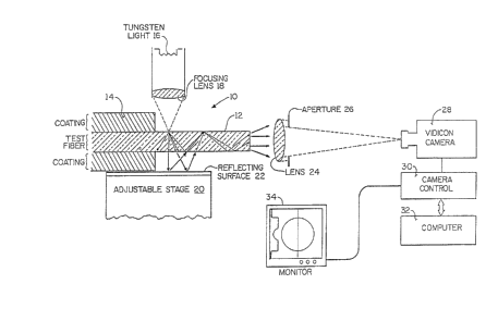
Figure 1 is a schematic diagcam of a system for
measuring the index of re~raction proEile of an optical
fibec utilizing the method of the present invention;
Figure 2 is a vertical cross-section view of an
optical fiber illustcating propagation of a cladding mode
thcough an optical fiber in accordance with the pcesent
invention.
Figure 3 is a vertical cross-section diagram of an
optical fiber illustrating cladding mode propagation used
for calibration;
Figure 4 is a graphic illustcation of a typical
calibration curve; and
Figure 5 is a graphical representation of a typical
intensity distribution curve and the coccesponding ce-
fractive index profile obtained using the method of the
present invention.
, . .
ReEerring now in more detail to the drawings, there
is schematically shown in Figure 1 an apparatus fcr measur-
ing the re~ractive index profile of an optical fiber 10
comprising bare fiber 12 and coating 14. ~ace fiber 12
can be seen with reference to Figures 2 and 3 as furthec
compcising an inner coce cegion 11 surrounded by an outer
cladding 13. The term ~optical fibec~ has been used to
indicate both single mode and multimode optical fibers.
A tungsten light 16 and focusing lens 13 are used to
dicect light towacd the intecface of uncoated optical
eiber 12 and coating 1~. It should be appreciated that
uncoated optical ~iber 12 is surrounded by air or any
o~
suitahle material whose reEractive index is less than
the refractive index of cladding 13. With this celative
positioning of tungsten light 16 and optical fiber 10 a
small fraction of the light power will be coupled into
cladding 13 where for the short length of uncoated opti-
cal fiber 12 only cladding modes will be excited. Optical
fiber 10 is positioned on micro-adjustable fiber stage 20
and reflecting material 22 is provided therebetween to
enhance the uniformity of the cladding modes excited by
tungsten light 16.
The light coupled into bare optical fiber 12 is
emitted from the end of the fiber and projected through
lens 24 and aperture 26 into vidicon camera 28. Aperture
26 is variable and most suitably placed directly behind
lens 24 so as to limit the numerical aperture of the light
measurement system. Vidicon camera 28 is electrically
connected to camera control 30 and computer 32, and is
additionally provided with video monitor 34. Computer 32
is most suitably programmed with software which converts
the emitted light intensity distribution from uncoated
optical fiber 12 directly into the refractive index
profile of the fiber.
In practice, thè cladding mode near-field method
of the invention is practiced by removing coating 1~ from
the end of a short portion of optical fiber 10 and pre-
paring the endface for testing according to conventional
procedures. The uncoated optical fiber 12 is surrounded
with a material such as air whose refractive index is
less than the refractive index of cladding 13. The light
from tungsten light 16 will excite only cladding modes in
optical fiber 12 which will propagate along the uncoated
fiber length as best seen in Figure 2. Utilizing Snell's
law, light ray trajectories at the output end of optical
fiber 10 can be described by:
~: .
.
.: .
~364~3
No cos ~l = N(c) cos ~2 (1)
N(r) si.n ~2 = sin ~3 (2)
where N(r) is t~le local refcactive index alon~ t~le
exit plane of Eiber 10 and No is the refractive index of
cladding 13. The angle of incidence ~I can be uniquely
related to the cocresponding exit angle ~3 by combining
equations 1 and 2 from above as follows:
N(r.)2 - No2 = - No2 sin2 9~ + sin2 33 (3)
It is apparent from equation thcee that the magnitude of
N(r) at any radial position along the endface of o~tical
fiber 10 determines the relationship between a~ and ~3.
Therefore, if No and sin ~3 are fixed, a change in N(r)
will induce an equivalent change in sin ~I.
The emitted intensity distribution from the end-
lS face of optical fiber 10 is measured by vidicon camera 28
whose numerical aperture is limited (fixed at sin ~3max)
by placement of a selected optimum aperture 26 behind
lens 24 so that the total power at any arbitrary point
along the detected pattern is directly related to ~Imax
(the power due to the total number of cladding modes pro-
pagating with an angle of incidence less than or equal to
max). Since the relationship between a, and intensity
can be determined prior to conducting refractive index
profile measurements by a technique to be described here-
a.Eter, then merely by utilizing equation 3, N(r) valuescan be determined directly ~rorn t~le measured intensity
distribution by computer 32. It should be again observed
that uniformity of cladding mode excitation by tungsten
light 16 is required in order for tile above relationship
to be valid. This is Eacilitate~ by the orientation of
tungsten light 16 and Eocusing lens 18 so as to direct
light genecally perpendicularly to the longtitudinal axis
of optical fiber lO. ltoreover, micro-adjustable fiber
stage 20 assists in propec ali~nment of optical fiber 10
~: .
- :: ~ : .
.
. ' :
,
~2~ 03
relative to tungsterl light 16, and re~lecting material
22 serves to reflect the light to enhance the uniform
launch condition.
Therefore, if uniform cladding mode excitation exists
the refractive index profile of optical fiber 10 can be
detecmined by analyzing the emitted intensity distribu-
tion. However, for each optical fiber which is analyzed
by the cladding near-field method of the present inven-
tion, the relationship between intensity and 3~ tthe
variable used to calculate the index of refraction) must
be determined prior to beginning the measurement by a
calibration procedure. Since this relationship may be
slightly different for different optical fibers, the
calibration procedure should be conducted before each
individual fiber eefractive index profile measurement.
With reference now to Figures 3 and 4, applicant will
describe the basic principle for the calibration step
used to determine the relationship between intensity and
~. Applying Snell's law to cladding area 13 only (see
Figure 3), light exiting this area can be described by
the following equation which is equation three simplified
for the cladding region:
~l = sin ~ (l/No sin ~3 ) (4)
where ~l is t~le cladding mode propagation angle of
incidence, ~3 is the angle at which light exits cladding
area 13, and No is the reeractive index of cladding 13
and is a constant value. Placing a variable aperture 26
or several dif~erent apertures 26 between optical fiber
10 and vidicon camera 2~3 enables the numerical aperture
or light acceptance ability of the light detection system
to be adjusted Since the numerical aperture is sin ~3,
the relationship between ~ and intensity may be easily
obtained from the equation by measuring the intensity
along cladding 13 foc several, most suitably four, dif~
ferent size apertures 26. Fitting this information
.
- '' , -
. ' , ~ ' ' : ; '
~21~6~ 3
~3--
to a least squaees ~echnique provides Eoe plottin~ acalibcation curve such as the cepcesentative cucve shown
in Fi~ure 4. Then a selected apertuce (for best spatial
resolution and within the signal to noise ratio oE the
detector) is used to obtain an intensity pro~ile Eor
fiber 10. Using the previously developed calibration
curve to determined ~I values corresponding to the in-
tensity values, the necessary al values are developed to
facilitate computation o~ the refractive index of fiber
10 from equation three by computer 32.
~ aving explained the theory supporting the method
of the present invention, the preferred procedure for
calibcation and measurement may be very simply set forth.
First of all, the endface of optical fiber i0 is prepared
for testing accordin~ to standard procedures. Optical
fiber 10 is inserted into stage ~0 and adjusted until
maximum alignment is obtaine~. The intensity profile is
observed on monitor 34 to ensure uniform cladding mode
excitation which is indicated by a flat intensity profile
along the cladding region. A first calibration aperture
26 is placed into position and the intensity level along
the cladding region is measured with vidicon camera 28,
~3 iS determined by computer 32 from the aperture size
used and ~l is calculated by cornputer 32 using equation
four above. The first calibration aperture 26 is removed
and a second inserted and the procedure repeated. A
third and fourth calibration aperture 26 are used and
the process again repeated. Next, usiny a least squares
means technique, the measured intensities and calculated
als are fit to the followirly equation to plot the
calibration curve:
~ lz + B~ C (5)
The calibration is now complete and t!le ~efractive inde.x
profile Oe optical eiber 10 may now be determined easily
,,, ' ' ~, '
','
~Z~36~03
by insecting the previously selected optimum measurement
aperture 26 and scanning the total intensity profile
emitted from optical fiber 10. Utilizing the ~itted
calibration curve, the measured intensity can be con-
verted into the coinciding refractive index proile bycomputer 32 using equation three as previously described
(see Figure 5).
Summarily, a new method is provided to measure the
refractive index profile of optical fibers which obviates
the need for sophisticated light launching equipment and
provides greater ease of acquisition of profile measure-
ments since the results are obtained directly from
measured intensity distribution.
While the instant invention has been shown and
described herein in what is conceived to be the most
practical and preferred embodiment, it is recognized
that departures may be made therefrom within the scope
of the invention which is therefore not to be limited
to the details disclosed herein but is to be accorded
the full scope of the claims so as to embrace any and
all equivalent methods.
- ''~.
' ' ' ~ .
.
.