Note: Descriptions are shown in the official language in which they were submitted.
~ 5~3
A method for producinq iron
~he pre~ent invention relate~ to a method ~or producin~ iron
in an elongated reaction vessel provided ~ith underbath noz-
zles and top blowin~ mean~, in ~hich carbonaceous fuels, iron
ore and/or prereduced ore are fed to the m~lt and the reaction
~asea escaping from the melt, chiefly C0 and H2, are a~ter-
burned with oxygen-containin~ gases in one or more stages.
A known method oP the ~ame ~pecies is described in Ger~an
"offen}egungsschrift" no. 31 33 575. Carbonaceou~ and/or
hydrocarbonaceou~ fuels are gasified in an iron bath reactor,
producin~ not only gas, but also liquid iron from substances
~hich contain iron at least partly in an oxidic form. The
energy released during the coal combustion in the iron bath is
increa3ed in this method by afterburning the gaseous reaction
products in the gas Ghamber of the iron bath reactor ~ith free
jets of oxygen-containing ~edia directed onto ~he bath surfa~e
and by transferrin~ the heat thus generated back to he melt. :
It has be~ome apparent durin~ the application o~ thi~ known
method that the strong development of gas in the iron melt
causes }iquid iron to be di~charged from the reaction ~ess@l.
A bottom blo~n 60 t steel-making converter of the ~onvention l
type was operated by the method according to the above-~en-
tioned print and thereby liquid iron obtained from coal and
ore. Nhen performing the method one feeds the reaction
partner~ coal and ore and part of the total ~mount of oxygen
to the iron bath via nozzles with a protective medium
sheathing in the converter bottom. In the ~as chamber of the
converter the reaction ~ases escaping from the iron bath are
afterburned by oxy~en from nozzles above the bath ~urface, and
a degree of afterburning of approx. 30~ could be obtaimed. In
order to produce 1 t of liquid iron from iron ore, it was
necessary to feed approx. 1 t of coal to the melt. The method
take~ place ba~ically a3 de~cribed in the ~bove-~entioned
print, but a con~iderable amount of irQn_is 103t due to
plashes which are hurled directly out of the converter, on
the one hand, and carried alon~ by the waste gas ~tream, on
the other hand, 50 that the overall proce~3 i~ no longer
, ,,.
~- -. ~ , . .
, . :~ . . , ~ : . -
: , . . ' . , . . :
., :
: ~ , . . . .
~I.Z~36~35
economical .
The present invention i~ based on the problem o~ providing a
method for producing iron from carbonaceou~ fuel~ and iron ore
that avoid~ the iron lo~ses.
Thi~ problem i~ ~olved accordin~ to the in~entio~ by o~-
setting the ~aste ga~ aperture o~ the reaction ve~sel from the
rea~tion zone of the carbonaceous fuel~ and thus dispo~ing lt
outside the eruption and splashing area, holding the ~aste gas
temperature in the hot ~as conduit connected to the waqte ~as
aperture above the solidifying temperature of the ~ron ~rop-
lets carried alon~ in the waste gas ~tream and then cooling
the wa~te gas to less than 1000C in an a~djoining chamber~
Accordin~ to the invention, the fir~t ~tep in ~olving the
problem posed consist~ in usin~ an elon0ated reaction ~ressel,
for example, a drum type converter, in which the waste ~as
aperture i~ o~set ~rom the reaction zone of the carbonaceous
fuel~ and thus di~po~ed out~ide the eruption and spla~hing
zone, so that above this rea~tion zone there are no apertures
~ith a lar~e diameter through which metal ~pla~he~ are
directly hurled out o~ the vessel.
SurpriRingly enough, ho~ever, it has been ~ho~n tha~ even in
such a reaction vessel the ~aste gas carries along a large
amount o~ fine iron droplets with a droplet size up to approx.
O.1 mm. The amount iB approx. 100 to 200 kg~t of injected
coal, and the identifiable droplets usually have a diameter of
O.01 to 0.1 mm. These droplets carried along by the wa~te ~as
stream settle in the waste ~a3 conduit and lead to clogging
there after a relatively short time of operation. For ex~mple,
considerable deposit~ and even clogging were nlready ascer-
tained in the ~aste ~as conduit o~ a 10 t converter after an
operatin~ time of one to ten hours with coal throu~hputs of 3
~o 30 t.
Accordin~ to the inventlon these depos~t~ can be avoided in
the wsste gas conduit by holdin~ the waste ~a3 temperature in
the hot ~as conduit connected to the waste ~as aperture above
the solidifying temperature o~ the iron droplets carried along
in the waste ~as stream. This hot area of the ~aste gas con-
duit open~ into a lar~e chamber in ~hich the ~aste ~ases are
9 ~36S~
then cooled to le~ t~an lOOO~C.
According to the invention this gas cooling chamber can
basically be designed a~ one chooYes. Ho~ever, it preferably
has an approximately ~ylindrical ~hape, the ~iameter of the
cylinder being many time~ ~reater ~han the diameter of the hot
gas conduit. The ~as cooling chamber either ha~ water-cooled
~alls or i~ lined with refractory material. A combination of
these two possibilities has also proved u~eful. ~he gas cooling
chamber i preferably ~o lon~ that the freely ~lowing-in waste
gas stream und~rgoes a temperature reduction to less than
1000C due to the residence time in the gas coolin~ chamber.
A further particularly advantageous embodiment of the inven-
tion iB to mix the waste ga~es with cold ga~e~, liquids and/or
powdery ~ubstances ~hen they leave the wa~te ~as channel or
immediately thereafter, in order to lower the temperature of
the waste ~as stream to a value below the tated ~aximum
temperature vf 1000C. Powdery 6ubstances al50 have ~he
~dvantage that the iron droplet~ carried along by the waste
ga3 settle on the~e ~ubstances. Po~dery ubstances that can be
used are, for example, ground ores, lime, limestone, ra~
ma~ne~ite, coal, ~oke, ~ingly or in any desired ~ixt~res.
According to the invention an additional reaction ~an take
place between t~e above-mentioned powdery ~ubstances and the
waste ~as itself. For example, lime~tone can be deacidi ied,
ore part}y reduced or coal coked. It may be necessary for
these reactions to heat the ~olid-gas mixtures in a certain
time and hold them at the reaction temperature. Ac~ordin~ly,
it ~ay be expedient to uge ~ubstances that are as fine-~rained
as possible. For examp~e, grain si~es of less than 0.~ mm have
proved u~eful in the caoe of iron ore in order to reduce the
particles to the w~tite ~ta~e in a total residence time of less
than 1 ~ec.
~ n advantageous embodiment of the lnventlon consists in
de~i~ning the wa~te-~as conductin~ connection between the
reaction vessel and the gas cooling chamber a~ a straight hot
ga~ conduit. A straight ~hannel ha~ an ~dvantageous effect in
avoiding deposit~. It ha~ been ~ho~n that a deflection of the
:.
: . . . .
-
.: . . ::
': ~ ' ' ' .
~ ~3~i5~i
~ot waste gas ~tream lead3 to metal droplets precipitati~g
chiefly at the point of deflection, in particular when a high
degree o~ afterburning of approx. 3O to 50% i~ reached in the
reaction ves~el a~d the iron-containing droplet~ are pre~ent
in a partially oxi~ized form. The~e oxidized particles lead to
reaction~ with the refractory lining of the waste ~as conduit
and result then in quite firmly clingin~ deposits. This hot
part of the waste gas conduit ~hould preferably be kept a~
short as possible, ~or example only as long as a necessary
rotary leadthrough with the ~orresponding flan~e connections.
Economical advanta~es are al~o obtained i~ preheated air is
used as the oxy~en-containing gas in the inventive method. If
preheated a$r of 1000 to 1200C, i.e. a hot blast, i~ b~own
onto the bath ~urPace in such a way that the reaction gase~
are sucked in the ~as chamber of the reaction vessel,
afterburned and the energy thereby relea~ed transferred to a
large extent to the melt, approx. 40 to 50% of the energy
obtaina~le from the oxidation of coal to C08 and H2O can be
utilized in the process. For example, 700 kg of coal ~uffice
to produce 1 t of liquid iron on thi~ premi~e. The amount of
gas that ari~es at the same time suffices to adju~ a~ average
temperature of the ~olid-gas mixture of approx. 1050C in the
case of a mixture with cold fine ore. For troublefree opera-
tion in which no depo~its occur in the waste gas conduits, a
~urther temperature reduction of the waste gase~ to approx.
900C 3hould be aimed at. This can be effected according to
the invention by adding part of the total amount o~ coal to
the ore, or part of the waste ga3 ~an be recycled cold and
used to reduce the temperature of the ~olid-gas ~ixture
further to the temperature of approx. 800 to 900C, which is
optimal for the ore reduction.
The invention shall be de~cribed in ~ore detail in the
following with reference to the drawin~ and a non-restrictive
example.
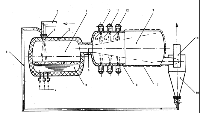
Fig. 1 ~hows a lon~itudinal cros~-~ection of a reaction
vessel with a gas coolin~ chamber connected t~ereto.
;A drum-~haped reaction ves~el 1 with new linin~ 2 ~nd a
;clear volume of 150 ~3 contains 50 to 120 t of iron melt 3
.~
', ,' ~ - . ' : . ,
so-s
.
with a carbon content of approx. 2.5~ ~nd a temperature of
1550C. Via tuyere~ 4, which are ~upplied by hot ga~ conduit
5, a hot blast with a temperature of 1200C i~ blown at a
blowin~ r~te o~ 2000 Nm~/min onto the ba~h surface. A mixture
of coke, lime and fine ore reduced to ~ustlte i~ added to the
hot bla~t directly before it enters tuyere 4. The ~ixture ha~
a temperature of 800C and reaches hot blast ~onduit 5 via
conduit 6. The feed rates of the individual componen~s of this
mixture are 1350 kg/min for the partly reduced ore, 400 kg/min
for coke and 90 kg/min for lime. Through bottom nozz~es 7 with
a clear diameter of 18 mm, 200 k~/min of gas-flame coal i3
blown into the metal bath, ~o that sufficient bath a~itation
is obtained.
In this way, approx. 1 t o~ liquid iron is produced per
minute. The waste ~a3 with a temperature of approx. 1680C i5
~onducted on the shortest path throu~h hot gas conduit 8 into
gas cooling chamber 9O In thi~ tank 9 the waste gas is cooled
down to approx. 800 to 90QC by the addition of po~dery mate-
rials, before the ga~ ~tream touche the opposit~ wall o~ the
tank.
Through feed ~onduit 10 blo~ing in apertures 13 are ~upplied
with fine ore. The fine ore flows at a ~lo~ing rate of 1600
k~min into yas coolin~ tank 9, where it i9 heated and reduced
to FeO. Dow~stream, approx. 200 ~g/min of limestone powder is
supplied throu~h blowing in apertures 14 of supply conduit 11
associated therewith. In the hot waste ~as stream deacidifica-
tio~ takes place, i.e. the supplied limestone i~ split into
CaO and C02. Finally, gas-~lame coal i8 supplied to ga~ cool-
ing chamber 9 through blo~ing in apertures 15, ~hich Co D u~i-
cate with supply conduit 12, at a rate of 520 k~/min, and
cokes in the hot waste ~as stream.
Ga~ cooling tank 9 ha~ a linin~ 16 in the area o~ the feed
apertures ~or the powdery ~ub3tance~, and adjacent thereto the
wall i~ water-cooled in the area which can be hit by the waste
~as stream.
The mixture o wa3te gas, dust and the reacted-out powdery
substances collects in hot cyclone 18, from ~here the mixture
of coke, FeO and CaO to be fed to the reaction ve~sel i5
., .
.:= 5
: ~ . .. . ~ . - . . ..
. .. . . . . . .
. .
.
.
. . .
~ . "
~f~
~ransported via ~upply conduit 6 to the feeding place. The
cleaned waste S7a~ leave~ hot cyclone 18 via condult 19 and
part of it ~erves to produce th~ hot blast. The remainder of
approx. 1900 Nm3 /min with a calorific value of 840 lccal/Nm3 ~s
available for external applications.