Language selection

Search

Patent 1286536 Summary

Third-party information liability

Some of the information on this Web page has been provided by external sources. The Government of Canada is not responsible for the accuracy, reliability or currency of the information supplied by external sources. Users wishing to rely upon this information should consult directly with the source of the information. Content provided by external sources is not subject to official languages, privacy and accessibility requirements.

Claims and Abstract availability

Any discrepancies in the text and image of the Claims and Abstract are due to differing posting times. Text of the Claims and Abstract are posted:

  • At the time the application is open to public inspection;
  • At the time of issue of the patent (grant).
(12) Patent: (11) CA 1286536
(21) Application Number: 528988
(54) English Title: PRINTING CYLINDER WITH RETRACTABLE PLATE REGISTER PIN AND METHOD OF ASSEMBLY
(54) French Title: CYLINDRE D'IMPRESSION A CHEVILLES ESCAMOTABLES D'ADAPTATION DU CLICHE, ET SON ASSEMBLAGE
Status: Deemed expired
Bibliographic Data
(52) Canadian Patent Classification (CPC):
  • 101/118
(51) International Patent Classification (IPC):
  • B41F 27/02 (2006.01)
  • B41F 27/00 (2006.01)
(72) Inventors :
  • BANIKE, RONALD (United States of America)
(73) Owners :
  • DONNELLEY (R.R.) & SONS COMPANY (United States of America)
  • BANIKE, RONALD (Not Available)
(71) Applicants :
(74) Agent: FINLAYSON & SINGLEHURST
(74) Associate agent:
(45) Issued: 1991-07-23
(22) Filed Date: 1987-02-04
Availability of licence: N/A
(25) Language of filing: English

Patent Cooperation Treaty (PCT): No

(30) Application Priority Data:
Application No. Country/Territory Date
826,978 United States of America 1986-02-07

Abstracts

English Abstract


Abstract

Printing Cylinder with Retractable Plate
Register Pin and Method of Assembly

A magnetic printing cylinder has retractable plate
register pins. The printing plate is positioned on the cyl-
inder by engagement of an edge of the plate with the pins in
extended position. The pins are moved to retracted position
and the plate wrapped around the cylinder. The pin moves
radially of the cylinder in a bushing. O-rings on the pin
limit outward movement of the pin and resist pin rotation.
In assembly of the cylinder, the pin and bushing extend
above the cylinder surface and are ground to the final cyl-
inder dimension.


Claims

Note: Claims are shown in the official language in which they were submitted.


The embodiments of the invention in which an
exclusive property or privilege is claimed are defined
as follows:
1. In a printing cylinder having a peripheral
surface and magnet structure for holding a thin elongate
printing plate thereon, two retractable plate register pins
comprising:
means defining a hole for each pin in said cylin-
der, said holes extending radially inwardly through said
peripheral surface such that the register pins being spaced
apart along a line parallel with the cylinder axis; and
a pin slidably mounted in each hole for selective
disposition in an extended position with an outer portion of
the pin extending to above the cylinder surface a distance
greater than the thickness of the printing plate for engage-
ment with said printing plate for proper alignment of the
printing plate and in a retracted position in which the pin
outer portion does not extend above the cylinder surface a
distance greater than the thickness of the printing plate,
wherein the printing plate is positioned against
the register pins for proper alignment while the magnetic
structure of the cylinder simultaneously forces the plate
down and around the cylinder surface.


2. The printing cylinder of claim 1 in which the
pins, in the retracted position, are flush with said cylinder
surface.

- 6 -


3. The printing cylinder and register pins of
claim 1 in combination with a printing plate of ferromagnetic
material having an edge surface and being registered on the
cylinder by engagement of said edge surface of the plate with
said pins in its extended position, the plate being wrapped
around the cylinder and held thereon by magnetic attraction,
the plate edge opposite said one plate edge lying closely
adjacent said one plate edge with said pins in the retracted
position.


4. The cylinder and printing plate of claim 3 in
which said one plate edge has two notches therein which com-
plements said register pins to position the plate peripheral-
ly and axially on the cylinder.


5. The cylinder and plate of claim 4 in which said
pins are cylindrical and the notches in the plate edge have
an angular extent less than 180°.


6. The printing cylinder of claim 1
in which the means defining a hole for each pin in the cylin-
der includes a bushing fitted in the cylinder with each
register pin being movable radially of the cylinder in the
bushing.

- 7 -


7. The printing cylinder of claim 6
including means providing complementary surfaces to limit
movement of the pins outwardly of the cylinder.

8. The printing cylinder of claim 7
in which said last mentioned means comprises an o-ring on
each pin which moves in an annular groove in the inner wall
of the bushing.


9. The printing cylinder of claim 6
including an o-ring on each pin to grip the inner wall of
said bushing, preventing rotation of the pins.


10. The printing cylinder of claim 6,
including:
two spaced apart peripheral grooves on each pin;
an O-ring in each groove; and
a groove on the inner wall of said bushing, receiv-
ing one of said O-rings to limit movement of the pins out-
wardly of the cylinder, the other O-ring engaging the inner
wall of said bushing to prevent rotation of the pins.


11. The printing cylinder of claim 6
in which each pin has a bore extending axially thereof, the
bore having a surface for engagement with a complementary
surface on a tool to move the pins outwardly of the cylinder
to the extended position.

- 8 -


12. The printing cylinder of claim 6
in which each pin has an axial bore therein with a relief
hole extending laterally through the pin wall.

13. The method of assembly of a retractable plate
register pin with a printing cylinder, comprising:
drilling a hole in an outer surface portion of the
cylinder;
inserting a bushing and pin in said hole, with the
pin retracted in the bushing, said bushing and pins extending
to above said outer surface portion of the cylinder;
finishing the outer surface portion of the cylin-
der; and
causing the bushing and pin to be flush with the
finished surface of the cylinder.

14. The method of claim 13 in which said pin has
an axial bore, the method including the step of filling said
bore with a removable material before cutting the bushing and
pin.

15. The method of claim 14 including the step of
thereafter removing the material from the bore of the pin.

- 9 -


16. The method of claim 13 wherein said steps of
finishing the outer surface portion and causing the bushing
and pin to be flush with the finished outer surface portion
are concurrently performed.

- 10 -

Description

Note: Descriptions are shown in the official language in which they were submitted.


36~ii3~


PRINTING CYLINDER WITH RETR1~CTABLE PI~TE
REGIS~E~ PIN P.ND ME'rHOD O~ ASSEMBLY

Specification : - :

This application relates to a plate register pin
~or positionlng a printing plate on a print:ing cylinder and
more particularly to a register pin which is movable between
extended and retracted positions and to a method o~ cylinder
assembly.
.. . .
Backround of the Invention
In 60me pr~ntlng applica~ions the printing plate ~;.
(or blanket) is mounted on a magnetic cylinder and is he~d
on the 6urface o~ the cylinder by magnetic attraction. If
precise positionlng o~ the plate on the cylinder is impor-
~ tant, the cylinder may have one or more register pins which~ ~.
- 15 locate the plate. One such construction is shown in Rosta~
. U.S. Patent No. 3,919,937~
Some printing plates are quite thin, for example,
less than .020" in thickness. The register pin should not
: extend above the plate surface. With such a small pin
height, engagement of the plate edge with the pin while ma- :
nipulating the plate o~ the magnetic cylinder surface is
difficult. Moreover, to avoid having a longitudinal gap ~;
between the plate edges, it i6 necessary that both edge~ be
notched to ~it the pin.

Summary o~ the Xnvention
In accordance with the invention, the cylinder is
proviAed with a retractable register pi~.

; ' '
~. ' .
~ .
.
'~ '

'`: ~ ;

,. . .i .
. .

6~


~ nother feat~re of the i~vention is that the hole in
the cylinder is deflned by a bushing fitted in the cylinder,
the register pin being movable radially of the cylinder in -the
bushing. An O-ring on the pin moves in a groove on the inner
wall of the bushing, limiting the movement of the pin outwardly
of the cylinder. A second O-ring on the pin grips the inner
wal.l. oE the bushing, preven-ting rotat.ion of the pin.
A further feature of the invention is the method oE
assembly of a retractable plate register pin with a printing
cylinder, comprising drilling a hole in an outer surface
portion of the cylinder, inserting a bushi~g and pin in the
hole, with the pin retracted in the bushing, the bushing and
pin extending to abo~e the outer surface portion of the
cylinder, finishing the outer surface portion of the cylinder,
and causing the bushing and pin to be flush with the finished
surface of the cylinder.
Further features and advantages of the invention will
readily be apparent from the following specification and from
the drawings, in which:
Figure 1 is a diagrammatic perspective of a cylinder
with register pins and a printing plate;
Figure 2 is an enlarged fragmentary plan of the
cylinder, register pin in extended position and one edge of a
printing plate;
Figure 3 i9 a section taken along line 3 - 3 of
Figure 2;
Figure 4 is a view similar to Figure 2 with the pin
retracted and the pl.ate wrapped around the cylinder;
Figure 5 is a section taken along line 5 - 5 of
Figure 4;


~ .

.
.

~6536


Figuxe 6 is a diagram of the pin and a pull tool
u6ed in removing the pin from the retracted to extended po-
sition; and
Yigure 7 illustrates the manufacture of the cylin-
der and register pin.

A magnetic cylinde~ for a printing plate or ~or an
o~set blanket i~ shown in Peekna Canadian application
Serial No. 522,326 filed November 6, 1986, and assigned to
the assignee of this invention. The retractable register
pin of this application is particularly suited for use in
mounting a printing plate on the Peekna p~inting plate
cylinder. The register pin may also be used in mounting the
blanket and carrier plate on the blanket cylinder, as wel~
as with plates or blankets on other magnetic cylinders.
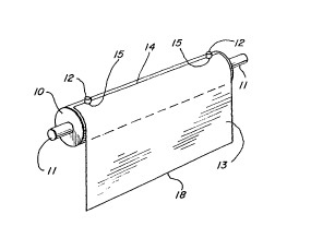
In Figure 1 a magnetic cylinder ~0 ha~ shafts 11
for mounting in a press. ~egister pins 12 extend radially
outwardly ~rom the cy~inder surface. A printing plate 13 of
ferromagnetic material has an edge 14 with notches 15 which
engage the register pins 12 locating the plate circumferen-
tially and longitudinally of the cylinder.
The register pin ~2 i6 shown in extended posit,ion
in ~igures 2 and 3, and in retracted position in ~igures 4
ana 5. With the pin 12 extended, the edge 14 of plate 13 is
positioned against the 6~de o~ the pin. The plate i6
2S wrapped around 'he cylinder 10, the pin 12 retracted as seen
in Figure~ 4 and 5 and the edge 1~ o~ the plate lies adja-
cent notched edge ~4.
With a pin diameter o~ the order o~ inch, the
notch ~5 may have a depth o~ the order o~ 1/32 inch. The
small gap in the plate surface is negligible.
The pin 12 is cylindrical and iB movable radially
of the cylinder in a bushing 20 which extends into the cyl-
inder through the magnetic structure 21, brass sleeve 22 and
into the iron core 23 of the cylinder. There are two spaced
.


;.
,

:

6~3~i

- 4 -

apart groove~ 26, 27 on the outer surface of pin 12 in which0-rings 28, 29, respectively, are received. o-ring 29 îs
seated in an elongated groove 30 in the inner wall of bush-
ing 20. 0-ring 29 engages the upper end of grooves 30 lim-
S iting the movement of pin 12 outwardly to its extended posi-
tion, as ~een in Figure 3. For a plate thickness of .015 to
.02 inch, the register pin in its extended position may be
.05 inch above the cylinder surface. Inward movement of the
register pin 1~ i~ limited by engagement of the inner end o~
the pin with the inner surface 32 of the hole in cylinder
core 23.
0-ring ~8 i8 compres6ed against the inner wall Or
bushing 20 and pre~ents rotakion of ~he register pin. The
0-rings are pre~erably on the outer surf~ce of the pi n rath-
er than on the inner surface of the bushing to facilitatemountiny and replacement. The inner end of ~he pin is ta-
pered at 33 to facilitate insertion of the pin into the
o-rings.
Register pin 12 has a longitudinal bore 34 extend-
ing therethrough to relieve fluid pressure inside bushing20. A shoulder 35 $n the bore is engageable by the head 36
of a tool 37, Figure 6, to pull the pin to its extended po-
sition. A hole 40 extends laterally through the wall of pin
12 to the longitudl~al bore 34 at a point between the
25 o-ring~ 28, 29. ~h$~ hole reliev~s fluid trapped between
the pln a~d the inne~ wall of ~ushing 2~.
~ he cylinder i~ ~abricated with the magnetic
struature 21 overslze. The ~ur~ace of the cylinder is then
ground or otherwise cut to the desired dimen~ion~ The reg-
ister pin 12 i8 assembled wikh the cylinder as a part ofthis operation. Fir~t, a hole is drilled in the cylinder to
receive bushing 200 ~he bushing, which is longer than the
desired finished dimension, i8 inserted in the hole with its
lower end seated on the surface 32 at the base of the hole
in the cylinder. Register pin 12 with the 0-rings 28, 29

is3~


mounted thereon iB then in~erted into bushing 20 with its
lower end seated on the euxface 32. The length of pin 12 is
~uch that it~ outer end i8 outside the finished surface of
the cylinder. The cylinder, bushing 20 and pin 12 are then
ground or otherwise cut to the desired fin:Lshed dimension.
The bore 34 through pin 12 is filled with a suitable materL-
al, as grease, during the cutting operation to keep metal
particles out of the bore and bush.Lng. The grease is re-
moved after the cylinder has been cut~ As indicated in F:Lg-
ure 7, the rough radius of the cylinder is of the order of3.632" while the finished radius is of the order of 3.607".
The bushing 20 and pin 12 have initial lengths which may be
such that they extend beyond the rough surface of the cylin-
der.

Representative Drawing
A single figure which represents the drawing illustrating the invention.
Administrative Status

For a clearer understanding of the status of the application/patent presented on this page, the site Disclaimer , as well as the definitions for Patent , Administrative Status , Maintenance Fee  and Payment History  should be consulted.

Administrative Status

Title Date
Forecasted Issue Date 1991-07-23
(22) Filed 1987-02-04
(45) Issued 1991-07-23
Deemed Expired 1996-01-23

Abandonment History

There is no abandonment history.

Payment History

Fee Type Anniversary Year Due Date Amount Paid Paid Date
Application Fee $0.00 1987-02-04
Registration of a document - section 124 $0.00 1987-03-30
Maintenance Fee - Patent - Old Act 2 1993-07-23 $300.00 1994-01-20
Maintenance Fee - Patent - Old Act 3 1994-07-25 $100.00 1994-06-10
Owners on Record

Note: Records showing the ownership history in alphabetical order.

Current Owners on Record
DONNELLEY (R.R.) & SONS COMPANY
BANIKE, RONALD
Past Owners on Record
None
Past Owners that do not appear in the "Owners on Record" listing will appear in other documentation within the application.
Documents

To view selected files, please enter reCAPTCHA code :


To view images, click a link in the Document Description column. To download the documents, select one or more checkboxes in the first column and then click the "Download Selected in PDF format (Zip Archive)" or the "Download Selected as Single PDF" button.

List of published and non-published patent-specific documents on the CPD .

If you have any difficulty accessing content, you can call the Client Service Centre at 1-866-997-1936 or send them an e-mail at CIPO Client Service Centre.


Document
Description 
Date
(yyyy-mm-dd) 
Number of pages   Size of Image (KB) 
Representative Drawing 2001-04-12 1 5
Drawings 1993-10-21 1 62
Claims 1993-10-21 5 142
Abstract 1993-10-21 1 26
Cover Page 1993-10-21 1 21
Description 1993-10-21 5 217
Fees 1994-01-10 1 29
Fees 1994-06-20 1 32