Note: Descriptions are shown in the official language in which they were submitted.
~ h'~
SEED DISPENSER WITH DUAL-FACED SEED PLATE
Back round and Summar of the Invention
q Y
Seed dispensers of many types are, of course,
known in the agricultural planter art, some including
horizontal seed plates turning on vertical axes and
others including vertical plates or wheels turning on
horizontal axes. The latter have many advantages over
the former but both types have certain drawbacks, among
which is the inability to discharge seeds in sufficient
volume and at reasonable speeds to conform to modern
high-speed farming operations. The present invention
is directed mainly to solutions to the problems
existing in current designs of vertical wheel
dispensers.
It is a feature of the invention to provide a
casing or housing having walls defilling a chamber that
is divided into two compartments by a circular seed
plate or wheel that rotates on a horizontal axis. One
oE the compartments receives seed, as from a hopper
carried by the planter frame, and the wheel has one or
more through openings enabling the seed to ~low through
to the other compartment. Thus the seed feeding means
supplies both compartments and the seed wheel or plate
~'`
,, , - :: . , , -
, . .. . .
. .
.
.. . . . . .
',
6~
-- 2 --
has seed-receiving cells at both radial faces for
receiving seed from the respective compartments, both
of which lead to a seed o~utlet for delivering seed to
the ground, furrow, etc. The dispenser includes means
for holding the seed level in the compartments at a
desirable height.
A further significant feature is that the seed
cells at one side of the plate are staggered angularly
with respect to those at the other slde of the plate,
thus enabling the use of a plate rim of relatively
narrow cross section. The cells at both sides are
alike to the extent of being mirror images of each
other and the shapes and dimensions of the cells are
based on the size and shape of the seeds being handled.
The plate is interchangeable with others adapted for
handling seed of other configurations. The present
design is based preferably on the practice of one seed
per cell.
The invention features also a trough or gutter
provided in the cylindrical wall or band of the casing,
the wheel or plate running midway between opposite
sides of the trough, which is wider in a cross-wise
direction at its bottom to facilitate entry of seed
into the cells but which converges to a high part of
the cylindrical wall for better cooperation with
internal means for confining the seeds to the cells
until the seeds reach a predetermined area for rapid,
positive release from the plate and into the
seed-delivery outlet, release being also assisted by
centrifugal force.
On the whole, the preferred construction is of
relatively light-weight, high-strength materials
capable of functioning over long periods of time at
substantially high speeds consistent with accurate
planting.
,
.: . . - . . -
: , ~ , .. .
.
. ... :, , :
' . ': ' ' '
s~`~
Further features and advantages of the invention
will appear as the disclosure progresses.
Description of the Drawings
Fig. 1 is a small-scale perspective of a
representative agricultural planter, wi~h a portion
broken away to reveal the exterior of the novel
dispenser and the drive therefor.
Fig. 2 i5 an enlarged perspective of the
dispenser.
Fig. 3 is an enlarged transverse section through
the dispenser.
Fig. 4 is a section as seen on the line 4-4 of
Fig. 3.
Fig. 5 is a face view of one side of the seed
plate or wheel.
Fig. 6 is an enlarged partial view of the bottom
area of the seed plate.
Fig. 7 is a fragmentary end view as seen along the
line 7-7 of Fig. 6.
Fig. 8 is a section along the line 8-8 of Fig. 6.
Fig. 9 is a section along the line 9-9 of Fig. 6.
Fig. 10 is an enlarged section of the lower part
of the casing.
Fig. ll is an enlarged section of the upper part
of the casing.
Fig. 12 i5 a perspective of the casing by itself,
with the seed plate and other parts removed in order to
show part oE the seed-confining means.
Detailed DescriPtion of a Preferred
Embodiment of the Invention
~eference will be had first to Fig. 1 for an
overview of the invention in its preferred environment.
In that Figure, the numeral 20 designates the tool bar
of a typical planter having front and rear hoppers, the
.. . .
,, ' ' ' . . ~ ' ' ' ~ ' '
,~' , . : ' ' :
65~
front one, at 22, containing seed for ultimate delivery
to a casing 24 which contains the inventive structure,
the details of which will aRpear subsequently herein.
The casing journals a horizon~al cross shaft 26
which is here shown as being chain-driven at 28 from a
transverse shaft 30 carried by the tool bar. Also as
representative of typical known planters, the present
planter includes press wheels 32 and covering wheels
34. A seed tube 36 leads from the casing 24 to between
the press wheels, again in conventional fashion. As
seen in Fig. 2, the exterior of the casing 24 is
configured to include mounting ears 38 and a depending
seed outlet 40 that i5 connected to the delivery tube
36. The ears are used for mounting the casing on the
planter frame, details not significant here.
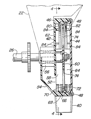
The casing is made up of first and second upright
parallel walls 42 and 44 spanned by and joined to a
band-like or cylindrical wall 46. In a preferred
design, the upright wall 42 may be formed integrally
with the cylindrical wall and the wall 44 is made
removable to provide access to the interior of the
casing, removability being shown by the cap screws 48
(Figs. 3, lO and ll) and tapped bores 50 (Fig. 12).
Fig. 3 best shows that the wall 42 has a seed inlet 52
in a lower portion thereof, forrned by a tapering wall
part 54 to which the hopper 22 delivers via the seed
tube 36. It is also seen in this Figure that a
low-friction bearing 56 spans the wall 42 and wall
portion 54 for journalling the shaft 26 which projects
into a chamber 58 formed by the casing. A circular
seed wheel or plate 60 is fixed to the chamber-received
end o~ the shaft and is disposed midway between the
walls 42 and 44, in effect providing a rotatable
partition that divides the chamber 58 into first and
second compartments 62 and 64, respectively. These
compartrnents are virtually mirror images of each other.
,
~ ~ .
' . ' ' . .
1~3~
- 5 -
The seed plate has a circular rim 66 which runs in
close relation to the interior of the cylindrical wall
46, which, in the main is~formed with or has an arcuate
concentric trough 68 centered on the median plane of
the seed plate and in which the seed plate rim travels.
The trough is, of course, open to both compartments 62
and 64 and has oppositely inwardly sloping sides to
facilitate the entry of seeds into oppositely disposed
circular series of seed cells 70 and 72 provided
respectively at opposed radial faces of the seed plate,
particularly in the plate rim. The cells 70 face and
receive seeds from the compartment and the cells 72
face and receive seeds from the compartment 64, the
seeds naturally gravitating to the lower parts o the
compartments, best seen in Figs. 4 and 10. The sloping
; sides of the trough, as said, assure that the seeds
enter the respective cells.
At this point, a significant feature of the
invention should be noted, and that is that the seed
feed means, considered broadly, enables the feed of
seeds to both compartments 62 and 64. This results
from the provisions of openings 74 ~here twol in the
seed plate. Each opening is preferably non-circular,
here shown as being oval or elliptical, each having its
longer arcs oblique to an adjacent radius of the plate,
the longer arcs being effective to agitate the seeds
and enhance the flow thereof from the compartment 62 to
the compartments 64. In practice, the seeds will
collect in substantially even volumes at both sides of
the wheel to a level generally on ~he order of the line
76 ln Fig. 4, which is at about the top of the
lowermo~t through opening 74. Because of the rotation
of the seed plate during delivery of seeds to the
outlet 40, the seed level will remain about the same,
depending upon the adequacy of the supply from the
hopper 22.
.
.
: . . .: . :
.: , ~ ., ,
.
l~r,~, ~4 3
To revert to the seed cells in the plate: These
have the size and shape of the type of seeds being
planted, an~ the dispenser is especially adapted to
seeds of substantially spherical or ellipsoidal shapes.
Consequently, the cells are of uniform size and shape
according to the criterion just mentioned and are
mirror images of each other. The cells of both
circular series open radially outwardly to the
cylindrical wall as well as opening laterally to their
respective compartments. The cell design assures
efficient seed pick-up and rapid release for delivery
to the seed outlet 40.
Looking at Fig. 12, the arrow shows that the
direction of rotation of the seed plate, or travel of
seeds carried by the plate, is clockwise. The outlet
is here shown as being disposed in the area generally
about between four and five o'clock. In Fig. 4, which
shows the opposite side of the structure, where the
seed travel is counterclockwise the outlet appears at
about between seven and eight o'clock. In order that
the seeds in the lower parts of the compartments 62 and
64 do not move directly to the outlet but must await
conveyance by the plate 60, a cross barrier 78 is
established, which is split so as to exist in both
compartments tSee Fig. 12). This barrier has a lower
end affixed to the bottom of the trough 68 at about
four o'clock (about seven o'clock in Fig. 4) and rises
to a high elevation, adjoining the cylindrical wall
generally at about eleven o'clock (Fig. 4). As the
seed plate rotates and carries seed from the lower
parts of the compartments toward the outlet 40, the
seeds are retained in their respective cells by
seed-confining means 80 and 82 respectively in the
compartments. Each confining means here takes the form
of an arcuate series of bristles 80 and 82, one series
affixed to each compartment in any suitable manner as
'
at 84 (Figs. 3 and ll). Each series of bristles
terminates just angularly past the top part of the
barrier 78 ~Fig. 4), whejreupon the cell-carried cells
are released for discharge into the outlet 40, assisted
by centrifugal force.
- It is still another feature of the invention that
the width of the trough 68 is greater at its bottom
than it is at its top, best noted by comparing the
dimensions ~-A in Fig. 10 with those at B-B in Fig. 11
The angular convergence of the trough enhances the
retention of the picked-up seeds in the seed cells
until released as explained above
The totality of features provides a seed dispenser
that enables relatively high-volume delivery of seeds
without an intolerable increase in rotational or ground
speeds. The through openings in the seed plate not
only provide for the flow of seeds from one compartment
to the other but are so designed and located as to
maintain a maximum desirable level of seeds in the
compartments. The casing and related parts may be made
of any suitable material having the characteristics of
low weight, high strength and resistance to corrosion.
Features and advantages other than those pointed out
will readily occur to those versed in the art, as will
many modifications and alterations in the preferred
embodiment disclosed, all without departure from the
spirit and scope of the invention.
, . . .. . .
.
:
. . .
.: