Note: Descriptions are shown in the official language in which they were submitted.
APPARATUS FOR RECORDING AND REPRODUCING DATA
BACKGROUND OF THE INV~NTION
Field of the Inventio_
This invention relates generally to a recording and
reproducing apparatus, and more particularly to an
apparatus of the kind which records and reproduces a
variety of data by the use of a recording medium having
a large capacity such as a magneto-optical disk.
Descri~tion of the Prior Art
Conventionally, hard disk units are known which can
write data on a large capacity disk unit for information
storage.
This unit is generally used as data storage for a
computer. The information is recorded in a concentric or
spiral track formed on the disk and the disk is rotated
at a predetermined rotational speed.
Fig. 1 is a block diagram schematically showing a
prior art recording and reproducing apparatus. Writing
data in and reproducing the same data from a hard disk
unit 1 is effected by a CPU 3 through a data bus 2. The
disk arranged in the hard disk unit is rotated at a
constant rotational speed irrespective of (not
synchronized with) the transmission rate of data
inputted on the disk. Instead, the rotational speed is
timed by the CPU 3 for recording data on the disk. The
data processed by the hard disk unit may thus be
non-sequential data.
Data communication between the hard disk unit 1 and
the CPU 3 is effected via a RAM 4 which serves as a
buffer memory. It is further possible to communicate
the data between the RAM 4 and the hard disk unit 1 at a
high speed by the use of a DMA controller, without
~.%~71~;~
interruption by the cPu 3, wherein data is processed
non-sequentially.
Data representing a still image or the like can be
processed as a one frame portion of intermittent data by
using a frame memory for the RAM 4.
Fig. 2 is a block diagram showing a construction of
a circuit for processing such burst data. Disk
controller 5 is arranged between the CPU 3 and the disk
unit 1. A required portion of burst data stored in RAM 4
is recorded in the disk unit 1 through the disk
controller 5 under the control of the CPU 3. This
construction is used, for example, in an electronic mail
system.
The "new media era" provides us with a variety of
information in many kinds of media, that is, multi-media
information. Such information includes non-sequential
or intermittent data which does not have any correlation
with adjacent data, such as computer data; data which
has a correlation with adjacent data, but is as a whole
non-sequential, such as data representing a still image;
data which has a correlation with adjacent data and is
sequential, such as digital audio data; and so on.
These data have different characteristics from each
other.
It would be useful to be able to write all the
types of data information on a disk and provide users
with the disk. The magneto-optical disk is a rewritable
large capacity storage medium and can store multi-media
information. The magneto-optical disk is different from
a hard disk unit which records and reproduces data under
strictly controlled conditions because it produces
errors at a higher ratio than the hard disk unit. Thus
the data stored in the magneto-optical disk is provided
with redundant bits for error correction codes and other
functions for detecting and correcting errors.
7i~
However, while the error correction is effective
with respect to random errors, it is not so effective
with respect to burst errors. It may be better to treat
data including errors as defective rather than
correcting the errors where computer data is concerned.
On the other hand, it is sufficient to correct errors in
data forms like PCM audio data to such a degree that the
errors cannot be audible. Errors which cannot be
corrected can be interpolated by the use of adjacent
data having a correlation with erroneous data so that
the errors will not be conspicuous.
Even so, if data is recorded in the same order as
the original data and a burst error occurs in a portion
of that data, then that data portion can no longer be
interpolated.
OBJECTS AND_SUMMARY OF THE INVENTION
Accordingly, it is the object of the present
invention to provide an apparatus which appropriately
records data having different characteristics.
According to an aspect of the present invention,
there is provided an apparatus for recording input data
on a recording medium, comprising:
a memory for storing input data to be recorded in
predetermined quantity units;
a first address control means for determining an
address of said memory;
a second address control means for determining an
address of said memory; and
an encoding means for adding at least an error
correcting code to each predetermined quantity unit of
input data, and
wherein when the input data has no correlation with
adjacent input data, the input data is sequentially
written in said memory by said first address control
7~
means, read out therefrom, encoded by said encoding
means, and recorded on the recording medium without
changing the order of the input data, and when the input
data has a correlation with adjacent input data, the
input data is written in said memory by said second
address control means, read out therefrom, scrambled,
and then the scrambled data is encoded by said encoding
means and recorded on the recording medium.
According to another aspect of the present
invention, there is provided an apparatus for
reproducing data from a recording medium, the data being
of the type in which when the data has no correlation
with adjacent data, it is encoded and recorded in the
inputted order thereof on the recording medium while
when the data has a correlation with adjacent data, it
is scrambled, encoded and recorded on the recording
medium, said apparatus comprising:
a memory for storing reproduced data in
predetermined quantity units;
a first address control means for determining an
address of said memory;
a second address control means for determining an
address of said memory; and
a decoding means for correcting possible errors in
the data for each predetermined quantity unit, wherein
when the data has no correlation with adjacent data, the
reproduced data is sequentially written in said memory
at its corresponding address by said first address
control means, read out therefrom, and outputted without
changing the order of the reproduced data, and when the
data has a correlation with adjacent data, the
reproduced data is written in said memory by said second
address control means, read out therefrom, descrambled,
and outputted.
~.2~37~
The above and other objects, features, and
advantage~ of the present invention will become apparent
from the following detailed description of the preferred
embodiment taken in conjunction with the accompanying
drawings, throughout which like reference numerals
designate like elements and parts.
BRIEF DESCRIPTION OF THE DRAWINGS
Fig. 1 is a block diagram schematically showing a
prior art data recording and reproducing system;
Fig. 2 is a block diagram schematically showing
another prior art data recording and reproducing system;
Fig. 3 is a block diagram schematically showing, by
way of example, a whole arrangement of a recording and
reproducing apparatus according to the present
invention;
Figs. 4A and 4B are diagrams showing an example of
a sector format of a magneto-optical disk;
Fig. 5 is a diagram showing a construction of the
data portion arranged in one sector; and
Fig. 6 is a diagram showing a construction of the
data portion when data is scrambled.
DESCRIPTION OF THE PREFERRED EMBODIMENT
An embodiment of an apparatus for recording and
reproducing data according to the invention will
hereinafter be described, wherein a magneto-optical disk
is used as an example of a recording medium.
on a magneto-optical disk ll, as shown in Fig. 4,
there are concentric or spiral tracks 12 formed such
that one track is traced for each rotation of the disk
11. Data is recorded on and reproduced from each track
12.
Each of the tracks 12 on the disk 11 is formed of a
plurality of sectors 0, 1, 2, ...n-l, n equally divided
~.2~166
in the direction of its circumference. On each sector,
there is recorded a predetermined amount of data and
redundant bits, such as an error correcting code and an
error detecting code, which are added to the
predetermined amount of data.
As shown in Fig. 4A, one track is formed of (n+1)
sectors, and in this example, n is determined as 31,
that is, one track is formed of 32 sectors.
A format for data recorded in one sector is
constructed, for example, as shown in Fig. 4B. To be
specific, one sector is comprised of a header portion, a
data portion, and gap portions GAP which are placed
behind each of the header and data portions.
In the header portion, there is recorded a preamble
signal at its head and following thereto there is twice
recorded the grouping of: an address synchronizing
signal ASYNC for synchronizing the address data, an
address signal ADD, comprising track address data TA and
sector address data SA, and an error correcting code ECC
for correcting possible errors in the address signal.
Further, in the data portion, there are recorded a
preamble signal at its head and following thereto, a
data synchronizing signal DSYNC and data to be recorded
on the magneto-optical disk with an error correcting
code (ECC) for correcting possible errors in the data.
The unit quantity of data to be recorded in the
data portion of each sector is generally 512 bytes,
considering that the disk is used as a storage medium
for a computer. Fig. 5 shows the construction of the
data portion for the above-mentioned case.
Referring to Fig. 5, the data recorded in each
sector is 512 bytes, i.e., Do - D511. Preceding the 512
bytes of data there are additionally recorded 12-bytes
of supplementary data comprising a track number TrNo, a
sector number SeNo, a user area and data identification
J.2~.`371~
information ID. Then, a 4-byte CRC code for detecting
errors is produced and added at the end of the preceding
524-bytes of data. The 528-bytes of data thus formed is
arranged in a matrix having 24 byte rows and 22 byte
columns, as shown in Fig. 5.
Then, a first error correcting code Cl having 4
bytes (e.g., (28, 24) Reed-Solomon code) is added to
each row of the 528-bytes of data including the 4-byte
CRC code. In the same manner, a second error correcting
code C2 having 4 bytes (e.g., (26, 22) Reed-Solomon
code) is added to each column of the 528-bytes of data.
Referring again to Fig. 5, there is recorded at the
head of each row a synchronizing signal (hereinafter
simply called "Re-SYNC") indicative of the head OL each
row, by which the data is sequentially recorded and read
along the row direction.
Reference is now made to an example of the
invention which records a variety of information on a
disk defined by the above-mentioned sector format as
well as a reproducing apparatus associated therewith.
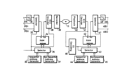
Referring now to the block diagram of Fig. 3,
reference numeral 11 designates a magneto-optical
recording disc including, e.g., a spiral-shaped track on
which the above data is recorded. A recording and
reproducing head (not shown) in the apparatus is
controlled such that the head correctly scans the
previously formed track.
Reference numeral 31Dl designates a first digital
data input terminal to which is inputted digital data
such as data from a computer, in which adjacent data
have no correlation with each other. Reference numeral
31D2 designates a second digital data input terminal to
which is inputted time sampled analog data, for example,
analog audio data sampled at various predetermined
sampling frequencies with each value being sampled as
~1.2~7~66
one word made of a predetermined number of bits, digital
data at various transmission rates of data, and so on.
Such digital data has a correlation between adjacent
data and can be interpolated with the adjacent data.
Reference numeral 31A designates an input terminal to
which are supplied analog signals, e.g., audio signals.
Digital data inputted to the terminals 31D1 and
31D2 are supplied to a selector 33 while analog signals
inputted to the terminal 3lA are first supplied to an
A/D converter 32 to be converted into corresponding
digital signals. The sampling frequency of the A/D
converter 32 can be changed to various values, e.g., 32
kHz, 44.1 kHz, 48 kHz, and so on. Further, it is
possible that the sample can be selected from various
numbers of bits, e.g., 8-bits, 12-bits, 16-bits and so
on. In the case of such digitally converted analog
signals, particularly in the case of digitally converted
audio signals, the resulting signal has a correlation
among data words so that an erroneous word can be
interpolated by words located at the vicinity of said
erroneous word. This is because the changes in
amplitude of an analog signal are not as likely to be
abrupt as in the case of a digitally generated signal.
The digital signal from the A/D converter 32 is supplied
to the selector 33.
The selector 33 selects, by manual operation or a
control signal SS supplied thereto from an external
circuit (not shown), one of the signals from the input
terminals 31Dl, 31D2 or the output of the A/D convertor
32. The digital signal selected by the selector 33 is
stored in a RAM 34. In this case, the write and read
addresses in the RAM 34 can be changed in accordance
with the input data selected by the selector 33.
To be specific, reference numeral 36 designates a
sequential address control means which generates a
~2~16~i
sequential address for the writing and reading
addresses, and reference numeral 37 designates a
scrambled address control means which generates writing
and reading addresses which follow a predetermined order
for the cases where one of the two reading and writing
of addresses is sequential and the other of the two
addresses is scrambled. One of the addresses generated
by the address control means 36 and 37 is selected by a
selector 35 to be supplied to address terminals of the
RAM 34. The selector 35 is controlled by a selection
signal SS in ganged relation with the selector 33.
When the digital data from the input terminal 31
is to be selected by the selector 33, the address
generated by the sequential address control means 36 and
selected by the selector 35 is supplied to the RAM 34 in
which each of the 512-bytes of data is sequentially
written at an address corresponding thereto, i.e., D
D1, D2, ... as shown in Fig. 5.
The RAM 34 generally comprises two chips of RAM
devices. Data is written into a vacant one of them and
read out from one into which data has been fully
written. In the read-out procedure, data is
sequentially read from the RAM 34 in the same order as
the writing by the sequential address, and supplied to
an ECC encoder 38 wherein the additional information and
redundant data C1 and C2 are added thereto as shown in
Fig. 5 to thereby form the data portion for each sector.
The data portion thus formed is supplied to a recording
process circuit 39 wherein the header portion is added
thereto, as shown in Fig. 4, adequately modulated, and
recorded on the magneto-optical disk 11 as one sector.
When the data from the A/D converter 32 or the data
from the input terminal 31D2 is to be selected by the
selector 33, the selector 35 supplies the RAM 34 with
the address generated by the scrambled address control
~a~l6~;
--10--
means 37. If it is assumed at this time that the audio
data concerned is an 8-bit 2-channel stereo, first
samples Lo, Ro of the left and right channels are
respectively written at the first and second byte
positions Do~ Dl of the 512-bytes of data shown in Fig.
5, and the next samples Ll, R1 respectively written at
the 257th and 258th byte positions D257, D258, that is,
the first and second byte positions of the latter half
of the 512-bytes of data. Then, following in the same
manner, samples of even number channels are written in
the former half of the 512 bytes of data, and samples of
odd number channels in the latter half of the 512-bytes
of data, that is, data is written in a scrambled manner.
The data thus scrambled is sequentially read out
along the row direction, i.e., Do~ Dl, D2,
following the reading address signals generated by the
control means 37. In other words, data is read out in a
scrambled state and supplied to the ECC encoder 38
wherein the additional information and redundant data C
and C2 as shown in Fig. 6 are added thereto. The data
portion thus formed is supplied to the recording process
circuit 39 wherein the header portion is added thereto,
as shown in Fig. 4, adequately modulated, and recorded
as one sector on the magneto-optical disk 11.
The selection signal SS is supplied to the ECC
encoder 38 causing an identification signal, which
indicates whether the data to be recorded is scrambled
or not, to be recorded in an ID portion of the
supplementary information portion. This identification
signal may be recorded in the header portion. Further,
the identification signal may be recorded in a track
directory allocated at the most inner or the most outer
track of the disk 11 in which information relative to
data to be recorded on the disk is recorded.
The RAM 34 is shown as distinguished from a RAM
arranged in the encoder 38 for a better understanding of
the operation of the apparatus of the invention,
however, in a practical device/ thesa RAMs are replaced
by one RAM system which can serve for the both purposes.
To be specific, the redundant data C1 and C2 are
produced for the data in the one RAM by the ECC encoder
38 and written in the RAM, and then the written data
with the redundant data is read out from the RAM and
supplied to the recording process circuit 39.
If the rotational speed of the disk 11 is
determined as 1406 1/4 rpm, the data transmission rate
is 3.072 Mbps (1.536 Mbps x 2). If data, the sampling
frequency of which is 8 kHz and the word length of which
is 8 bits, is recorded on the disk it is possible to
record 48 channels on a disk. In the case of an audio
signal having a sampling frequency of 32 kHz and a word
length of 8 bits, it is possible to record 12 channels.
It is also possible to record 4 channels of an audio
signal having a sampling frequency of 48 kHz and a word
length of 16 bits.
If the rotational speed of the disk is changed,
data having a different transmission rate can be
recorded in each sector as a 512-byte data block.
The data recorded as described above is reproduced
in the following manner.
The data reproduced from the disk 11 by the head
(not shown) is demodulated by a reproducing process
circuit 40, supplied to an ECC decoder 41 wherein
possible errors are corrected, and the 512-byte data
portion is stored in a RAM 42.
In the reproducing system, it is required to switch
the address of the RAM 42, corresponding to whether or
not the recorded data is scrambled. Reference numeral
44 designates a sequential address cont_ol means
~.2~7~L66
-12-
corresponding to the sequential address control means 36
in the recording system, and reference numeral 45
designates a descrambled address control means
corresponding to the scramble address control means 37
in the recording system.
One of the output addresses from the address
control means 44 and 45 is selected by a selector 43
according to the recorded data and supplied to the RAM
42.
The output from the ECC decoder 41 is supplied to
an identification signal decoding circuit 46 wherein it
is determined from the identification signal stored in
the ID portion of the supplementary information portion
whether or not the data is scrambled. If the recorded
data is not scrambled, the selector 43 selects the
address from the sequential address control means 44
which is then supplied to the RAM 42, whereby the data
is written in and read out from the RAM 42 in the order
of the address. The read-out data is supplied to a
selector 47.
If the recorded data is scrambled, the selector 43
selects the address from the descrambled address control
means 45 which is then supplied to the RAM 42, wherein
the scrambled data from the ECC decoder 41 is
descrambled so as to be sequentially stored in the RAM
42 in the original order. Since the data is rearranged
in the original order, the data is sequentially read
from the RAM 42 in accordance with the sequential
address. The read-out data is then supplied to the
selector 47.
The selector 47 outputs data, under control of a
selection signal generated from the identification
signal decoding circuit 46 and in accordance with the
recorded data, to one of two digital data output
terminals 49Dl, 49D2 or a D~A converter 48 whose output
~ ~716~;
-13-
signal is delivered to an output terminal 49A. The
signals output from the terminals 49Dl and 49D2
correspond to the type of data input to terminals 31
and 31D2, respectively.
As described above, when the data is scrambled and
then recorded, even if a burst error occurs during a
reproducing procedure and cannot be corrected by the ECC
decoder, assuming that all of the data in the former
half of one sector is erroneous, there are still left
the odd-numbered sampled data so that the even-numbered
sampled data therebetween can be easily interpolated by,
e.g., an average value interpolation.
If the identification signal is recorded in the
header portion or in the directory, the reproduction can
be made in the same way as described above.
Further, since the identification signal is
recorded in a predetermined portion separate from the
data, the identification signal decoding circuit ~6 may
be supplied with the signal inputted to the input side
of the ECC decoder 41.
Also in the reproducing system, the RAM 42 and a
RAM arranged in the ECC decoder 41 are generally
replaced by one RAM system. To be specific, the data
and redundant data written in the one RAM are first read
out to correct possible errors in the ECC decoder 41,
and the corrected data is written in the RAM. Then, the
corrected data written in the RAM is read out.
Further, the RAM 34 in the recording system and the
RAM 42 in the reproducing system may be commonly used.
Although in the above embodiment the
magneto-optical disk is given as an example, the present
invention is not limited thereto.
As described above, according to the present
invention, the data is recorded on the disk in
accordance with the characteristics of the data to be
71~i~
-14-
recorded, so that data having a correlation with
adjacent data can be easily interpolated.
Further, for recording data which have no
correlation with adjacent data, it is possible to
facilitate the address control in the memory and thereby
simplify the software therefor.
The above description is given on a single
preferred embodiment of the invention but it will be
apparent that many modifications and variations could be
effected by one skilled in the art without departing
from the spirit or scope of the novel concepts of the
invention so that the scope of the invention should be
determined by the appended claims only.