Language selection

Search

Patent 1287370 Summary

Third-party information liability

Some of the information on this Web page has been provided by external sources. The Government of Canada is not responsible for the accuracy, reliability or currency of the information supplied by external sources. Users wishing to rely upon this information should consult directly with the source of the information. Content provided by external sources is not subject to official languages, privacy and accessibility requirements.

Claims and Abstract availability

Any discrepancies in the text and image of the Claims and Abstract are due to differing posting times. Text of the Claims and Abstract are posted:

  • At the time the application is open to public inspection;
  • At the time of issue of the patent (grant).
(12) Patent: (11) CA 1287370
(21) Application Number: 521535
(54) English Title: APPARATUS FOR MAGNETIC TREATMENT OF FLOWING LIQUID
(54) French Title: DISPOSITIF DE TRAITEMENT MAGNETIQUE D'UN LIQUIDE EN DEBIT
Status: Deemed expired
Bibliographic Data
(52) Canadian Patent Classification (CPC):
  • 182/16
  • 317/26
(51) International Patent Classification (IPC):
  • B03C 1/02 (2006.01)
  • C02F 1/48 (2006.01)
(72) Inventors :
  • FJELDSEND, OLAF, JR. (Norway)
(73) Owners :
  • OLAF FJELDSEND A/S (Norway)
(71) Applicants :
(74) Agent: GOWLING WLG (CANADA) LLP
(74) Associate agent:
(45) Issued: 1991-08-06
(22) Filed Date: 1986-10-28
Availability of licence: N/A
(25) Language of filing: English

Patent Cooperation Treaty (PCT): No

(30) Application Priority Data:
Application No. Country/Territory Date
86.3064 Norway 1986-07-29

Abstracts

English Abstract


ABSTRACT.
Apparatus for the magnetic treatment of a flowing liquid,
comprising a housing (1) and an annular permanent magnet (4)
having radially oriented pole shoes (5, 6). Within the
cylindrical space of the magnet and coaxially thereto a ferro-
magnetic cup member (7) is provided, which is in magnetic
communication with one of the pole shoes and has slots or
apertures (8) in the walls to permit the passage of liquid.
The cup member (7) is provided with a radially extending
collar (10) which together with the other pole shoe (6) form a
magnetic field gap (11) through which the liquid shall flow.
The collar (10) is part of a cap (9) adapted to be moved
axially with respect to the cup member (7) to adjust the width
of the magnetic field gap and thus the magnetic influence on
the liquid.


Claims

Note: Claims are shown in the official language in which they were submitted.

The embodiments of the invention in which an exclusive
right or privilege is claimed are defined as follows:

1. In an apparatus for magnetic treatment of a flowing
liquid, comprising a housing through which the liquid shall
flow, and at least one annular permanent magnet having
radially extending pole shoes, the permanent magnet being
mounted in the housing in such a manner that the liquid
will flow from an inlet through the cylindrical space of
the magnet and through a magnetic field gap formed
partially with one of the magnet pole shoes, the improve-
ment comprising a substantially cylindrical cup member
disposed within the cylindrical space of the magnet and
coaxially thereto, in magnetic connection with the other
magnet pole shoe, said cup member being provided with a
radially extending collar of ferro-magnetic material, said
collar forming, together with said one pole shoe, said
magnetic field gap and means for adjusting said magnetic
field gap in which the collar is axially movable relative
to the cup member.

2. Apparatus according to claim 1 in which the collar is part
of a cap.

3. Apparatus according to claim 2, further comprising a lid
connected to said housing and overlying said cap.

-4-

Description

Note: Descriptions are shown in the official language in which they were submitted.


~1 2~3~

The present invention relates to an apparatus
for the magnetic treatment of a flowing liquid such as
water, for the purpose of preventing scale formation
caused by precipitation of matter which is dissolved in
the liquid and also of preventing the corrosive effect of
the liquid on the conduits and the service apparatus
contacted by the liquid.
Such magnetic treatment of liquids, and
apparatus to effect such treatment are previously known,
10e.g. from the Norwegian Patents Nos~ 111,291, 131,006
and 145,209, and are of particular interest for the
treatment of water of the type which is apt to cause
ca].ciferous precipitations of boiler scale type or which
is apt to cause corrosion.
15Apparatus for effecting such treatment of a
flowing liquid comprises a housing through which the
liquid flo~s and in which is located a permanent magnet
in such a manner that the liquid flows through a magnetic
field gap formed partially by one pole shoe of the
magnet. More particularly, the invention concerns such
an apparatus which comprises a housing through which the
liquid flows and at least one annular permanent magnet
having radially oriented pole shoes, the permanent magnet
being mounted in the housing in such a manner that the
liquid flows from an inlet through the inner cylindrical
space of the magnet and through a magnetic field gap
formed partiall~T by one pole shoe of the magnet. The
characteristic of the apparatus of the invention is that
it comprises a substantially cylindrical ferro-magnetic
cup member mounted in the inner cylindrical space of the
magnet and coaxially thereto, in magnetic communication
with the second pole shoe of the magnet, said cup member
being provided with slots or apertures in the walls for
passage of the liquid and with a ferro-magnetic radially
extending collar which together with said first pole
shoe form the magnetic field gap. In a further
embodiment of theinvention, the collar is made as part oE
a cap member adapted to be moved axially relative to the


.
,
,.
- ~,,.. , ~',
.' ' ~ ..
'
.' '

~ ~37370


the cup member for adjusting the width of the magnetic
field gap and thus adjusting the magnetic influence, in
agreement with the flow rate and/or the physical
characteristics of the flowing liquid.
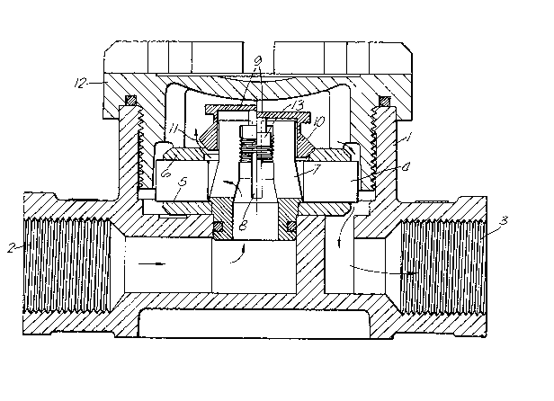
The invention shall be closer described with
reference to the accompanying drawing, showing a section
through a preferred embodiment.
The drawing shows a housing of plastics or
other non-magnetic material, in the form of a cylindrical
cup 1, the axis of which extends substantially at right
angles to the inlet 2 and the outlet 3 of the housing.
The inlet 2 extends to a central openiny in the bottom of
the cup 1, while the outlet 3 is in communication with
an eccentric opening in the bottom of the cup. Within
the cup 1 and coaxially thereto an annular permanent
magnet ~ is provided, which has radially oriented lower
and upper pole shoes 5 and 6. Within the cylindrical
space in the magnet 4 and coaxially thereto a
substantially cylindrical cup member 7 of ferro-magnetic
material is provided. This cup member 7 is in conductive
connection with the lower pole shoe 5, the lower open end
of the cup member 7 is in communication with the inlet,
and the walls and optionally even the bottom of the cup
member are slotted or apertured at 8 to permit passage of
liquid. At the upper closed end of the cup member 7 a
cap 9 is provided having a radially extending collar 10
which through the cup member 7 is in magnetic
communication with the lower pole shoe 5 and which
together with the upper pole shoe 6 form a magnetic field
gap 11 through which the liquid flows after having passed
through the slots or apertures 8 in the cup member 7.
From the said gap 11 the liquid flows on the outside of
the permanent magnet 4 to the outlet 3. The housing cup
1 is closed at the upper end by means of a lid or cap 12,
e.g. a screw cap.

~`

~3~37a3
-- 3 --

The cup member 7 and the cap 9 with the collar
lO are made in two separate parts to permit the removal
of the cap and collar unit for cleaning of the surfaces
of the magnetic field gap.
In the preferred embodiment as shown, the cap
and collar unit is adapted to be moved axially with
respect to the cup member 7 by means of a screw 13.
Thereby, the width of the magnetic field gap may be
adjusted in a simple manner at the place where the
apparatus is to be used, in agreement with local
parameters (type of liquid to be treated, liquid
hardness, liquid ~uantity) in the system iII which the
apparatus is to be mounted. In the drawing, the cap 9 is
shown to the right of the center line in a lower position
providing a narrow magnetic field gap, and to the left
o~ the center line in a higher position providing a widDr
magnetic field gap.


r~4


.. `' ' ~' , .' .

'
' .

,

Representative Drawing
A single figure which represents the drawing illustrating the invention.
Administrative Status

For a clearer understanding of the status of the application/patent presented on this page, the site Disclaimer , as well as the definitions for Patent , Administrative Status , Maintenance Fee  and Payment History  should be consulted.

Administrative Status

Title Date
Forecasted Issue Date 1991-08-06
(22) Filed 1986-10-28
(45) Issued 1991-08-06
Deemed Expired 2001-08-06

Abandonment History

There is no abandonment history.

Payment History

Fee Type Anniversary Year Due Date Amount Paid Paid Date
Application Fee $0.00 1986-10-28
Registration of a document - section 124 $0.00 1987-02-18
Maintenance Fee - Patent - Old Act 2 1993-08-06 $50.00 1993-07-23
Maintenance Fee - Patent - Old Act 3 1994-08-08 $50.00 1994-07-22
Maintenance Fee - Patent - Old Act 4 1995-08-07 $50.00 1995-07-21
Maintenance Fee - Patent - Old Act 5 1996-08-06 $75.00 1996-07-23
Maintenance Fee - Patent - Old Act 6 1997-08-06 $75.00 1997-07-23
Maintenance Fee - Patent - Old Act 7 1998-08-06 $75.00 1998-07-23
Maintenance Fee - Patent - Old Act 8 1999-08-06 $75.00 1999-07-23
Owners on Record

Note: Records showing the ownership history in alphabetical order.

Current Owners on Record
OLAF FJELDSEND A/S
Past Owners on Record
FJELDSEND, OLAF, JR.
Past Owners that do not appear in the "Owners on Record" listing will appear in other documentation within the application.
Documents

To view selected files, please enter reCAPTCHA code :


To view images, click a link in the Document Description column. To download the documents, select one or more checkboxes in the first column and then click the "Download Selected in PDF format (Zip Archive)" or the "Download Selected as Single PDF" button.

List of published and non-published patent-specific documents on the CPD .

If you have any difficulty accessing content, you can call the Client Service Centre at 1-866-997-1936 or send them an e-mail at CIPO Client Service Centre.


Document
Description 
Date
(yyyy-mm-dd) 
Number of pages   Size of Image (KB) 
Drawings 1993-10-21 1 52
Claims 1993-10-21 1 36
Abstract 1993-10-21 1 21
Cover Page 1993-10-21 1 18
Description 1993-10-21 3 134
Representative Drawing 2000-07-25 1 45
Fees 1997-07-23 1 35
Fees 1998-07-23 1 31
Fees 1999-07-23 1 27
Fees 1996-07-23 1 31
Fees 1995-07-21 1 35
Fees 1994-07-22 1 44
Fees 1993-07-23 1 44