Note: Descriptions are shown in the official language in which they were submitted.
~ ;2f~7~;~
The present invention relates to a testing
device, in particular for bottle-shaped containers, which
is constructed as a piston/cylinder aggregation, and to a
method for the testing of, in particular, bottle-shaped
containers comprising essentially plastics material.
In the course of the continuous increase in
efficiency, efforts are made to enable certain processes
to be performed in ever shorter times in order to make a
process, for example in the packaging industry, ever less
costly in time and thus economically or monetarily.
It has in this sense been shown that in the
packaglng industry the performance of individual work
operations involves not only excess space but also excess
time since the throughput time, for example in the
conserve industry, from th~ checking of the empty
containers to the checking subsequent to labelling
requires too long a proce~sing path and too long a
processing time. ~
The present invention is intended, in this
sense, to ~lmplify the present situation in the sense that
containers, especially those intended to be filled with
liquid products, and the majority of which advantageously
i ~
comprise plastics material, can be tested before they are
fil~led~ wlth ;ll~quid products in order to quickly and
~ ~unambiguously detect the rejects, for example in respect
of dimensloning~, upset strength, sealing and
thé like
:
-- 2 --
For such containers, in particular plastics
material bottles, it is known to determine the strength
thereof with the aid of an upset device. Such testing
machines, which operate with spindle drives or simple
pistons, are known~ Thereafter, the tightness, for
example, was subsequently tested in a further machine.
In this manner, not only were two different
devices or machines required but also a corresponding
amount of tlme for displacing the testpieces and for
performing the corresponding testing.
The present invention is intended to provide an
improvement in this respect in order to effect such
testing more simply ln every respect, i.e. with respect to
the space requirement, time requirement and machine
reguirement.
According to the present invention, there is
provided a testing device for bottle-shaped containers,
:
which is constructed as a piston/cylinder aggregation,
wherein`the;device comprises pistons for testing different
~properti0s of the containers at an unchanging position of
the~containers and the cylinders.
; ~ ~lso~according to the invention, there is
;~provided a~ method ;for the testing of bottle-shaped
~ containers~comprising essentially plastics material,
oompris~ing`~br~inging a container and a testing device into
a testlnq~posltioa and subsequently testing different
properties~ of the container while ~eeping the container
:~ ~
and the testing~device in the testing position.
.: ~
.. . . ~ . ,~ . .
.... .
:: .';: ,' ~ ' . :. ' .' :, .' , , , , '
i7~ 3
- 2a -
In a preferred embodiment there is provided a method
for testing the properties o~ bottle-shaped contain0rs,
characterised in that to test the.properties the container is
s subjected to a compression process while substantially
maintaining the ambient pressure in the interior thereof by
means of a pneumatically-moved, piston-like, springless
member, it being possible to adjust the gas pressure and hence
the desired compression force.
10In another preferred embodiment there is provided a
testing installation for bottle-shaped containers,
characterised in that it has at least one piston/cylinder unit
having two separate pistons which can be actively connected ;
without a spring and are individually pneumatically operable,
adjus~ing means being provided to alter the gas pressure and
hence compression force and/or leakage test pressure.
:
:
. -
:: :: :
- : :
,
7S03
An embodiment o~ the invention is described
below by way of example with reference to the accompanying
drawing, in which:-
Fig.l shows the schematic construction of a
testing installation for the testing of the up~et strength
and for the testing of the tightness of bottles
manufactured from plastics
material, and
Fig. 2 shows an axial section through a testing
device as employed in an installation according to Fig.
In Fig. l there is illustrated a testing
installation for the testing of bottle-shaped containers
of plastics material. In a testing yo~e, which can be
arranged on a rotating or linearly moving feed path, there
can be seen a testpiece 1n the form of a bottle 4
comprising a simple bottle with a neck 5~. In the upper
yoke ~arm of the testing~ yoke 3 there is fixed a testing
device 7. This~ device is constructed as a piston/cylinder
aggregat1on.~The operation of this testing device 7 is
effected by means of compresaed air, a compressed air
~connection 9 with~a pressure regulator lO being provided
~for~regula~ting the~air pressure required for determining
~ ~the~tightness of the~bottle~4. The air presaure, regulated
~ ~ in this way,~arrivés~through a~supply duct ll at a 3/2-way
~valve~;13~ which lS~ ac actuatable~that the following duct,
whi~ch~is ~provided with a manometer 14, is either supplied
: , , ,:
:,
: :':: :i " :::' '' '
50~
with ai~ or vents exhaust air from the testing device to
the atmosphere.
The installation further comprises a limit
sensor 17, which enters into opera~ion when the bottle 4,
on the neck S of which an axial pressure is exerted, does
not possess the required upset.strength and thereEore the
corresponding part of the testing device 7 descends and
thus actuates the limit sensor. The limit sensor, actuated
in thls way, ensures that during urther movement the
corresponding bottle 4 is deflected as a reject.
In a duct parallel to the supply duct there is
located a pressure regulator 20 for regulating the
adjustable tightness testing pressure to which the bottle
4 is subjected in the manner described below. A supply
duct 21 extends to a manometer 22 and to a 4/2-way valve
23. Qne of the connections of this valve 23 serves to
~attach a supply duct 25 for effecting the closure of the
bottle for the tightness~testing thereof by means of
compressed ~air, while the second supply duct 26 supplies
the compressed alr for the return of the testing device
into it's initial position.
:
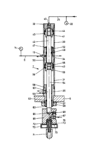
~ The testing device 7, which is shown in Fig~ 2
::
n an~enlarged~scale, includes an upper cylindrical
~ houslng 30~and a~lower cylindrical housing 31. The upper
cylin~drical housing 30 is closed by means of a cylindrical
~end~cover ~32~. The two cylindrlcal housings 30 and 31 are
screwed;together by a connecting nipple 34, The lower
` cylindrical cover 31 is closed by means of a cylindrical
::
~: :
. -: . .,, : - , : - . ~ . .
~.375!~7~
nipp~e 35. The end of this nipple 35 is provided with a
thread so that the device 7 can be secured in the upper
yoke arm 6 with the aid of a securing ring 37 and a
locking ring 38.
s The cylindrical cover 32 is provided with a
central compressed air connection boring 40 which extends
into the interior of the cylindrical housing 30, in which . . :
an upper piston 41 is slidably arranged. The piston 41 is
provided with an inner piston rod 42 having a free end
sur~ace 43. $he piston 41 is sealed relative to the
cylindrical housing 30 by a lip seal ring 44 and an O-ring
45. The piston rod 42 extends into an upper guide bushing
47, which is inserted into the connecting nipple 34 and is
provided wlth an O-ring seal 48. A compressed air passage
50 located laterally in the connecting nipple 34 is
provided with a connection nipple 51 through which
compressed air can be fed from the supply duct 11. The
connecting:nipple 34 further has a vent passage 52 which
opens i~nto the:cylindrical space of the upper cylindrical
housing~30. : ; -
.
: ~Beneath the:connecting nipple 34 there is a
lower: piston :53: provided with a piston rod 54, which
:~ ~plston:53 lS~ equipped wlth two lip seal rings 55 and 56.
Th~e cylindrical connecting nipple 35 has a
~:lateral;~compressed a~Lr passage sa with a nipple 59 which
~is~sealed~by means of an O-ring 60. The piston rod 54 is :
guided~i~n~a~ lower guide bushing:62 with an O-ring seal 63
in~the cyl~indrical;connection nipple 35. ~ :
. . :, .~ ~, , , . . , . ~, . . . .
~ ~f~7S(:~3
The lower end of the piston rod 54 is formed as
a threaded pin, which serves to retain a connection head
65, into a threaded opening 66 of which the threaded pin
is screwed. Two passages, namely a compressed air passage
67 and a connection opening 68 for a manometer, extend
radially at one side of the head 65. The two passages are
connected to one another by a longitudinal passage. This
longitudinal passage opens in turn into a lower threaded
opening in the connection head 65 and serves to receive a
connection cap 70, which in turn retains a sleeve 72 with
a longitudinal opening 73 with the help of a threaded pin
76, so that the compressed air passage 67 can supply air
through the longitudinal passage 73 o the sleeve 72 into
a central opèning of a caliber measurement head 71. An
inner seal surf~ace 75 is provided for abutment e.g. during
the performance of the tightness testing, for abutment
against the closure~edge of the bottle neck 5.
~ If the b~ot~t~le~4 is to undergo a tightness test,
then; the vaLve 23~ is adjusted so that the compressed air
arrives through the supply duct 25 ~and the compressed air~ `
connection passage 40 on;to the free front face of the
upper~piston 41 ~and displaaes the latter downwardly.
`` ~Consequently, ~the~;Eace 43 on the free end of the piston
~rod~42 pushes~agai~nst the face 43 on the free surface of
~ the~low~er~ pi~st~on ;53, sb~ that it pushes the latter,
together;~ with~ it's~piston~rod 54 and the parts attached
thereto,~ downwardly~. Consequently, the caliber measuring
head~71 arrive~s l~n the bottle neck 5 and tests the passage
~ ~37~03
therethrough. Then the sealing surface 75 of the
connection cap 70 arrives at the upper edge of the bottle
neck S. During this movement, the upper piston 41 arrives
at it's lower abutment position. In this position, the
sealing surface 75 rests with a predetermined, adjustable
pressure against the free edge of the bottle neck S, so
that the interior of the bottle is sealed relative to the
exterior. By appropriate control, the compressed air now
arrives through the passages 67 and 73 into the interior
of the bottle and the latter is filled with air~ whereby
the final pressure must be maintained for a predetermined
time so that the bottle can be passed as tight. An
appropriate control ensures the rejection of leaky
bottles. These controls, which are known, do not form the
subject matter of the present invention and are therefore
not described in detaiI.
For testing the upset resistance of the bottle
S, corresponding~ compressed air a~rrives through the supply
duct 11 and the nipple 15 and through the passage 50 into
the ~interior of the connecti~ng nipple 34, where it acts on
the free piston surface of the lower piston 53 opposite
the surface 43. By thi6 movement,; as during the tightness
testing, the seallng face 75 of the connection cap again
~;come6~to abut against the edge of the bottle neck 5. There
`25 ~ ;~is~ther~eby~exerted on~ the edge of the bottle a force,
acting in the ~direction of the longi~udinal axis of the
~bottle 4,~ which is substantially hlgher than that required ~-~
for~ sealing. In thi~s way the bottle i6 subjected to an
~:'' - ' `': ~'"',''.'.,'.'.' ',' '.. ''"' '., ,., ,' ' ': ,' '' ' ' .':',
,, .. -" ,, : , . .. , , , . : - . :
~2B7503
upset test. If the manufacture of the bottle is
satisfactory, then it withstands this upset pressure. If
the bottle is faulty, for example ~ue to a wall thickness
which is too thin or to an unevenly distributed wall
thickness or the like, then.it does not withstand the
force which is exerted on it and it buckles. Subject to
the correspondingly large stroke of the lower piston 53,
upon buckIing of the bottle 5 the closure cap 70 comes
into contact with the limit sensor and, as described,
causes the rejection operation.
For the return of the two pistons 41 and 53, the
supply duat 26 is supplied with compressed air (connection
as shown in Fig. 1) which returns the piston 53 and,
pushed in front of it, the piston rod 42 with the piston
41 back Into the upper abutment position as shown in Fig.
2. The corresponding cylindrical space is thereby vented
by the passage 50, the valve 13, as shown in Fig. 1, being
switched over so as to be switched to "exhaust".
Correspondingly, through the duct 25 air is expelled as
- 20 shown by~the valve 23. In order to prevent the formation
of a ~sub-atmospheric pressure in the upper cylindrical
space, air flows through the ventilating passage 52 from
the~atmosphere into the interior of the cylinder.
Tlghtn~ess~ testing and upset testlng can be
~25~ ~ effected in any manner freely selected in succession or
together. In order to ensure the independence of the two
tests, the stroke of the upper piston is therefore
smaller, for example by about 20mm, than that of the lower
: ~
~,.
, , , . . , . . :
'':
t7~ri03
piston 53. In that respect, it must basically be ensured
that the magnitude of the upset force, which~is to be set
as the limit force, must be higher with the interior
superatmospheric pressure within the bottle, i.e~during
the simultaneous carrying out of the tightness testing,
than that with during normal pressure prevailing within
the bottle. This circumstance can however be taken into
account by appropriate adjustment of the pressure
actuating of the pistons.
If the two test are to be effected
successively, for example firstly the upset testing and
then the tightness testing operation, then after effecting
the upset testing, the upset piston must be released,
which follows from the switching of the valve 13 as shown
in Fig. 1.
If, during the upset testing, the bottle can
withstand the upset orce, then after the expiry of the
upset testing period the piston 53 is relieved of
pressu~re, whereby if required only the pressing force
~0 appropriate for loading the upper piston 41 so
as to close the bottle 4 and causes the tightness testing
to be perEormed acts thereon.
Further functional tests can be subsequently
~ carried out, in particular other tests such as the
retentlon of the bottle for the printing thereof, a height
check for the bottle or the like. The sequential order of
: :
the~tests~or operations to be effected can be freely
selected`, it being ba~ically possible to undertake other
:: :
37~3
10-
additional operations on the bottle 4 by the provision of
other pistons.
This combined installation with the testing
device, in the sense of the mounting of the testing device
7, is in particular very suitable for high speed machines,
for example for testing carrousels, since at each testing
station the tests can be effected with a time cascade in
succession and/or together, without an additional movement
of the cylinder of the testing device and of the
containers to be tested.
With a carrousel testing machine, also referred
to as a ~testing wheel, with four or more test stations,
the construction of the machine is substantially
s;mplified with this device. It is, of course, also
;: .
possible to perform; only one of the possible tests by a
selection which ta~es place at an appropriate switching
and selection desk.
:; ~
:
:: : ~ ~ -
:: :: : : : : :
:: :
` :~ :
, .. . .
.. . . .