Note: Descriptions are shown in the official language in which they were submitted.
87~r3Z'~
AQUATIC GROWTH CUTT~R
BACKG~OUND OF THE INVENTION
-
The invention is in the field of marine drive units, and
specifically pertains to inboard/outboard drives, although it also
has application to outboard motors and sailboats.
The utilization of open, rotating propellers under water
engenders the potential problem of fouling the propeller with
seaweed such as kelp, fishing lines, and other debris that is
increasingly found in the world's oceans. In addition to the
problem of wrapping around the propeller, and thus slowing it down,
and fouling the drive unit in general, seaweed wrapped around the
breathing ports of the propeller drive housing may cut off the cool
water circulation which is relied upon by the engine manufacturers
to ma1ntain the engine within its range of operating temperatures.
If the operator does not become aware of this blocking or clogging,
the mechanism can be severely damaged or even ruined before it
becomes apparent that there is a problem.
Otherw1se, the~fou11ng can s]ow down the vessel, and cause
the operator to spend a few minutes manually unclogging the
propeller and unwinding any coiled seaweed.
Devices have~been created which are directed toward the
solution to thae problem. For e2ample, cutting blades are shown
in U.S. Patent~ no.~2,~670,728, issued on June 26, 1951, and U.S.
Patent~ no. ~2,~470,87~, issued on June lS, 1946. Although no doubt
` ~
these`devices~would be usefuI in some circumstances, they were
desl~gned~part~icu1ar1y for;ootboard motors~before the popularity
of~the~inboar;d~/~outboards,~ and they lack the versatility and
,:
-: ~-- -. . - . . . . . . . , .. : . :
a~
mounting that is required to accommodate the variet~ of both
inboard and outboard motors, as well as the older outboard. They
also do not specifically provide for means to screen out debris
which would block or clog the vent holes of the cooling .s7stem.
Additionally, there is a device that operàtes on a different
principle known as a Spurs cutter, manufactured by Spurs Marine
Manufacturing of Fort Lauderdale, Florida. The Spurs cutter
utilizes a stationary cutter with several radial blades, and a
rotary cutter which has a scissor like action against the
stationary blades to cut seaweed and fishing line, which would
wind around and foul the propeller. This apparatus, as others
mentioned above, does not address vent clogging. Also, it is
specific to the fouling rhat occurs by the winding of seaweed and
cord around the propeller, rather than the problem of fouling the
propeller drive houslng in general.
There is a need, therefore, for a marine growth cutter which
is adaptable to virtually any inboard/outboard motor, or outboard
,
motor, ànd which protects the entire, or virtually the entire
; immersed~propeller drive housing, and which specifically
addresses the problem of the ingress of debris into the cooling
:
vents of the drive~housing.
,
SUMMARY_OF_THE INVENTION
The lnstant lnvention fulf~ills the above stated needs by~
ùtilizing a pair of cutting blades, an upper blade and a lower
- bl~ade,~which are~sd~Justably ~ixed~together at a selected one of
an unllmite~d~Ya~r~iet~y~of angles. Both the upper blade and the
~lower`bl~a~de~hav;e mounts which mount on the propeller drive
.: ,. . . . .: ' ., j, ' . ' ' ' . :
Z3
housing, and both of the mounts are vertically adjustable on
their respective blades to accommodate different housings. The
mounts straddle portions of the propeller drive housing and at
least the upper mount i9 width-wise adjustable to spand the girth
of any housing, and mount to opposite sides of the cavitation
plate.
In the preferred embodiment, the upper blade mounts a pair
of screens which extend in opposite directions to spand the fresh
water inlet holes of the cooling system.
BRIEF DESCRIPTION OF THE DRAWINGS
Figure 1 is a side elevation view illustrating a propeller
drive housing in phantom to which the preferred embodiment of the
aquatic growth cutter lS mounted;
Figure la i9 a detail of the upper portion of a blade having
a straight leading edge rather than a serrated leading edge;
Figure lb lllust~rates a modlfication of the blade in which
the leadlng~edge is saw-toothed rather than being serrated or
straight; ~
Flgure 2 is~a sectloD taken along line 2-2 of Figure l;
; Figure~3~1s a section~al view taken along line 3-3 of Figure
Flgure 4~iS~a~sectlon taken a~long llne 4-4 of Figure l;
Flgurè~5~1s~a~fragma~tic side elevatlon~al view illustrating a
modiflcatlon~o~f~th~e~upper~mounting bracket of Figure l;
Fl~gure 6~is a~vlew~sl~ml1ar~to~Figure 5 illustrating another
modificatlon~of the~upp~er~mountlng bracket;
~: : :
. .. . :... . . . ......... . . ..
::
:: . . ~ . :: . : :
37~2...3
Figure 7 is a d~tail illustrating a rear cutting blade of
Figure 10;
Figures 8 and 9, respectively, are sections taken along
lines 8-8 and 9-9 of Figure 10.
DETAILED DESCRIPTION OF THE PREFERR~D EMBODIM~NT
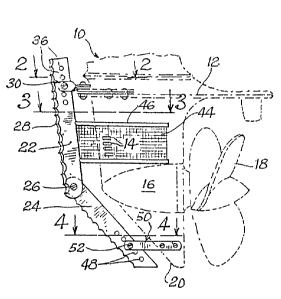
The propeller drive housing 10 extends into the water with a
generally streamlined shape, and has a horizontal cavitation
plate 12, inlet ports 14 for the cooling system, a gear box hub
16, a propeller 18, and a stabilizing fin or skeg 20.
The aquatic growth cutter of the instant invention includes
an upper blade 22 and a lower blade 24, the blades being
connected together at selectable angles, such as by ~eans of the
nut and bolt 26, which define the pivot joint between the two
.
blades through the appropriate bolt holes. The blades have a
leading edge which is serrated as indicated at 28, for better
cutting action into t~he kelp or seaweed, or whatever debris the
device`enc~ounters.~ Alternative cutting edges are shown in Figure
la, where a standard straight knife edge is illustrated, and
Figure lb, illustrating~a jagged or saw-toothed cutting edge.
Because of the~tear1ng action used by the serrated or saw-toothed
edge, ln~addit1on eo~the cu~tting action, these types of blades
would las~t longer~between~sharpenings.~;
The~upper~blade~22 is connected to the housing 10 by means
of a~mou~nting~clam~p;~30,~seen ln Figure l and even better in
Figu;:re 2~ Th~e u~pper mounting~cl~amp 30 of the preferred
embod~imè~nt~ s~a~wish~bone-t;ype clamp, having a forward portion 32
Co;mprl;sing;a~pair o~-wl-ted brackets that~twist from the
.. : . ~: : . . . . . : ................... . ~ .
- . - . . .: , . . . . .
~ ~S`~ ~,~.3
horizontal forwardly to the vertical and span the upper blade
28, to which it is bolted at 34. As indicated at 36, the upper
blade is provided with a series of vertically spaced boltholes so
that the clamp 30 is vertically adjustable on the blade.
Centrally of the clamp 30, there is a vertical pivot defined
by yet another bolt 35 which passes through the horizontal tabs
of the twisted members and through the front ends of the arms 38
of the wishbone which forms the clamp 30. The arms 38 are thus
freely adjustable in and out to accommodate the varying
thicknesses of the portion 40 of ~he housing just above the "
cavitation plate, with the forward portions of the arms being
provided with boltholes so that they can be bolted as at 42
directly to the cavitation plate.
Lower on the upper blade 22, there is mounted a U-shaped
filter element 44 which~ spans around both sides of the housing 10
at the level of the inlet ports 14 to prevent materials whîch
would otherwlse cl~og the cooling system from ever entering tnese
ports. The screen~is reinforced at its upper and lower edges by
bow-shaped members;46 so that the screen element doubles as a
support for the upper cuttlng blade.
At the~lower end of the unit, the lower blade is provided
with a series of selec~table vertical apertures 48 to which the
:
lower mounting~bracket 50 is bolted at 52. This element, as
shown from~;the top~ln~Flgure 4,~ sctually comprises two separate
; arms 54 which spsn~the;~ske;g 20 and are~bolted to it at 56.
Bec~ause~of~th~e design of the~aguatic growth cutter, it
i~s sd]us~table;~to~fit vlrtuallyisny propeller drive housing of any
. , . .. , ~ . . .
~;f 3~23
inboard/outboard, or arly outboard motor. It is adjustable not
only in the vertical points of attachment by virtue of the
selectable bolt holes 36 and 48 of the llpper and lower cutting
blades, respectively, but the upper mounting bracket 30 has the
expandable arms 38, and the lower mounting bracket 50 has
separate, expandable arms 54 to accommodate varying thicknesses
of the housing. The cutter is adjustable to accommodate skegs of
different rake by virtue of the pivotal connection 26 between the
upper and lower blades. Thus, any conceivable configuration of
housing can be matched by the invention.
A slight modification is shown in Figure 5, in which the,
mountmng clamp 30 is replaced with mounting clamp or bracket 58,
which only utilizes two twisted arms 60 to pass from the vertical
orientation of the cutting blade to the horizontal extension
necessary to~enable it to be bolted to the cavitation plate.
Although the expansion of the individual members 60 would not be
as great as the sep~aration that is possi~ble for the arms 38,
noneth~eless, a certain amount of varlation would be accommodated.
Yet another means of mounting the upper blade is shown in
~: :
~ Figure 6, in which a yoke 62, much like the lower mounting
::
bracket 50, connects the~ lower blade to the uprigh;t portion of
the housing just~above the cavitation plate 12.
Figures~ 7~hr~ough 10 relate to accommodating the cutter to a
~keel-type ss~ilboat lnd]~cated at 64. ~In this embodiment, the
rudde;r~66 woul~d~be~ protected from fouling by a blade 68 screwed
directly~in;to the~ bottom 70 of the boat. The dual-bladed cutter
of~the~ins~tant 1~nvent~lon ls s~wiveled to~match the contour along
th. ~er~lcsl ~ A_~ linc be~ween~th-~front of the keel 72 and the
~ z~37~3
front of the boat's bottom. The upyer blades 22 and 24 are
mounted to the respective surfaces of the sailboat by means of
yokes 74 and 76, respectively, which are screwed, bolted, or
otherwise attached to the boat as needed. The yokes as shown in
the drawings are connected to the blades by welding.
The utilization of the dual, pivotal blade structure
provides a versatile and efective aquatic growth cutter which
need not be manufacturer~specific, but can be provided in one, or a
small number, of models to fit virtually any kind of
inboardjoutboard drive, outboard motors, jet boats, and even with
some modification, the leading edge of the keel of a sailboat.
The invention thus being described and illustrated, I hereby
claim as fo~llows:
,
::
- : :
~ ~ ,