Note: Descriptions are shown in the official language in which they were submitted.
~ZlY7S;~9
66~39-1372
This invention relates to a dilatation catheter with angled
balloon.
In angioplasty procedures, it ha~ been found that there are
certaln vessels in the heart and in other parts of the body such
as the kidneys which are difficult to treat with conventional
straight balloon dilatation catheters. This is particularly true
where the stenosis occurs in a bend in the vessel which makes it
very difficult to treat the stenosis. There is therefore a need
for a new and improved dilatation catheter and method which can be
u~iliæed for treating stenoses of that type.
Accordingly, the invention relates to a balloon catheter
comprising a flexible, eIongate tubular memher having at least one
lumen extending therethrough and having proximal and distal
extremities, an lnflatable balloo~n carried by the distal extremity
of the tubular member and preformed to subtend a predetermined
intarior angle between about 35 and 160 when inflated, a tubular
element extendlng at least~through the balloon interior which is
preformed to subtend a predetermined interior angle between about
35 and 160 and;adapted to receive a guide wire therethrough, and
a fluld communlcatlon passageway between a lumen in the tubular
member and;~the interior~of the balloon for inflatiny and de~lating
the balloon. ~ ;
`
The method~for utllizlng the catheter comprises the steps of
~advancing ~
~"
~ .
~ Z ~7~3~
the guide wire through the catheter to straiyhten the
- angled balloon o~ the catheter, inserting the yuide wire
into a vessel of a patient, moving the catheter over the
guide wire, advancing the guide wire so that it extends
through the stenosis and advancing the angled balloon
over the guide wire into the stenosis, inflating the
angled balloon while it is positioned in the stenosis,
deflating the balloon and thereafter removing the balloon
catheter and the guide wire from the vessel.
Additional objects and features o~ the invention will
appear ~rom the following description in which the
preferred embodiments are set forth in detail in
conjunction with the accompanying drawings.
THE DRAWINGS
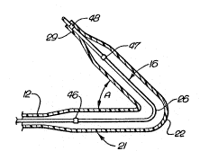
Figure 1 is~a side elevational view partially in cross
section of a dilatation catheter having angled balloon
incorporating the present invention and having an angled
protective sleeve on the angled balloon.
. ~
Figure 2 is~a cross-sectional view taken along the line
` 2-2 of~Figure 1.
`
` ~ 25 Figure 3 is an enlarged cross-sectional view of the
` distal extremity of the~catheter shown in Figure 1 but
without a guide wire extending through the same.
~Figure 4 is a~view similar to that shown in Figure 3 but
30~ with a guide~wlre extending through the balloon.
~ .
`Figure 5 is a view similar to that shown in ~igure 3 but
showing the~angled balloon straightened aut in a manner
~so that it can be inserted into the vessel of the
35~
' ~: ,: ' :' . - ~ ' ` : ' .
~;~875~9
patient.
Figure 6 is an enlarged side elevational view of the
distal extremity of another embodiment o~ a dilatation
catheter with angled balloon carryiny directional
markers.
Figure 7 is a further enlargement of one of the
directional markers shown in ~igure 6.
DETAILED DESCRIPTION OF A PREFERRED EMBODIMENT
In general, the dilatation catheter with angled balloon
consists of a flexible elongate tubular member having
first and second lumens extending therethrough and
having~ proximal and distaI extremities. An angled
balloon is carried by the distal extremity of the
tubular member. ; The elongate tubular member includes a
tubular element which extends through the balloon and
has the first lumen extending therethrough. The first
lumen is of a size that is~capabIe of receiving a guide
~wire so that a guide wire can extend through the
balloon. ~ Means is provided for establishing
~communication between the second lumen and the interior
;25 of the balloon~for inflating and deflating the balloon.
T~e~balloon has a~configuration so that when .it is
lnf1ated;it~wi11~ subtend a suitable angle ranging ~from
about~35~or less to about 160 or more.
30;~ More`particularly, ~the dilatation catheter 11 of the
present~ invention ~;consists of a flexible elongate
tubular~member 12 which carries first and second lumens
or~fLaw~passage~s 13~ and 14 which extend therethrough.
The;~lumens~or flow passages 13 and 14 can be provided in
35~ ~a~suitab~le;manner, as~Por~example, extruding the tubular
::: : : :
1287~i;39
member 12 so it is provide~ with two of such passages
extending longitudinally of the same. ~lternatively, as
shown in Figure 2, the two flow passayes 13 and 14 can
be provided with a first lumen or flo~ passaye 13 which
extends through an inner tubular member 16 and in which
the second lumen or flow passage 14 is formed by an
annular flow passage or lumen 14 extending between the
outer surface of the inner tubular member 16 and the
inner surface of an outer tubular member 17. The
tubular member 12, if formed with this co-axial
construction can be formed in the manner described in
U.S. Letters Patent 4,323,071. By way of example, the
inner tubular member 16 can be formed of suitable
plastic such as polyester or polyolefin. The outer
tubular member 17 also can be formed of a polyolefin or
a polyester.
,
By way of example, the outer tubular member 17 can have
suitable dimensions such as an inside diameter of 1.15
mm (.046 inch) with an outsids diameter varying from 1.4
- 1.43 mm ~(.056 ~to~.057 inch). In this example the
inner tubuIar member 16 can have a suitable inner
diameter such as 0.5~ mm (.020 inch) and an outer
diameter of O.~9 mm (.035 inch). However, it should be
understood~that~larger~or~smaller tubular members can be
employed, if~desired. The outer tubular member can, for
example, have an~outer diameter as large as .064 inch or
as~small as 0.5 mm (.020 inch).
30~ An angled balloon 2~1 is carried by the distal extremity
of~the~tubul~ar member 12. The angled balloon 21 can be
`~formed~ with ~a~ bend 22 so that the interior angle
subtends an angle A~ ranging from about 35 or less to
abou~160 or~more. ~ Such an angled balloon can be made
in~ several d~ ferent ~ways. By way of example, the
:~ :
:. i. . . ... . . . . ................................ .
. , . , . - ,. ., . ~: . ~ , . , -
... . .. . . ~ ~ . . . ,.
~L287539
balloon can be first formed in a mold, as ~or example, a
glass mold which has the desired con~igu~ation for the
balloon. alternatively, if it is not de~ired to utilize
a mold, the balloon can be formed in the conventional
180, or straight, configuration and then heat treating
the same, as for example, by the use of heated air or a
heated solid coming into contact with the balloon
material at an appropriate area to form the desired
angle by introducing shrinkage in that area of the
balloon. Since it is often desirable a form a balloon
which has an angle of approximately 90 with the guide
wire inserted into the same, it is desirable to form the
balloon with a lesser angle, as for example, 45 as
shown in Figure 3 to accommodate forces applied on the
balloon by the guide wire when the guide wire is
inserted into ~he first lumen and extends through the
first lumen and particularly through the portion of the
first lumen which extends through the angled balloon.
~ The angled balloon 21 is formed of a suitable polymeric
material such as a polyester which can be formed with
:
very~thin walls of great strength. This material can be
extruded and blown to form an angled~balloon. By way of
~example,~such~ a~balloon can have an outside diameter, as
for example, ranging ~from about 1.5 to about 4.0
millimeters. Such a baIloon can have a wall thickness
as thin as 0.025 mm (.OOl~inch) and still be inflated to
` pressures in~the~ range ;of 10 to 15 atmospheres. If
desired, the~ inner tubular member 16` also can be
provlded~with~a bend 26 of the same angle as the bend 22
` ~ ~3;0~provided for~the angled balloon.
The~angled ~ballcon 21, after it has been formed, can be
secured~to~the~distal extremity of the tubular member
12.~ If a separate balloon is used rather than an
:
.... ,: ~ .. - ~ . . . ; : .
:L2~7539
integral balloon, the proximal portion 28 of the balloon
can be necked down and secured to the distal extremity
of the outer tubular member 12 by suitable means such
as an adhesive or by heat if irradiated plastic is used
for the balloon. The distal extremity 29 of the balloon
is also necked down and can be secured to the distal
extremity of the inner tubular member 16 by a shrink fit
or, alternatively, by the use of an adhesive.
As can be seen from the construction shown, means is
provided in the form of the first lumen or flow passage
13 having an inside diameter of 0.5 mm (.020 inch)
extending through the tubular member 16 which is adapted
to receive a guide wire 31 of a conventional type, as
for example, the .018 "Hi-Torque Floppy" (trademark)
guide wire manufactured and sold by Advanced
Cardiovascular Systems, Inc., of Mountain View,
California. As can-be seen from the construction shown
in ~Figure 4, means is provided for establishing
communication; between the second lumen or flow passage
~14 and the interior of the angled balloon 21 so that
; the~ balloon can be inflated and deflated as hereinafter
described. ~ The distal ~extremity of the inner tubular
member 16~ can be rounded~as shown and can be relatively
~5 soft.~ The distal~ extremity can have a maximum diameter
of,~or example, ~1.13 mm (0.045~ inchj and a length of
~approximately 9 millimeters. The balloon itself can
;have~ a~ length of; 10-50 millimeters and preferably
~ ~ approximately 30 millimeters with 15 millimeters being
30 ~ provided on~each side of the bend 22.
A three-arm~ adapter ~36 is mounted on the proximal
extremity;~oP the;tubular member 12. The sidé arm 37 of
the~adaptèr 36~is adapted to receive a vent tube 38 for
-/ 35 ventIng a~ir~from~ the balloon 21 as it is inflated. The
~;287539
center arm 39 is in communication with the first lumen
or flow passaye 13 which extends complet~ly through the
dilatation catheter 11 and particularly through the
balloon ~1. Another side arm ~1 is provided which is in
communication with the second lumen or flow passaye 14
and serves as a port for introducing a li~uid medium for
inflating and deflating the angled balloon 21.
Suitable means is provided for ascertaining the position
of the balloon in the distal extremity o~ the catheter
11 when it is being used in an angioplasty procedure and
consists of radiopaque markers. For example, as shown
in Figure 1, a pair of radiopaque markers 46 and 47 can
be provided within the balloon on the tubular member 16
adjacent to the proximal and distal extremities o~ the
balloon. An additional marker 48 can be provided
adjacent the tip of the inner tubular member 16. The
radiopaque markers 46, 47 and 48 can be in a suitable
form, as for example, gold bands.
In~making the angled balloon 21, it is desirable to form
the angled balloon with an angle A which is less than
the desired angle, as for example, 45 as shown in
Figure 3. This is because when the guide wire 31 is
25~ inserted through the balloon as is shown in Figure 4,
the~guide wire will decrease the angle of the be~nd, as
for examplej by changing the angle of the balloon from
approximately 45 to approximately 85. In order to
make ~it easier to insert the angled balloon into the
30 ~ vessel, it is sometimes necessary to straighten the
balloon;~in some suitable manner. One wa~ to accomplish
; ~ this~is to make a vent tube 38 stiff enough to provide
the~ desired~degree~of straightening when it is inserted
to the distal~ extremity of the balloon. The relatively
35 ~stiff vent tube has~ a tendency to remain essentially
:: :: ~ :
: ~ : :
~7S3~1
straight and this tube and the yuide wire acting
together can straighten the balloon so it only subtends
a small angle B (see Figure 5), e.g., O to 15, with
the axis of the catheter shift. If desired, in order to
obtain sufficient straightening of the balloon, a
stiffer guide wire can be utilized until the balloon has
advanced to a location near the stenosis. The still
guide wire can be removed and a more flexible guide wire
exchanged therefor and inserted into the balloon.
In order to retain the desired bend in the balloon 21
during shipment and storage before use of the catheter
11, an angled sleeve 49 is provided which is slipped
over the balloon 21 and is frictionally retained
thereon. The sleeve has a length slightly greater than
the length of the balloon 21. The sleeve can be formed
of plastic having a wall thickness so that the sleeve is
relatively rigid. Thus, the sleeve ~9 will retain the
balloon at the desired angle during shipment and
sterilization and storage. This ensures that the
; balloon 21 will have the desired angle when the catheter
11 lS used.
'
~ Operation~and use of the dilatation catheter 11 with
angled balloon ~in performing the present method may now
~;~ be ~briefly~ described~as~ follo~7s. let it be briefly
assumed that it is desired to open a difficult stënosis -
whlch~extends around an angle in an arterial vessel of a
~patient. A catheter with an angled balloon is selected.
30~ A vent~tube 38 is positioned in the balloon so that its
distaI; extremity is near the distal extremity of the
balloon. ~ The balloon 2~1 is filled in a conventional
manner ~by introducing radiographic contrast liquid
through the~inflation port 41. As the liquid enters the
:~lnterior ~of the angled~balloon 21, the air in the
,
~: : :
:: : :
: ~: i :
. . . , : , . , , . , :., , . : . .
~ i3~
balloon will be pushed forward and will be vented to
atmosphere throuyh the vent tube 38. Thc balloon 21 is
then deflated by withdrawing the radioy~aphic contrast
li~uid therefrom and maintaining a vacuum w.ithin the
balloon. The vent tube is then withdrawn so that its
distal end is near the proximal end of the balloon
unless it is being utilized to straighten the balloon,
in which case it is positioned as desired to provide the
desired degree of straightening. Thereafter a guide
wire 31 is selected and introduced through the first
lumen 13 and through the angled balloon 21 as shown in
Figure 4 so that the balloon with the guide wire therein
assumes a conformation with the desired angle. If this
angle is approximately ~5 to 9O, assuming that is the
lS~ angle desired by the physician performing the
angioplasty procedure, frictional means may thereafter
be inserted to further straighten the balloon so that it
can be inserted into the vessel. As explained
previously, this can be accomplished by utilizing the
~` 20 vent tube or;a stiffer~ guide wire to straighten the
angled~balloon. After~the balloon has been straightened
to the angle B of O to 15 from the catheter shaft, it
;~ can be advanced into the vessel of the patient into the
region of the stenosis by first advancing the guide wire
~25 31~ in the vessel and then advancing the dilata~tion
catheter~ ~ll on the guide wire until it reachçs the
` `stenosis. After the stenosis has been reached and it is
; deslréd~ to; have the~ balloon assume an angled
confoxmation,~as for example, approximately 9O, the
30~ vent~;~tube;~3~a~ can~be withdrawn permitting the balloon to
gradually ~a~ssume~ its angled condition and to permit it
;to~be~advanced~into~and through the stenosis. After it
is~asicertained ~by observing the markers on the catheter
that the~balloon had~been~advanced sufficiently far, the
~35~bal~]oon~can~ be~ inflated by the introduction of a
i3~1
radiographic contrast liquid into the inflation port 41.
After the stenosis has been enlarged, the angled balloon
can be deflated and the dilatation catheter 11 and the
guide wire 31 removed from the vessel in a conventional
manner.
It has been found that in many cases, regardless of the
orientation of the balloon 21 and its angle, when the
balloon is inflated it will assume the conformation of
the vessel in which it is disposed so that it will
assume an angular position which corresponds to the
angular position of the stenosis. This makes it
unnecessary to rotate the distal extremity of the
catheter so that the angular balloon has the desired
angularity with the respect to the stenosis.
; If it is desired to more closely track the angular
position of~the angled balloon 21, suitable spaced apart
markers 51~and 52 can be placed within the balloon 21
20~ (see Flgure 6) to make it possible for the physician
viewing~the balloon 21 under a fluoroscope to ascertain
~its~angular position before inflation of~the same. The
markers 51 and 52~ can~be~provided on the inner tubular
member 16 within the balloon adjacent the proximal and
25~ distal~ extremities of the balloon 21. The markers 51
and~52 have a~ distinctive relationship to the angular
position of the ball~oon. The markers 51 and 52 are
~formed~of a~suitable material such as gold ribbon 53
with~ a sultable wldth such as 0.25 mm (.010 inch) and a
~30~ thickness of 0.05; mm (.002 inch), which is wrapped onto
a~;mandrel~(not~shown) to form a double helix as shown in
Figure~7~;by~the~solid and broken lines. A solder joint
can~ be~ formed~at~the overlap of the gold ribbon. The
ribbon 53~ls~trimmed~and the markers 51 and 52 are then
35~;removed from~;tbe mandrel. The first double helix band
~L2~37S39
or marker 51 is placed in an angular position on the
inner member 16. The second double helix band or marker
52 is placed on the inner tubular member rotated by 90
from the position of the first band 51. Each of these
double bands 51 and 52 can be fastened to the inner
tubular member 16 by suitable means such as an adhesive.
By observing the positions of the first and second bands
51 and 52 under fluoroscope, it is relatively easy for
the physician to ascertain the rotational position of
the angled balloon with respect to the stenosis. If the
angled balloon is improperly rotated, the angled balloon
can be rotated to the desired angular position by
rotating the main shaft of the catheter 11 provided by
the tubular member 12. By observing the relationship
between the first and second markers or bands 51 and 52,
` the physician can ascertain relatively precisely the
~position of the angled balloon~ This is particularly
~desirable prior to inflation of the angled balloon 21 in
the vessel.
~, 20
While the invention has been described with reference to
a catheter~'having~a separate vent tube for the balloon,
it~can~also be;~employed with a self venting catheter
~having a ~small channel or a plurality of small holes
25~ which p~ermit~the~pa~ssage;of air but not liquid inflation
~medium from the balloon.
It~ ;app-ront from~the foregoIng that there has been
provided~a, dilatation catheter and method utilizing an
30~ angled~balloon ~which makes it possible to treat what in
the~past, has'~been~considered to be inoperable stenoses
and~still~;to enlarge the same in a relatively simple
angiop1asty procedure. Because of the construction
provided, it 'is possible for the physician to relatively
35~precisely position~ the balloon of the dilatation
7539
catheter be~ore dilating the balloon.
~: :
:: :