Note: Descriptions are shown in the official language in which they were submitted.
lZ875~1 -
,
OPTICAL CATIIETER
Tecllnical Field
This invention relates to small diameter endoscopes
05 and more particularly to such an optical catheter havi~g
a coupling means on the proxlmate end for releasable
attachment to a console Eor viewing by the surgeon on a
video screen or monitor. In an emergency, the optical
catheter may be attached to an eyepiece.
Backqround ~rt
Prior to this invention, liyht beams have been used
both for illumination and for treatment of disease in
patients. However, all oP these instruments have had
eyepieces when utilized with visible light.
U.S. Patent No. 3,858,577 to Bass, et al. discloses
an endoscope of substantial size for performing laser
surgeryO In this device, a conventional light is used
through fibe~ optics to illuminate the operating site
and laser light is used to perform a surgical procedure.
U.S. Patent No. 4,011,403 to Epstein, et al. -
discloses a fiber optic laser endoscope. The device
utili~ès a laser beam as a light source and an optical
fiber as a light transmitter. The sensing means ~ -
includes a TV camera located at the investigated site.
The laser beam produces three different wavelengths
which produce white light. Also ultraviolet or infrared
light can be used. The camera is separate from the
fiber optics and the laser.
~ U.S. Patent No. 4,313,431 to Frank discloses an
endoscope deploying a lase~ light source with a light
conducting~fiber.~ This device is used for irradiating
bladde;r;tumors utllizing the laser light beam.
~ Many of the problems identified above have been
overcome by the invention set forth in commonly assigned
U.S. Patent No. 4,589~,404 to Barath, et al. wherein an
` ~ ; ~k :
~.' ' ,' ', ' . . ' ' . ' ' ' '' ~ .: ',', ' . ' ,,
754~
2-
optical catheter, having a mlcro-thin diameter, i5
provided having an interface connector at the proximate
end thereof for removably plugging into a receptacle in
a video monitor. Thus, the catheter can be separately
05 sterilized and can be easily replaced, should it become
damaged. However, if a power interruption should occur
: or a malfunction cause the monitor not to work properly,
the cathete~ disclosed in that patent can no longer be
used to complete the operation. This neccesitates
removal and replacement of the catheter with another one
having an integral eyepiece for viewing the body cavity.
This requires extra time and inconvenience and is not
desirable from the standpoint of the surgeon or the
patient. It also produces only a black and white image.
Another device which is currently available is an
imaging~lavage atheter sold under the trademark
VISICATH~ by Mlcrovasive of Milford, Massachusetts.
This device has an eyepiece with a separable catheter so
that the catheter can be replaced, should it become
damaged. This results in a cost savings since the
eyepieae~does not have to be replaced. Both the
eyeplece and the catheter are sterilizable. Thus, the
eyepiece is not usabIe with a console. Thus, in the use
of this device the sterility is destroyed as soon as the
physician puts the eyepiece against his face.
~ The eyepiece requires an optical light cable to
transmit light from a Iight source to the endoscope.
Each~manufacturer of optical light cables supplies them
~with d~i~ferent;si~zed fittings~at each end. This results
~ in~co~nfusion and frustra;tion~in the operatingAin trying
` ~to~find~an~op~tical ~light cable whose fittings ma~ch with
; thosè~of~the~ ght source and the eyepiece.
~Z~7S~l
--3--
Disclosure of the Inven-tion
This invention relates to a sterilizable optical
catheter for viewing and providing treatment within body
cavities by nonsurgical or micro-surgical procedures.
05 The catheter includes a coherent fiber optical bundle of
small diameter which extends from a distal end to a
point adjacent to the proximate end and has a planar
surface at the distal end7 In addition, a plurality of
light transmitting fibers are spaced around the outer
surface of the optical bundle. A tubular outer cover
extends over the fibers to hold them in place and the
outer cover extends from the distal end to a point
spaced from the proximate end. Optical lens means is
provided at the distal end of the optical bundle to
focus an image of a portion of the cavity on the distal
end of the optical bundle for transmission through the
optical bundle. A coupling means is also provided for
removably connecting the catheter to a viewing means in
fixed angular relationship. In a preferred embodiment
the coupling means includes an integral strain relief ;
unit which is connectable to a console unit and aligns
the image bundle and light fibers therewith. It is
formed as one piece with the catheter. In a secondary
embodiment, the coupling means is attached to the ~ -
proximate end of the catheter and has a ~iameter no
larger than the diameter of the outer cover so that the
catheter can pass completely through a trochar lumen.
~ More particularly, the optical catheter has
-~ alignment means~to angularly allgn the optical bundle
~: :
with the viewing means in the form of a longitudinal
groove extending along the coupling means for alignment
with a longitudinal rib ln the viewing means. The
viewlng means can include a removable eyepiece having a
socket~for slidably receiving the coupling means in
~ ~ .
~ ~ :
: :.
. . . . . , : . .
'. .' .- . .',".' ' ,~ ., ', ' .' ,; , :
. - . : ~ , . . - . . . : ,
. - . , . ~ . , . :
~2i 37S~l
--4--
aligned relatlonship for viewing and alternatively can
include a console contalning optics and a viewing screen
having a socket for slidably receiving the coupling
means when not on the eyepiece, for viewing the body
05 cavity on the viewing screen. Conveniently, the console
can also include a rotatable member having a plurality
of sockets spaced therearound, each socket being of
different diameter for accommodating catheters
constructed in accordance with this invention which also
have different diameters, wherein the rotatable member
is selectively alignable with the optics of the console.
From the foregoing it can be seen that a novel
method of using a sterilized cathetex for viewing and/or
treatment within body cavitles is provided which
includes inserting the distal end of the catheter into a
body cavity, attaching a first removable optic means to
the coupling means to view the body cavity,
disconnecting the first removable optic means from the
coupling means, and attaching a second removable optic
means to the coupling means to view the body cavity.
In addition, since the optical means is removable,
the catheter can be inserted through the lumen of a
larger endoscope or a trochar which has been introduced
into a body cavity, the optic means being attached to
the coupling means for viewing. After viewing, the
optic means can be disconnected and the endoscope or the ~ `
trochar can~be removed over the coupling means of the
ca~theter and the optic means reattached for further
viewing, as required.
~So that the optical catheter can be used
interchangeably either with a console or an eyepiece, a
strain relief unit is provided which has a smaller end
with a socket for slidably receiving the coupling means
in allgned relationship and has a second larger end with
:
~2b~75'~
--5--
a male connector for reception in optical alignment in a
receptacle of a viewing means. This viewing means can
be either a console or an eyepiece. The strain relief
unit can further include a bundle of optlcal fibers
05 extending longitudinally therethrough to each end wlth
are alignable with light fibers in the catheter.
Alignment pins are provided adjacent the male connector
to align the bundle of optical fibers in the unit with
the viewing means. The body portion of the strain
relief unit has a greater diameter than the male
connector and forms a planar radial facs at the junction
between the body and the connector, the light
transmitting fibers being spaced around the optic fibers
and each light transmitting fiber terminating at a
polished end at spaced points around the face for
alignmant with similar light fibers in the viewing
means. ".
The distal end of the catheter may take a number oE
forms for different usages. For example, if it is used
as an artllroscope a rigid metal jacket may be required
around the ends so that it can be introduced through an
opening formed in the joint to be examined. In some
applications it might be deslrable to have the rigid
sleeve made of maleable material, such as sterling
silver so that the device can be bent to fit the needs
of the su~rgeon in viewing a particulàr part o~ a joint.
Also, if the device is used as-a hysteroscope a maleable
sheath will allow the surgeon to mold it to fit the
uterine cavity of each patient. It could also be
attached by means of a protective metal tube to a pair
of forceps for extracting fish bones or other lodged or
foreign objects from the larynx, by way of example.
In addition,; if a special light source, special
optical~f~ilters;and special light conducting fibers are
:
7~
--6--
built into the optical catheter, it can be used for the
detection and treatment oE abnormal cells, such as
cancer cells. In this regard the patlent is given a
drug which has a particular afflnity to the abnormal
05 cells and which will fluoresce when exposed to light of
a predetermined first frequency. This light frequency
can be transmitted through special light fibers of the
optical cath~eter onto the tissue being examined. When
florescence is viewed on the moni-tor or with the
eyepiece, the surgeon will know that this is a site of
abnormal cells. Light of a second freque~ncy which will -
kill the cells can be directed down the light fibers or
through a separate and additional light fiber. If still
~ a third light channel is provided, to permit the use of
; 15 other light freguencies, various yuantitative
measurements can be done through the revised catheter.
In some situations, strobed~light may be used.
Additional advantages of this invention wlll become
apparent, when taken in conjunction with the
accompanying drawings.
Brief Description of the Drawinqs~
Figure 1 is~a perspective view o~ one form of an
optical catheter constructed in accordance with this
invention~showing specific~details o~ the coupling means
and the eyepiece; ~ ~
Figuxe Z is a~fragmentary-side elevation of one
configuration~of an eyepiece~showing the interconnection ~;
of~the~catheter~and the optics within the eyepiece;
~ Figure~3 is~a~perspectlve view showing the use of
the~optical~catheter of this invention with a trochar
~which is~ inserted lnto a~body~cavity and is used with a
console;~
Figure 4 is~an en}arged cross section of ths distal
S4~L
--7--
end of the optical catheter constructed in accordance
with this invention.
Figure 5 is a perspective view of the optical
catheter of this invention used with a maleable sheath
05 in a multilumen trochar;
Figure 6 is an enlarged cross section, taken along
line 6-6 of Figure 5, showing the end of the optical
catheter o~ this invention, when used in a multilumen .
trochar;
Figure 7 is a front elevation of a console and
video monitor connected to an optical catheter of this
invention;
Figure a is a diagrammatical plan vlew of the
interior construction of the console of Figure 7;
Figure 9 is an enlarged longitudinal section
through the socket of the monitor and the strain relief
unit of the catheter showing the interconnection between
the two;
Figure 10 is a similar section through an eyepiece
showing the interconnection:between the eyepiece and the
strain relief portion of the catheter;
Figure 11 is a vertical section, taken along 11-11
of Figure 10 showing the spring detent for holding the
strain relief unit in position; ~: .
Figure 12 is a perspective view of a preferred form
of the-opti:cal caheter of this invention with a general
purpose rigid examining tip on the distal end; . .
~ Figure 13 is an:enlarged longitudinal section,
: taken~along 1~3-1:3 of~Figure 12, showing details of the
30 : end~construction;
: ~Figure 14 is a perspective view of the optical
catheter :of this lnvention,~which is similar ~o Figure :
: 12,~but shows:a stainless steel sheath on the distal end
which may be either rigid or maleable;
,~
: ::
':
.
: . .'.: . . ' . ~ '
7~
-8~
Figure 15 is a perspec~ive view of the optical
catheter of this invention, similar to ~1gures 12 and
14 ! but showing an optical probe at the distal end of
the catheter; and
05 Figure 16 is a perspective view of the optlcal
cathèter of this invention, similar to that shown in
Figures 1~, 14 and 15, but showing the distal end in a
protective t,ube attached to grasping jaws o~ a pair of
forceps.
~est Mode for Carryinq Out the Invention
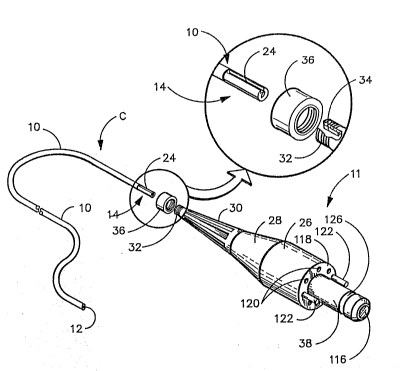
In accordance with this invention, one form of a
sterilizable small diameter optical catheter C is pro-
vided as shown in Figure 1. This cathéter includes a
cable assembly 10 which is provided at its distal end
with a lens 12 and at its proximate end with a coupling
means 14. Turning to Figure 4, an enlarged cross sec-
tion of cable assembly 10 is shown. At the center of the
cable is a coherent fiber optical bundle 16, a tubular
inner cover 18 extends~around coherent optical bundle 16
at each end and may be formed of a heat shrinkable -
Teflon or PVC material which extends along the coherent
optical bundle from the dlstal end to the proximate end.
Placed around inner covering 18 are a plurality of light
carrying bundles~20 which are made up of individual
fibers which do;not have to be coherent~ These bundles
a~e for transmitting light from~a suitable light source
to~the bod7 cavity. Alternatively, bundle 20 may be
replaced~w~th a single flexible glass fiber. An outer
cover 22~extends~around~the spaced light bundles 20, as
shown and may also be constructed o~ a heat shrinkable
~; Teflon material which~extends from the distal end of
~catheter 10~ to a~;position adjacent coupling means 14.
The couplLng meana 14 is located at the proximate
.
~ . ~ . ,. ~ , . . , :
~7~
g
end of outer cover 22 and includes a longitudlnal yroove
24 for alignment wi~h a mating rib in a viewing means or
in a straln relief unit for connection to a viewing
means. It can be made of any suitable material, such as
05 anodized aluminum or a machinable grade of plastic, such
as Bakelite~
A strain relief unit U also is illustrated in
Figure 1 which can be used to connect the catheter C
either to a console or to an eyepiece~ as will be more
fully explained below. The strain relief unit U has a
cylindrical body 26 having a first tapered section 28
and a second smaller taper section 30, as shown. The
second tapered section 30 terminates at lts distal end
in a socket 32 having a longitudinal rib 34 alignable
lS with groove 24 and held in place by locking nut 36. The
other end of strain relie~ unit U has a male connector
38 which is receivable in a console or an emergency use
eyepiece, as will be desGribed more fully below. By
having the strain relief unit removable from catheter C,
it is possible to withdraw a trochar through which the
catheter~may extend, also as explained below.
In addition, the catheter~can be connected to a
eyepiece is shown in Figure 2 which has a coupling means
identical to ~hat of strain relief unit U so that it can
be coupled to catheter~C.; It has a socket 32' with a
longitudlnal rib 34' that~is~ allgnable with the groove
24 o~ coupling means 14. Thus, the~ coupling means can
be~slid~into the socket as best seen in Figure 2 and
~ held in posi~tion;by threaded locking nut 36. The
~ proximat~e-~end o~coupling~means 14 and the ~ibers are
~flat;and~pollshed~so a~s to come into contiguous face-to-
~face~;conta~ct with a rod lens 40 for transmitting the
llght ~rom~the coherent fiber bundle to the user's eye
wh$ch~ls held~ against~the ocular face 42. The alignment
* Trade~Mark ~
. . .
lZ875~
- 1 0 -
of groove 3Z' with rib 34' assures that the image being
transmitted by the coherent optical bundle 16 is in
proper orientation with respect to lens 40 of eyepiece
E. Light ~ibers`44 surround lens 40 and extend to a
05 fixture 46 to which a suitable light source can be
attached for illuminating the body cavity by
transmitting light along fiber's 44 and light bundles 20.
Becau~e coupling means 14 has a diameter no larger
than that of outer cover 22, it can be used in a more
versatile manner than heretofore possible. Figure 3
discloses a trochar 50 which is illustrated as being
inserted through the wall 52 of a body member and into a
body cavity 54. The trochar has a first lumen 56
through which the catheter C extends into the body
cavity 54. A second lumen 58 is provided for any one of
a number oE purposes, such as for irrigation or
treatment wlthin the body cavity 54. As is well known,
. .
tro~hars of this type may have more than two lumens,
depending on their intended use.
After the procedure is completed through lumen 58,
it may be desirable to remove trochar 50 while leaving '
catheter C in place for further viewing. With the
present lnvention this is possible uslng either the
eyepiece of Figure 2;or the video console of Figure 3.
If an eyepiece E is used, as shown in Figure 2 is ~ '~
used,~ it can be removed by removing locking nut 36 and
sliding the coupling means 14 of the catheter out of
socket 32'.~ Since the c;oupling means 14 is no bigger in
'~ diamete`r than outer cover 22, the trochar can be slid to
~ the~right, as viewed in Figure 3, while leaving catheter ~'
C~in~place.~'~After removal oE trochar 50, the eyepiece E
ca~n~bé reconne~cted to the coupllng means 14, as
previously~de'scribed. The surgeon can then resume his
viewing~;of~the body cavity, as required.
., ~
~Z875~1
- 1 1 -
Conveniehtly~ the sterilizable catheter of this
invention can also be used with a video console V, of
the type shown in Figure 3. This console includes a
video screen 60. The coupling means 14 of catheter C is
05 receivable in a socket 62 which is connected to a camera
64 by suitable optics 66 which includes a continuous
focus zoom lens for transmitting the image to camera 64.
A light sou~ce ~not shown) is provided and is connected
to optics 66 by light cable 70. It is contemplated that
the invention might be utilized with catheters of
different diameters for dlfferent purposes. Thus,
socket 62 can be provided in a disc 7Z which is mounted
for rotation on the video console V about an axis 74 and
is provided with a plurality of other sockets, such as
sockets 76, 78 and 80, as shown. The socket
corresponding to the size of the catheter can be rotated
to be in the position of socket 62, so as to be properly
a}igned with the optics 64.
An important advantage of this invention is that
when a cable assembly 10 of the catheter becomes damaged
and no longer usable, it can replaced with another one
without having to replace a corresponding eyepiece.
Furthermore, the catheter of this invention can be made
to be moisture impervious~so that it can be easily
sterilized for reuse. When used with a console, the
sterility of the operating environment can be maintained
since the~surgeon d~oes not need to pu~ an eyepiece
aga~inst his~ face.~Furthermore, when the device is used
with the video monitor V, should there be a power
interruption or should the video camera or monitor
,
malfunction, it is merely necessary to slip the coupling
means 14~of the catheter out of its socket, such as
~` socket 62,~and attach a sterilized eyepiece E, which
ould be~provlded ~to the surgeon~ so that he can
:. . ~ : , :
,: ~
1;Z8~5~1
-12-
continue with the operation or procedure with min~mal
interruption.
In an alternative embodiment, shown in Figure 5,
catheter C extends through a maleable sheath 82 which
05 extends through a body canal 84 and is conformed to the
shape of the canal. In addition to catheter C, the
sheath 82 may include a laser fiber 86 for phototherapy
or photoco~gulation treatment wlthln the body cavity
into which the sheath and catheter extend.
Additionally, it may include a passageway 88 for
irrigation or suction.
A video console V' is shown in Figure 7 which is
specifically constructed for use with the strain relief
unit U which couples catheter C to the console. In this
embodiment, a video monitor 90 is provided as a separate
unit and is connected to the console by a signal
transmitting cable 92. The console V' has a front panel ;~
94 which contains the controls for the monitor camera,
llght source and filters, as well as a receptacle 96 for
receiving strain relief unit U. As best seen in Figure
8, the receptacle 96 is connected by means of a light
cable 98 to a light source 100. The receptacle 96 also
is connected to an optical assembly 102 which transmits
the image from the cable to camera 104 or transmission
by cable 92 to the monitor 90. The camera is connected
to a camera power supply 106 and the lamp assembly is
powered through Iight source pQWer supply 108. A
suitable power ~ransformer 110 and ans 112 and 114 are
provided.
~ Returning now to Figure 1, the male connector 38
carr~ies an~optical bundle 116 through the center thereof
~which aligns with the optical bundle 16 in catheter C at
socket 32~and is~polished at both ends so that light
will be transmitted from one bundle to the next. A flat
: : '
~ZB75~1
-13-
face 11~ radiates outwardly from connector 3~ to the
peripheral surface of cylindrical body 26. The ends of
light transmitting fibers 120 are spaced around this
face and also have polished ends, the opposite ends
05 t:hereof ~eing aligned with the ends of light bundles 20
of catheter C. Alignment pins 122 are provided on
opposite side of connector 38 to align the light bundles
and optical~ bundles Wit]l the corresponding light
transmitting fibers within video console V'.
Turning to Figure 9, it can be seen that within
receptacle 96 are spaced light bundles 124 which align
witl1 light bundles 120. These light bundles are fed
through light cable 98 to light source lamp assembly
100 Thus, it can be seen that the light will be
transmitted via all these light bundles from the light
source lamp source assembly to the end of catheter C for
illuminating the area to be viewed. The image will be
transmitl:ed through the optical bundles, as described to
the optical assembly 102 and camera 104~ Conveniently,
connector 38 has a peripheral recess 126 for receiving a
spring detent 128 in the receptacle 96 to releasably
hold the strain relief unit U in place in socket 129.
~ An eyepiece E' as shown ln Figures 10 and 11 which
is connectable to strain relief unit U as shown. The
eyepiece includes a socket or receptacle 130 in which
the male connector 38 extends. The light bundle thereof
is aligned with lens 132 whereby the image is projected
- through glass windaw 134 onto the eye of the surgeon.
The eyepiece E' is aIso provided with a light fixture
136 through which a burldle of light transmitting fibers
138 extend and terminate in peripherally spaced
positions around the face of the eyepiece for alignment
` with the light bundles 120 of strain relief unit U. ~s
best seen in Figure 11, a spring detent 140 extends into
...
:. -- ~ ` , -: ' .. ; : ~ ' ' , ' ' . , ' , '
.. . ~ , ., : . , j
3754~
~14-
the peripheral groove 126 of male connector 38 to
releasably hold the strain relief unit and eyepiece E'
together.
~n alternative, but preferred, optical catheter C'
05 having an integral strain relie~ unit U' is shown in
Figùres 12-6. The length of this device is
approximately 75 to 80 inches in length and is very
flexible. the tapered section ls cable of accepting
optical catheters of different diameters in the distal
end. Each optical catheter in the respective Figures
has a different tip. A general purpose tip 142 is shown
in Figure 12. This tip may be the same diameter as the
optical catheter or enlarged, as shown. This tip may
include a stainless steel jacket 144, as best seen in
Figure 13, or it may not have a metal covering at all
and be very flexible. As can be seen from this figure,
within~the jacket 144 is~optical bundle 16 having a
cover 18 and being surrounded by spaced light bundles
20. Co~nveniently, a lens 146 is provided at the end of
optlcàl bundle 16 for focusing an image of the site
being investigated on to the end of light bundle 16 for
transmission to the viewing means.
In Figure 14 a long stralght probe 148 is
illustrated which may be~a stainless steel jacket made
of ~304 tempered stainless steel. AIso, #316, ~316L and
INCONEL~ 600 steel may be used. This device may be used
~ for~insertion into various body passageways which are
- ~relatively~;straight. Alternatively, a maleable jacket
50~(~shown~;in dotted linesj may be used which can be
` ~conformed;~to~the~passageway through which it is to
extend.~Sucl1~usage~of this device might be as an
; arthroscope~and the maleable material may be sterling
-silv~er.~With this device the surgeon can bend it to fit
his~needs to~see a particular part of the joint in which
~:
lZ~5~
-15-
it is used. A~ter the procedure is completed, it can be
straightened ~or use in the next succeeding case. In
small joints, such as a finger joint, the device mlght
be approximately 1.0 mm in diameter. If it is intended
05 for use in examining an ankle joint it might be 2.0 mm
in diameter. And still laryer joints like a knee, it
might be 3~5 mm to 5.0 mm in diameter, or possible
larger. The metal sleeve can be approximately 6" to 8" --
in length. In the maleable device, a maleable form of
stainless steel might be used instead of sterling
silver. A closely wound steel spring of appropriate
length may be provided to slip over the maleable section
to aid the surgeon to shape this section to desired
configuration without crimping. This steel spring is
then removed after shaping and set aside.
If the~device is used as a hysteroscope it might be
made less than 1.0 mm in diameter. This slze is
selected to allow passage of the device into the
cervical canal without dilating the cervix. If made
this small, the optical catheter of this invention can
,
be passed into the cervix along with such other devices
such as a special fiber optic, possible of 200 to 400
microns~diameter for transmitting laser energy for
photocoagulation as previously discussed with respect to
Figure S. Also a channel for either suction or
irrigation can be;provided. With the maleable sheath,
-the device can be preformed to the shape o~ the
particular uterine cavity in which it is being used.
~ In~the embodiment of Figure 15 an optical probe 152
is;~ ustrated which has a rlgid body portlon 154 with a
hand~grlp 156~and a curved rigid probe 158 which allows
~the physlcian directional stability so that he can point
; the~device wherever he wants it to look around other
~body~portions.;~ ~
`, :
~ ,
.
, ~ - . . ,
,, . . . ~ ' . . A ' ' ' ' . ' ,
~875~
-16-
A still ~urther embodiment is shown in Figure 16
wherein the catheter C' extends lnto a proteatlve
stalnless steel housing 160 which is attached ~o the
side of a pair of forceps 162, such as a laryngeal
05 grasping device which might be used to extract a fish
bone~ from the larynx. The metal tube is welded or
otherwlse attached to lower jaw 164 of the instrument.
The upper jaw 166 can be moved relative to jaw 164 by
sgueezing handles 168 and 170 respectively. Thus, when
the physician inserts the grasping device into the
throat patient he can look around and determine where
the lodged object is.
It will be understood that other uses will become
apparent to one skilled in the art in addition to those
illustrated.
With slight modification, the optical catheter of
this invention and the console can be used as a -
fluorescence detector and provide a~means for not only
detecting abnormal cells but also for treating the cells
` 20 by phototherapy and measuring the effectiveness of that
treatment.
One~drug that has been found to be ideal for
detecting abnormal cells, such as cancer cells is a
hematoporphyrin derivative (HPD). When exposed to a -~
light frequency between 400 nm and 410 nm it will
fluoresce to a salmon pink color having a wave length of
630 nm. If the tumor containing the drug is then
exposed~to an external~laser ~requency 630 nm the cancer
cell is destroyed with no harm to surrounding normal
~cells.~ ~This~ is referred to HPD phototherapy. The
cancer~cells are~destroyed because the 630 nm light
causes a change in the oxygen in the cell to a form
:
called "singlet oxygen" this substance is toxic to the
cell.~The~;oxygen content of the cell can be monitored
, ~
::: ~ ::
~, :
lZ~375~
-17-
by utilizing laser ligh~ to measuxe absorption spectra
and by a spectrophotometer. Turnlng to Figure 8, it
will be apparent that the lamp and light source lamp
assembly 100 can be changed, such as to a halogen light
05 which provides a frequency in the visible range or
al~ernatively a band pass filter 172 can be inserted
which allows transmission of only those light rays which
fall within the desired frequency. The fluorescing
cells will then transmit light through the optical
assembly to camera 104. Again, a second band pass
filter 174 can be inserted between the optical assembly
and the camera which allows transmission only of the
reflective~fluorescent light in the range of 630 nm.
Also, various electronic equipment, known in the art for
image processing and image enhancement to increase the
brilliance of~such an image can be utilized to make the
fluorescing cells clearly visible to the physician on
the video monitor 90. Furthermore, band pass filter 172
can be replaced by other filters, and can provide for
allowing a different light frequency then in the range
of 630~nm~to be transmitted. These two frequencies of
410 nm and 630 nm can be strobed so that they are
alternately s~ent along the light fibers for fluorescence
and for killing the cells, respectively.
Although a particular photochemical material and
light~range has been described, it will be understood
that other~ photochemical materials may give o~f other
light frequencies which could be anywhere from the
infrared frequenay through the visible frequency to the
~ ~ ultraviolet frequency. In addition to a halogen light
so~urce,~a~mercury vapor light source or a Xenon light
source~could~be used with the band pass filters.
~ In addition,; the catheter can be changed to provide
fibers which are particularly effective for transmitting
:
., .. , . . ~ , ~ : . .;: : :
. ~.. , . . . .: : . . . , . . i, :, . . .
~Z~S ~l
- 1 8 -
light in the 400 nm to 410 nm frequency range. Such
fibers are available through Gallileo Electro-Optics
Company of Sturbridye, Massachusetts and other
manufacturers. Another fluorescence detector compound
05 which has been found efective ls Rhodamlne-123
` From the foregoing, the advantages of this
invention are readily apparent. An optical catheter has
been provide,d which has great versatility in that it may
be used with either a substantially standard eyepiece or
with a video camera and monitor. The catheters can be
provided in different sizes when used with a video
monitor, which may contain a plurality of sockets for
alignment with the optical means of the video camera for
connection with a catheter of the selected size.
Furthermore, the catheter can be used within the lumen
of a trochar or operating channel of a larger endoscope ~
and since the eyepiece is removable the trochar or ~-
larger endoscope can be removed without removing the
catheter and then the eyepiece can be replaced for
further viewing~ The catheter can easily be replaced
should It become damaged, without replacement of the
expensive viewing means. Also, the sterility of the
catheter can be maintained when used with the console,
which permits its use with a lower risk o~ infection.
Furthermore, no separate light cable is needed
The device can also be used for detection and
treatment~of cancer cells or other abnormal cells by
using it to excite a fluorescent dye in the abnormal -
cell by excitation wlth a selected laser light. The
fluorescence will give off its own light which can be
detected and displayed on the video monitor wh~reupon a
laser light of the same frequency can be transmitted
back~to the cell and used to convert the oxygen in the
cell to singlet oxygen thereby destroying the cell. The
:: :
-
:
:
5~L
- 1 g -
effect of the phototherapy can be monitored by
photometrlc means.
This invention has been described in detail with
reference to particular embodiments thereof, but it will
05 be understood that various other modifications can be .
effècted within the spirit and scope of this invention.
.
. . ',
"
,:
:
:
: ~ :
:
~ .
. ~
`~
:
-:.. ,- . - . ::, ~ ~ ,., .. : . .. ., , . ". ,, . . .. , . : , - :,
. .: .~ ., , : , I , - . - ;, . . . ~ ,
, - . ::: , : ~ -